
Influence of Tool Geometry and Process Parameters on Torque, Temperature, and Quality of Friction Stir Welds in Dissimilar Al Alloys

 ,
,  ,
,  , and
, and
Abstract
:1. Introduction
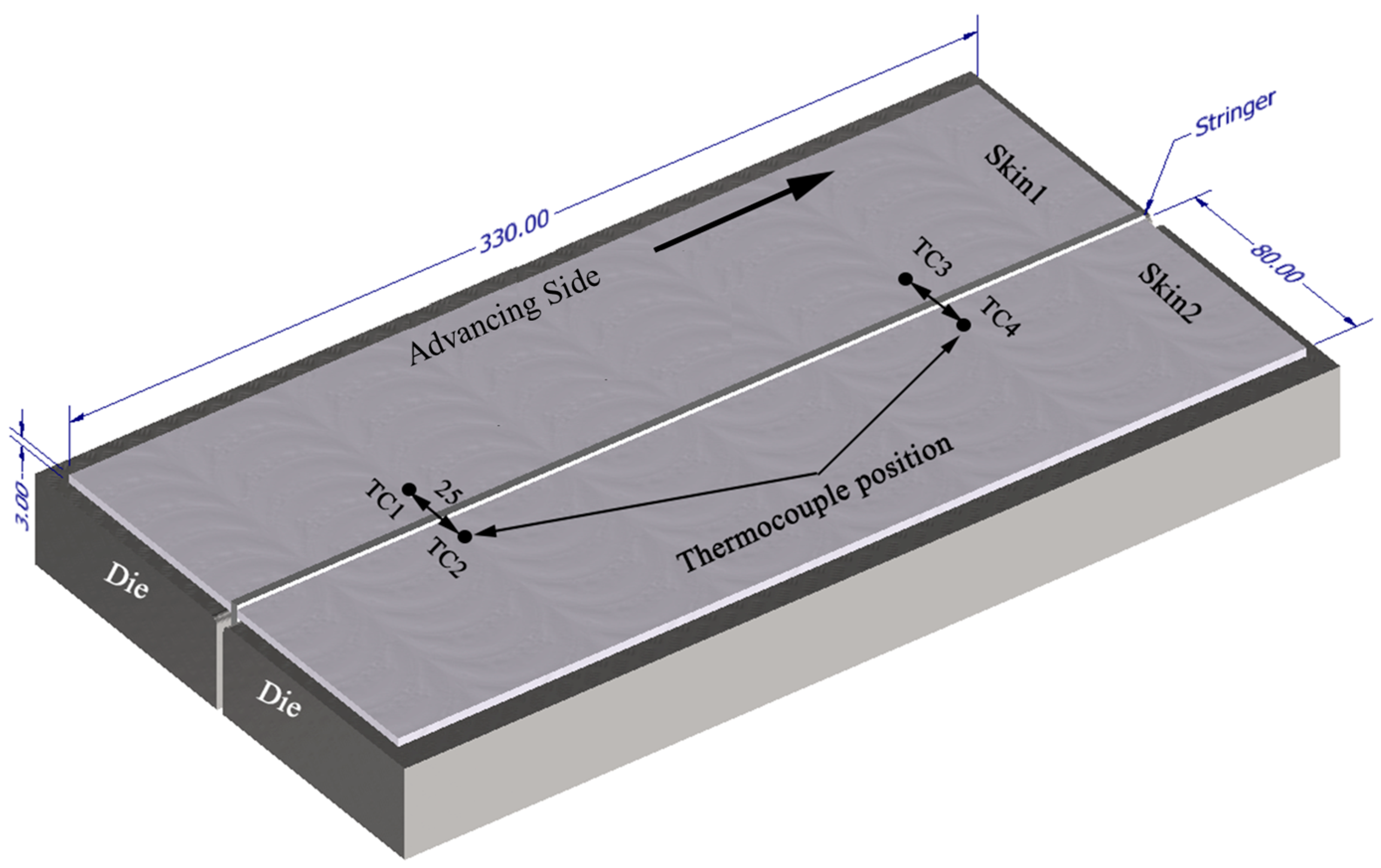
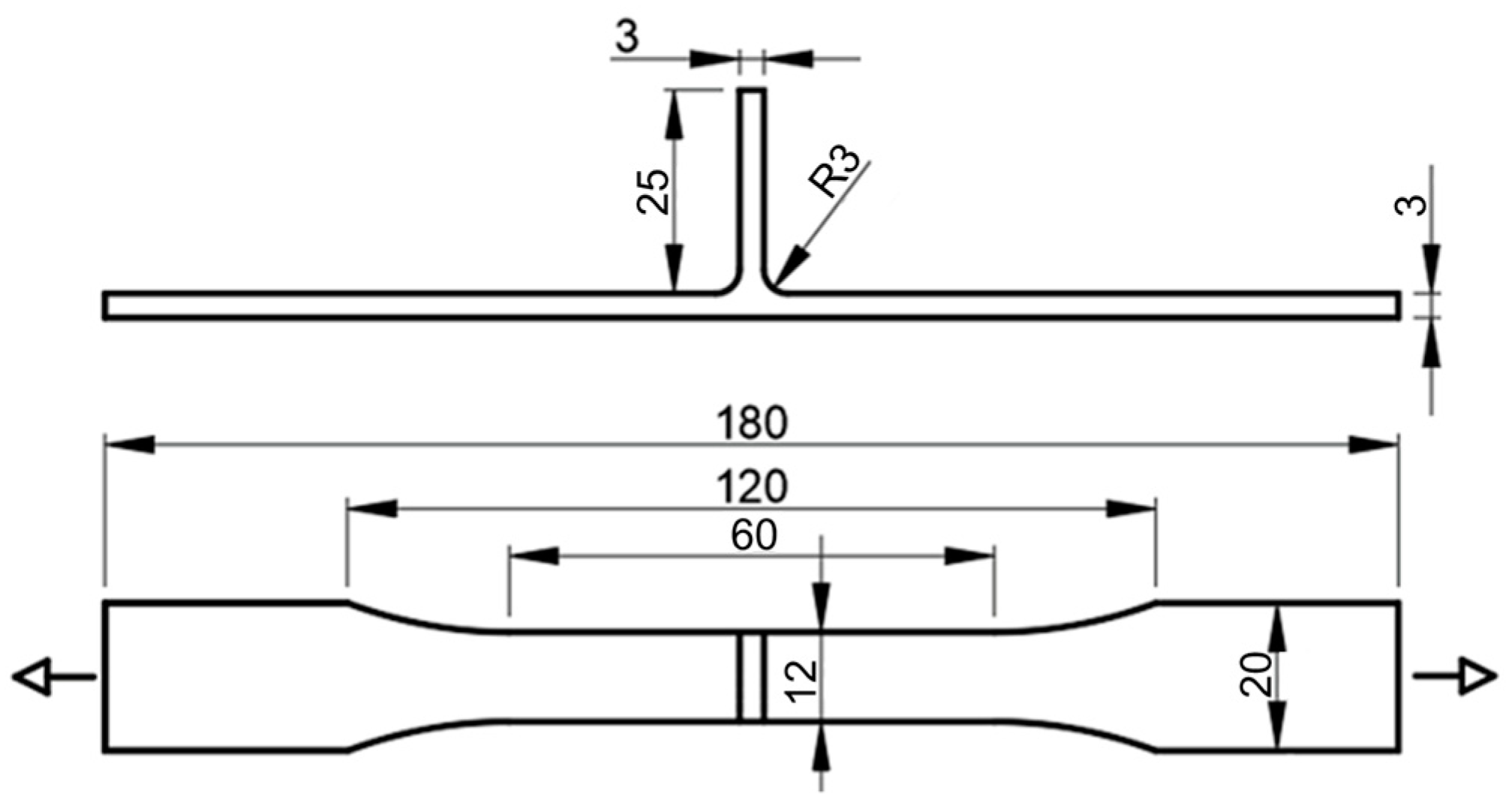
2. Materials and Methods
3. Results and Discussion
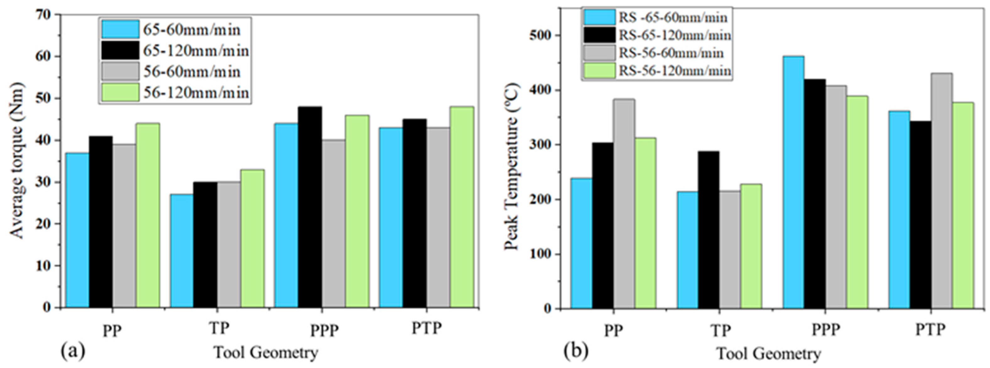
3.1. Welding Torque and Temperature
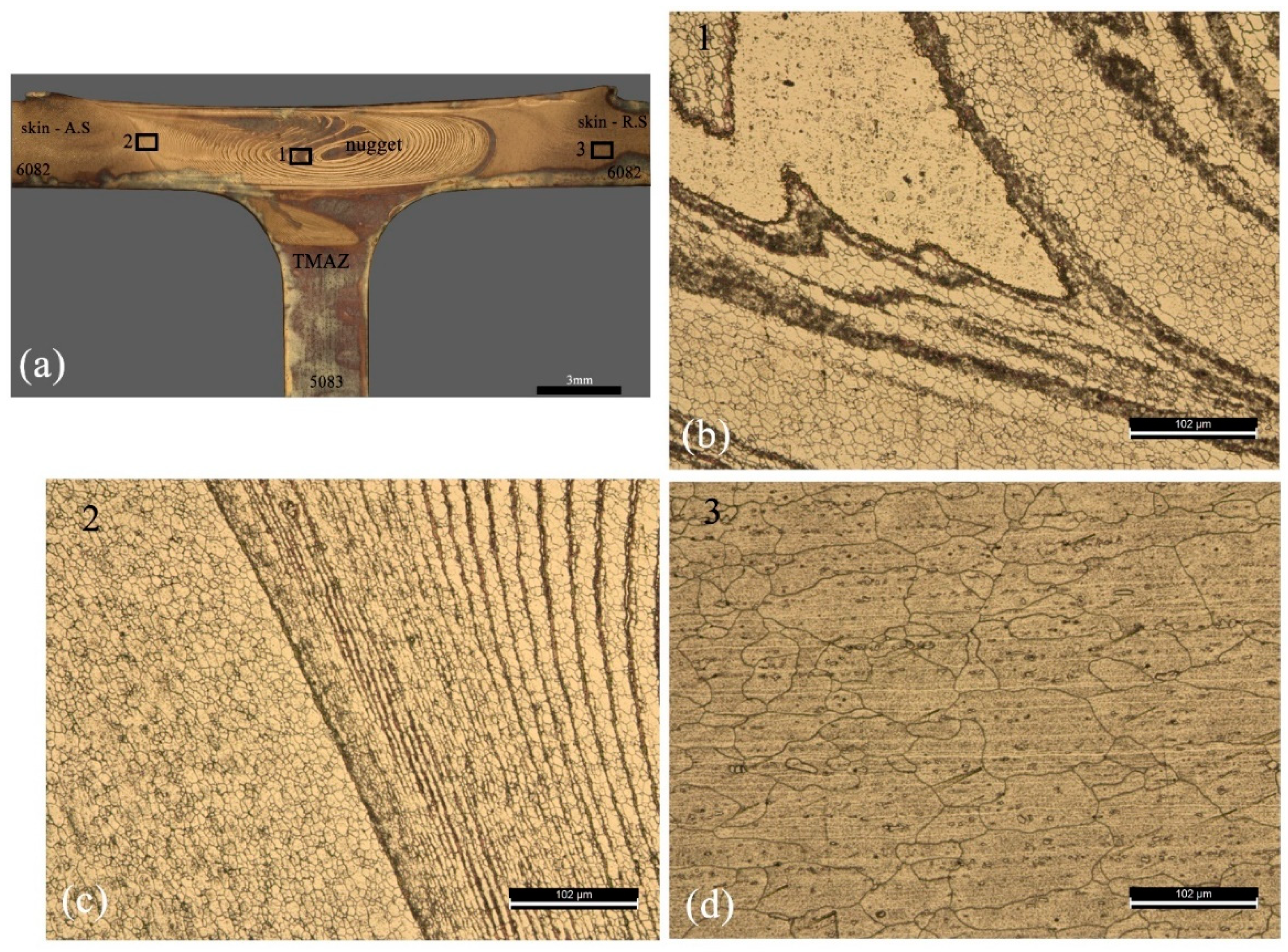
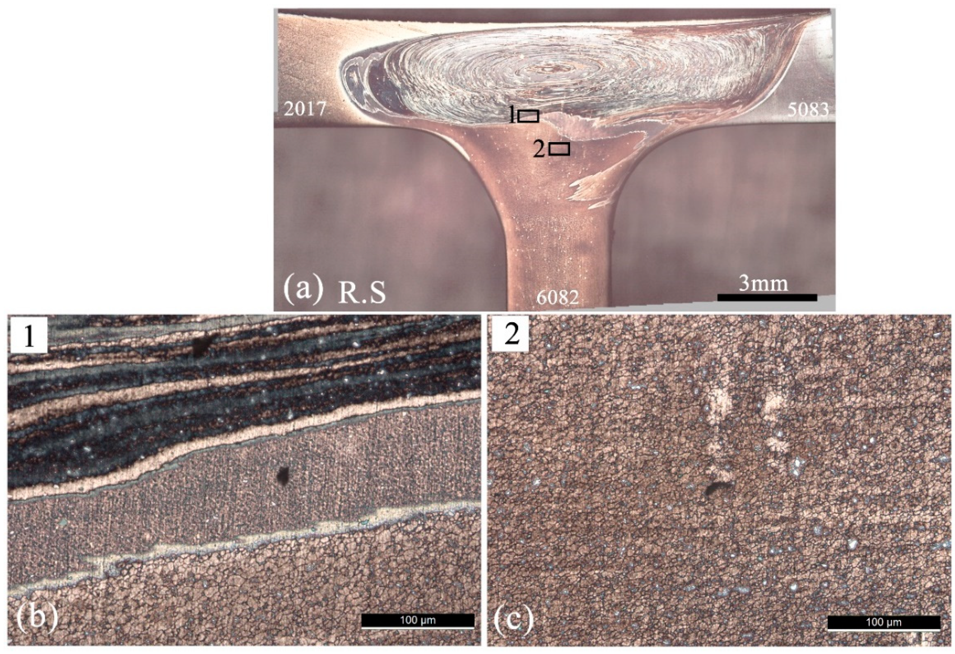
3.2. Weld Morphology
3.2.1. Dissimilar Welds
3.2.2. Tri-Dissimilar Welds
3.3. Microstuctures in the Stir Zone
3.4. Weld Mechanical Behaviour
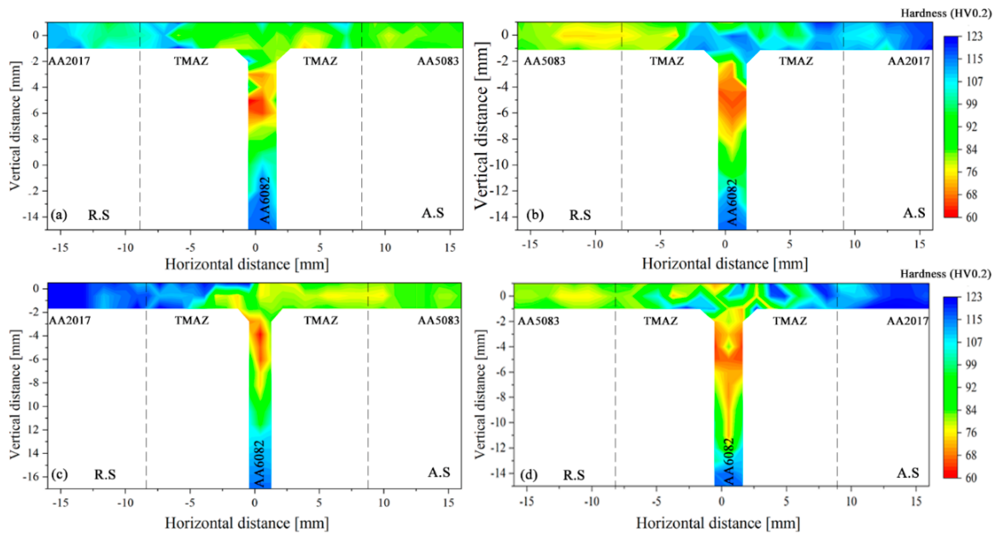
3.4.1. Microhardness
3.4.2. Ultimate Tensile Test
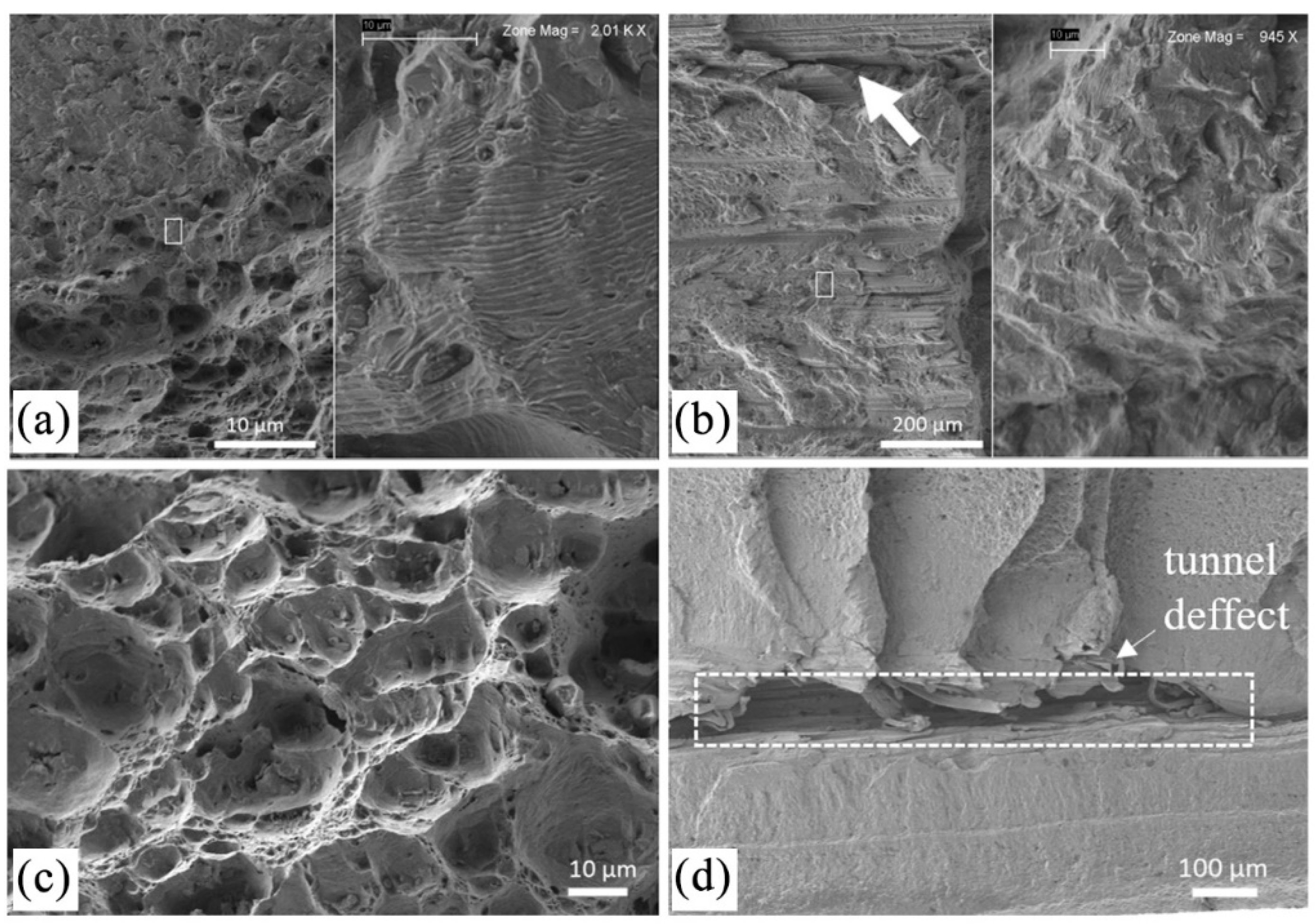
3.4.3. Fatigue Tests
4. Conclusions
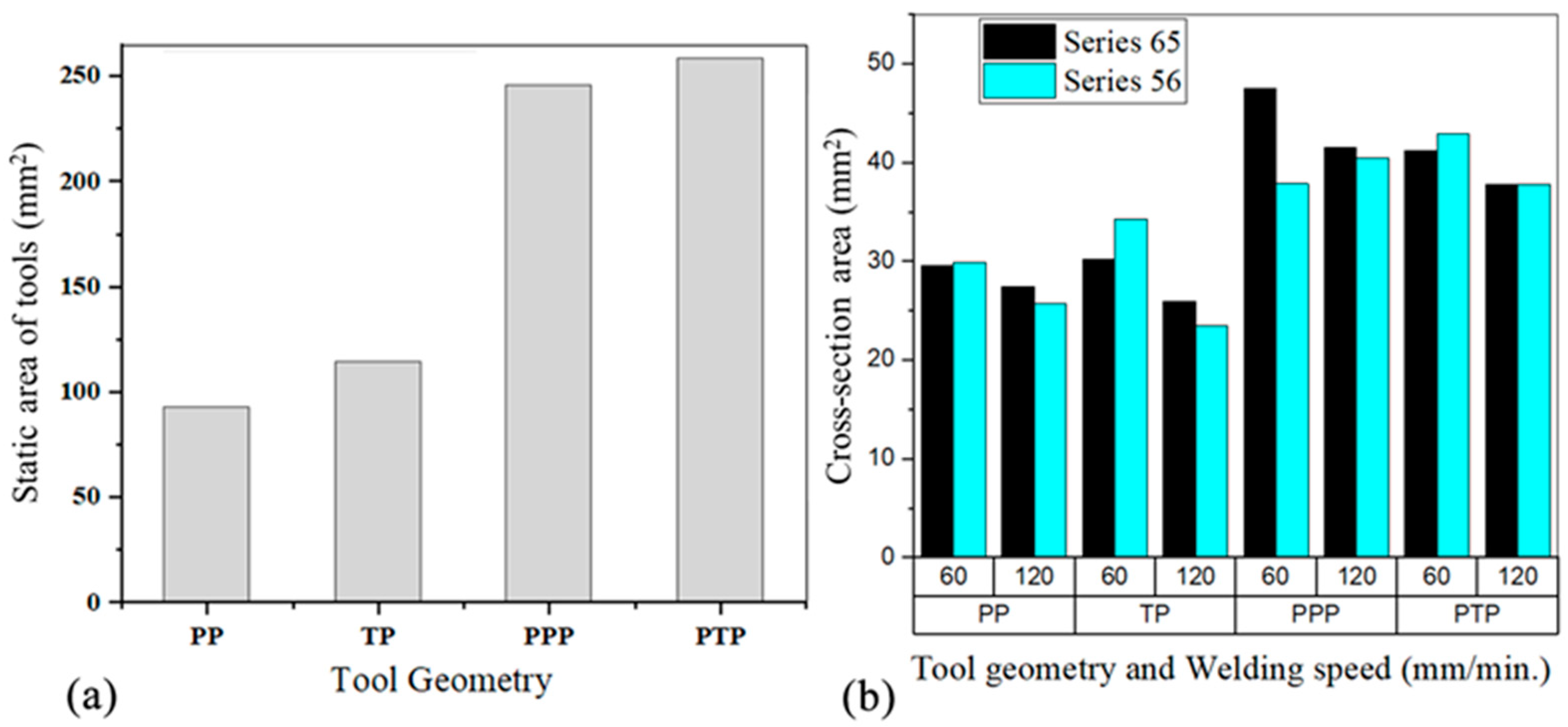
- Tools with a single pin, whether pyramidal or tapered threaded, generate lower peak temperature and torque than tools with a progressive pin. This is caused by the smaller friction area and smaller volume of material moved by the single pin tools;
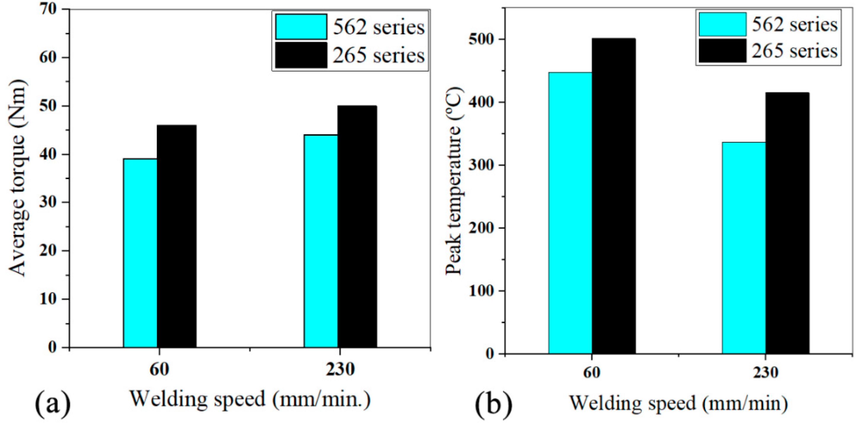
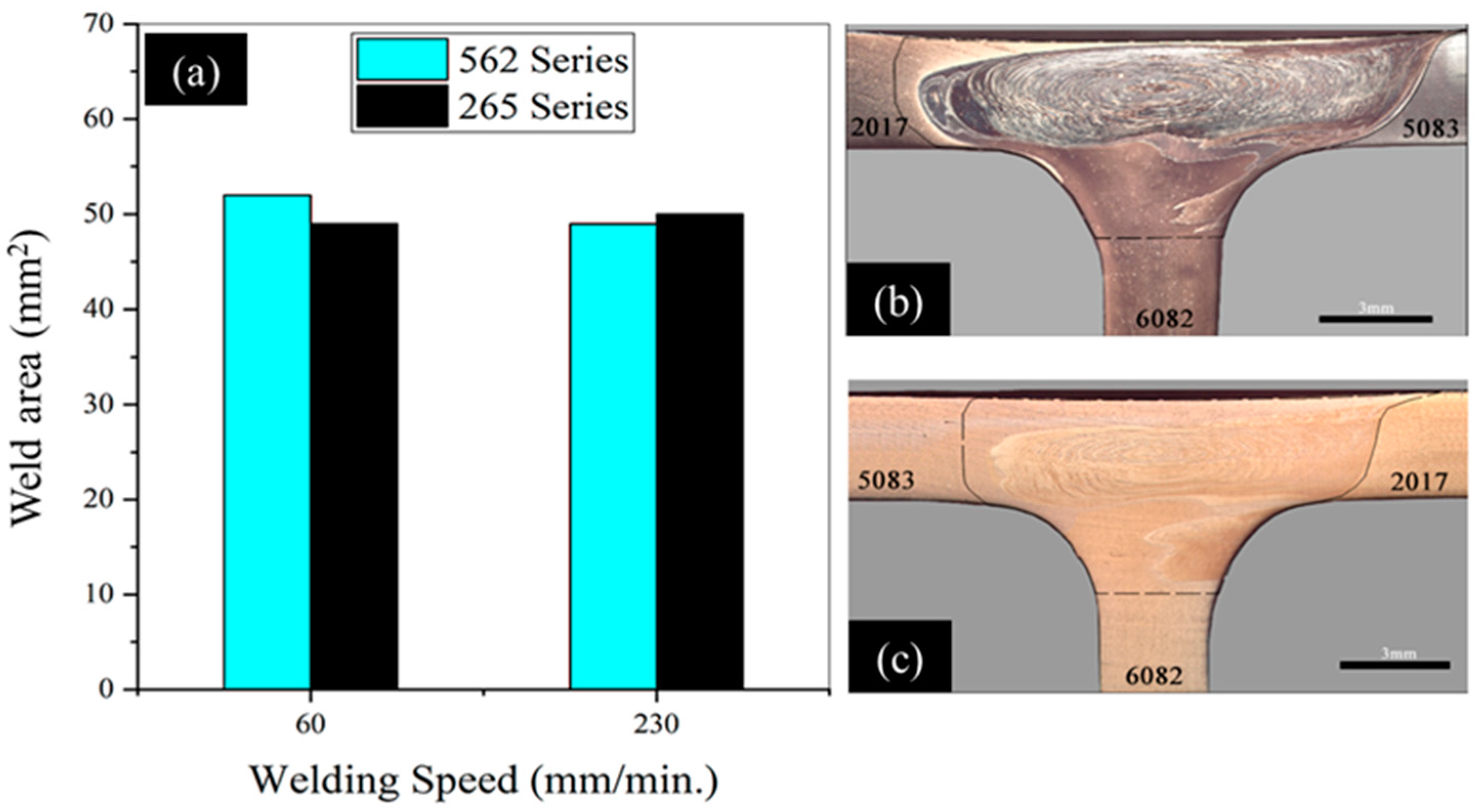
- Placing the stronger alloy on the advancing side leads to higher welding temperature and torque, while increasing the welding speed reduces the peak temperature but increases the torque used;
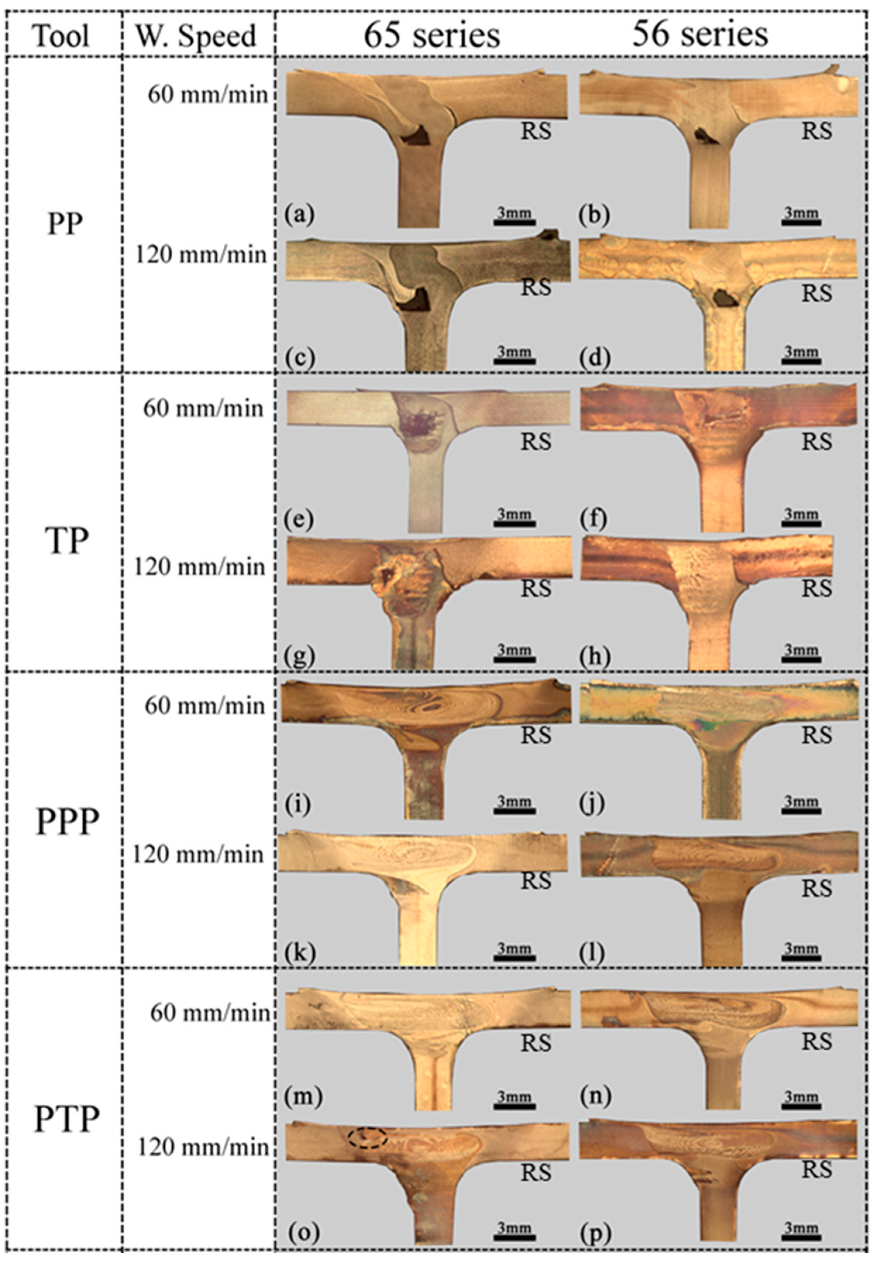
- Single-pin tools do not provide sound welds, unlike progressive pin tools, and this is related to the difference in the temperature and volume of material dragged by the different tools;
- The nugget of the welds has a very refined, but not uniform, grain structure whose size is conditioned by the heat input, but also by the way in which the local plastic deformation of the materials occurs;
- The increase in welding speed causes the appearance of defects in tri-dissimilar welds, even when using a tool with a progressive pin, which causes a reduction in fatigue strength, especially when the more resistant alloy is placed on the advancing side.
Author Contributions
Funding
Institutional Review Board Statement
Informed Consent Statement
Data Availability Statement
Acknowledgments
Conflicts of Interest
References
- Kah, P.; Rajan, R.; Martikainen, J.; Suoranta, R. Investigation of weld defects in friction-stir welding and fusion welding of aluminium alloys. Int. J. Mech. Mater. Eng. 2015, 10, 26. [Google Scholar] [CrossRef] [Green Version]
- Choi, W.J.; Morrow, J.D.; Pfefferkorn, F.E.; Zinn, M.R. The Effects of Welding Parameters and Backing Plate Diffusivity on Energy Consumption in Friction Stir Welding. Procedia Manuf. 2017, 10, 382–391. [Google Scholar] [CrossRef]
- Khan, N.K.; Bajaj, D.; Siddiquee, A.N.; Khan, Z.A.; Abidi, M.H.; Umer, U.; Alkhalefah, H. Investigation on Effect of Strain Rate and Heat Generation on Traverse Force in FSW of Dissimilar Aerospace Grade Aluminium Alloys. Materials 2019, 12, 1641. [Google Scholar] [CrossRef] [Green Version]
- Zhang, Y.; Sato, Y.S.; Kokawa, H.; Park, S.H.C.; Hirano, S. Grain structure and microtexture in friction stir welded commercial purity titanium. Sci. Technol. Weld. Join. 2010, 15, 500–505. [Google Scholar] [CrossRef]
- Derazkola, H.A.; Simchi, A. An investigation on the dissimilar friction stir welding of T-joints between AA5754 aluminum alloy and poly(methyl methacrylate). Thin-Walled Struct. 2019, 135, 376–384. [Google Scholar] [CrossRef]
- Lambiase, F.; Paoletti, A.; Di Ilio, A. Forces and temperature variation during friction stir welding of aluminum alloy AA6082-T6. Int. J. Adv. Manuf. Technol. 2018, 99, 337–346. [Google Scholar] [CrossRef]
- Sreenivas, P.; Anil Kumar, R.; Sreejith, P.S. Effect of applied axial force on FSW of AA 6082-T6 aluminium alloys. Int. J. Mech. Eng. Technol. 2017, 8, 88–99. [Google Scholar]
- Yan, J.; Sutton, M.A.; Reynolds, A.P. Process-structure-property relationships for nugget and heat affected zone regions of AA2524-T351 friction stir welds. Sci. Technol. Weld. Join. 2005, 10, 725–736. [Google Scholar] [CrossRef]
- Arora, A.; Nandan, R.; Reynolds, A.P.; DebRoy, T. Torque, power requirement and stir zone geometry in friction stir welding through modeling and experiments. Scr. Mater. 2009, 60, 13–16. [Google Scholar] [CrossRef]
- Leitão, C.; Louro, R.; Rodrigues, D.M. Using torque sensitivity analysis in accessing Friction Stir Welding/Processing conditions. J. Mater. Process. Technol. 2012, 212, 2051–2057. [Google Scholar] [CrossRef]
- Mehta, M.; Chatterjee, K.; De, A. Monitoring torque and traverse force in friction stir welding from input electrical signatures of driving motors. Sci. Technol. Weld. Join. 2013, 18, 191–197. [Google Scholar] [CrossRef]
- Papahn, H.; Bahemmat, P.; Haghpanahi, M.; Pour Aminaie, I. Effect of friction stir welding tool on temperature, applied forces and weld quality. IET Sci. Meas. Technol. 2015, 9, 475–484. [Google Scholar] [CrossRef]
- Andrade, D.G.; Leitão, C.; Dialami, N.; Chiumenti, M.; Rodrigues, D.M. Modelling torque and temperature in friction stir welding of aluminium alloys. Int. J. Mech. Sci. 2020, 182, 105725. [Google Scholar] [CrossRef]
- Barbini, A.; Carstensen, J.; Dos Santos, J.F. Influence of Alloys Position, Rolling and Welding Directions on Properties of AA2024/AA7050 Dissimilar Butt Weld Obtained by Friction Stir Welding. Metals 2018, 8, 202. [Google Scholar] [CrossRef] [Green Version]
- Cavaliere, P.; De Santis, A.; Panella, F.; Squillace, A. Effect of welding parameters on mechanical and microstructural properties of dissimilar AA6082–AA2024 joints produced by friction stir welding. Mater. Des. 2009, 30, 609–616. [Google Scholar] [CrossRef]
- Abd Elnabi, M.M.; Elshalakany, A.B.; Abdel-Mottaleb, M.M.; Osman, T.A.; El Mokadem, A. Influence of friction stir welding parameters on metallurgical and mechanical properties of dissimilar AA5454–AA7075 aluminum alloys. J. Mater. Res. Technol. 2019, 8, 1684–1693. [Google Scholar] [CrossRef]
- Jesus, J.S.; Costa, J.M.; Loureiro, A.; Ferreira, J.M. Assessment of friction stir welding aluminium T-joints. J. Mater. Process. Technol. 2018, 255, 387–399. [Google Scholar] [CrossRef]
- Astarita, A.; Squillace, A.; Scala, A.; Prisco, A. On the Critical Technological Issues of Friction Stir Welding T-Joints of Dissimilar Aluminum Alloys. J. Mater. Eng. Perform. 2012, 21, 1763–1771. [Google Scholar] [CrossRef]
- -Tavares, S.M.O.; Castro, R.A.S.; Richter Trummer, V.; Vilaça, P.; Moreira, P.M.G.P.; de Castro, P.M.S.T. Friction stir welding of T-joints with dissimilar aluminium alloys: Mechanical joint characterisation. Sci. Technol. Weld. Join. 2010, 15, 312–318. [Google Scholar] [CrossRef]
- Manuel, N.; Galvão, I.; Leal, R.M.; Costa, J.D.; Loureiro, A. Nugget Formation and Mechanical Behaviour of Friction Stir Welds of Three Dissimilar Aluminum Alloys. Materials 2020, 13, 2664. [Google Scholar] [CrossRef]
- Manuel, N.; Silva, C.; Moreira, J.; Loureiro, A. Friction stir welding of T-joints in dissimilar materials: Influence of tool geometry and materials properties. Mater. Res. Express. 2019, 6, 106528. [Google Scholar] [CrossRef]
- Manuel, N.; Costa, J.M.; Loureiro, A. Effect of Material Properties and Process Parameters on Morphology and Strength of Friction-Stir-Welded Dissimilar T-Joints. J. Mater. Eng. Perform. 2019, 28, 5233–5244. [Google Scholar] [CrossRef]
- Abnar, B.; Kazeminezhad, M.; Kokabi, A.H. Effects of heat input in friction stir welding on microstructure and mechanical properties of AA3003-H18 plates. Trans. Nonferrous. Met. Soc. China 2015, 25, 2147–2155. [Google Scholar] [CrossRef]
- ASTM. E8/E8M-16a, Standard Test Methods for Tension Testing of Metallic Materials; ASTM International: West Conshohocken, PA, USA, 2016. [Google Scholar]
- Leitão, C.; Galvão, I.; Leal, R.M.; Rodrigues, D.M. Determination of local constitutive properties of aluminium friction stir welds using digital image correlation. Mater. Des. 2012, 33, 69–74. [Google Scholar] [CrossRef]
- Schmidt, H.; Hattel, J.; Wert, J. An analytical model for the heat generation in friction stir welding. Model. Simul. Mater. Sci. Eng. 2004, 12, 143–157. [Google Scholar] [CrossRef]
- Siddiqui, M.A. Effect of Process Parameters on Temperature Distribution, Strain Rate and Flow-Stress During Friction Stir Welding of Aluminium Alloy. Int. J. Res. Eng. Technol. 2016, 5, 26–32. [Google Scholar] [CrossRef]
- Galvão, I.; Leitão, C.; Loureiro, A.; Rodrigues, D.M. Study of the welding conditions during similar and dissimilar aluminium and copper welding based on torque sensitivity analysis. Mater. Des. 2012, 42, 259–264. [Google Scholar] [CrossRef]
- Banik, A.; Deb Barma, J.; Saha, S.C. Effect of Threaded Pin Tool for Friction Stir Welding of AA6061-T6 at Varying Traverse Speeds: Torque and Force Analysis. Iran. J. Sci. Technol. Trans. Mech. Eng. 2020, 44, 749–764. [Google Scholar] [CrossRef]
- Aldanondo, E.; Vivas, J.; Álvarez, P.; Hurtado, I. Effect of Tool Geometry and Welding Parameters on Friction Stir Welded Lap Joint Formation with AA2099-T83 and AA2060-T8E30 Aluminium Alloys. Metals 2020, 10, 872. [Google Scholar] [CrossRef]
- Sun, Z.; Wu, C.S. A numerical model of pin thread effect on material flow and heat generation in shear layer during friction stir welding. J. Manuf. Process. 2018, 36, 10–21. [Google Scholar] [CrossRef]
- Su, H.; Xue, L.; Wu, C. Optimizing the tool pin with three flats in friction stir welding of aluminum alloy. Int. J. Adv. Manuf. Technol. 2020, 108, 721–733. [Google Scholar] [CrossRef]
- Guerra, M.; Schmidt, C.; McClure, J.; Murr, L.; Nunes, A. Flow patterns during friction stir welding. Mater. Charact. 2002, 49, 95–101. [Google Scholar] [CrossRef] [Green Version]
- Kadian, A.K.; Biswas, P. The study of material flow behaviour in dissimilar material FSW of AA6061 and Cu-B370 alloys plates. J. Manuf. Process. 2018, 34, 96–105. [Google Scholar] [CrossRef]
- McNelley, T.R.; Swaminathan, S.; Su, J.Q. Recrystallization mechanisms during friction stir welding/processing of aluminum alloys. Scr. Mater. 2008, 58, 349–354. [Google Scholar] [CrossRef] [Green Version]
- Jonckheere, C.; De Meester, B.; Denquin, A.; Simar, A. Torque, temperature and hardening precipitation evolution in dissimilar friction stir welds between 6061-T6 and 2014-T6 aluminum alloys. J. Mater. Process. Technol. 2013, 213, 826–837. [Google Scholar] [CrossRef]
- Neto, D.M.; Neto, P. Numerical modeling of friction stir welding process: A literature review. Int. J. Adv. Manuf. Technol. 2013, 65, 115–126. [Google Scholar] [CrossRef] [Green Version]
- Ackiel, M. Effect of Friction Stir Welding Parameters on Fatigue Resistance, Weld Quality and Mechanical Properties of Al 6061-T651. J. Mech. Eng. 2017, 2, 83–99. [Google Scholar]


| Alloys | Cu | Mg | Mn | Fe | Si | Zn | Ti |
|---|---|---|---|---|---|---|---|
| AA2017-T4 | 4.5 | 0.8 | 1.0 | 0.7 | 0.8 | 0.25 | 0.15 |
| AA5083-H111 | 0.025 | 4.5 | 0.57 | 0.18 | 0.09 | 0.01 | 0.01 |
| AA6082-T6 | 0.09 | 0.6 | 1.0 | 0.44 | 0.81 | 0.08 | 0.03 |
| Properties | AA2017-T4 | AA5083-H111 | AA6082-T6 |
|---|---|---|---|
| Ultimate tensile strength (MPa) | 427.0 | 317.5 | 321.0 |
| Tensile yield strength (MPa) | 276.0 | 158.0 | 288.0 |
| Elongation at failure (%) | 22.0 | 10.4 | 8.6 |
| Vickers hardness (HV 0.2) | 118.0 | 83.5 | 116.0 |
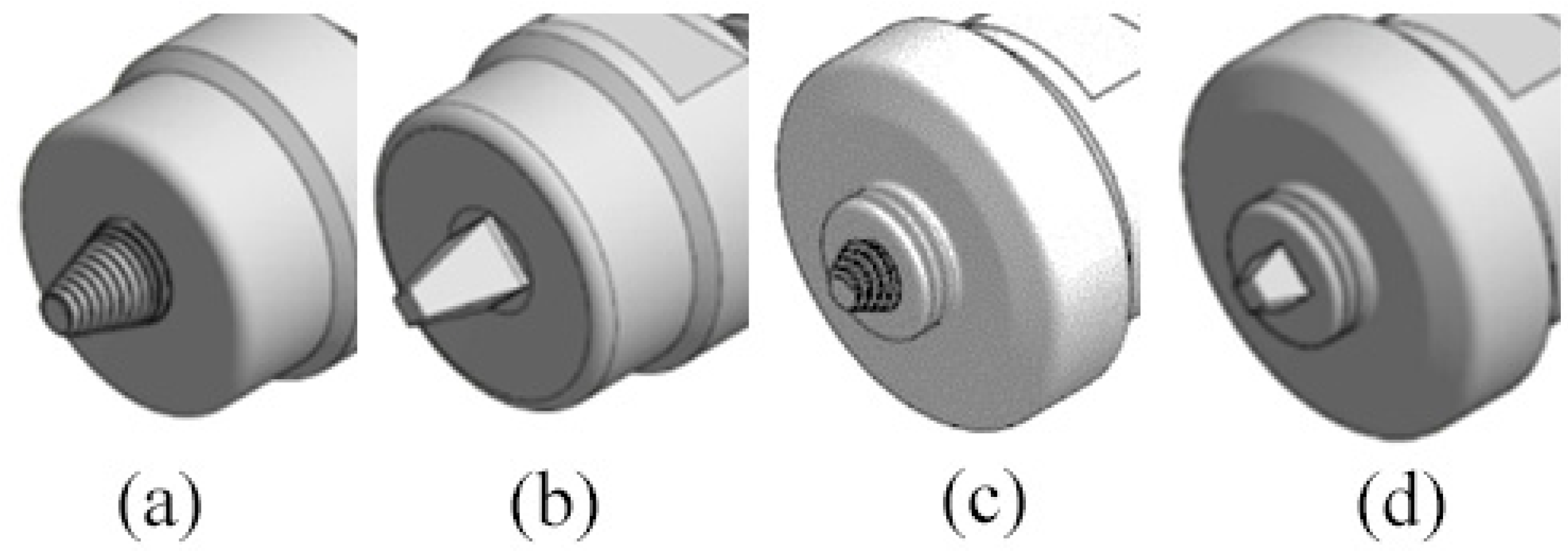
| Tool pin geometry | 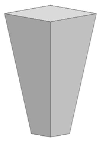 | 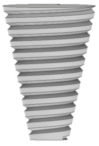 | 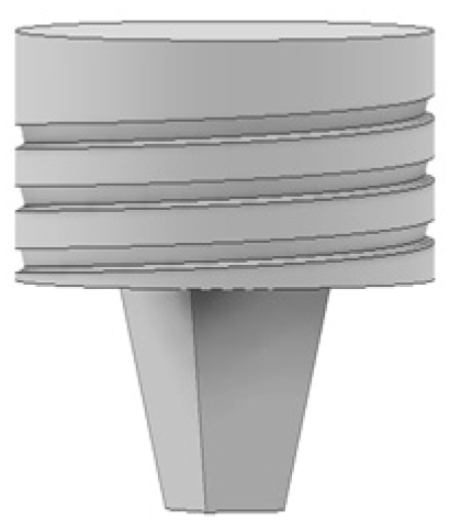 | 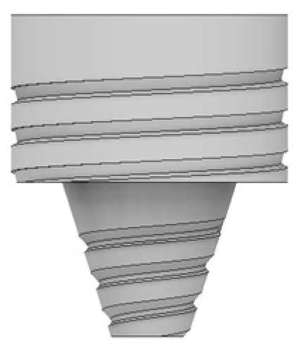 |
| Volume (mm3) | 55.33 | 86.08 | 188.97 | 198.8 |
| Friction area (mm2) | 92.4 | 114.12 | 245.36 | 258.13 |
| Welds | Tool | Rotation Speed (rpm) | Traverse Speed (mm/min) |
|---|---|---|---|
| 65P-60 | PP | 500 | 60 |
| 65P-120 | 120 | ||
| 56P-60 | 60 | ||
| 56P-120 | 120 | ||
| 65T-60 | TP | 500 | 60 |
| 65T-120 | 120 | ||
| 56T-60 | 60 | ||
| 56T-120 | 120 | ||
| 65PP-60 | PPP | 500 | 60 |
| 65PP-120 | 120 | ||
| 56PP-60 | 60 | ||
| 56PP-120 | 120 | ||
| 65TP-60 | PTP | 500 | 60 |
| 65TP-120 | 120 | ||
| 56TP-60 | 60 | ||
| 56TP-120 | 120 |
| Welds | Tool | Rotation Speed (rpm) | Traverse Speed (mm/min) |
|---|---|---|---|
| 562TP-60 | PTP | 500 | 60 |
| 562TP-230 | 230 | ||
| 265TP-60 | PTP | 500 | 60 |
| 265TP-230 | 230 |
| Weld | UTS [MPa] | Strength Efficiency [%] | Zone of Fracture |
|---|---|---|---|
| 562TP-60 | 295.7 | 93.7 | HAZ (AA5083) |
| 562TP-230 | 304.4 | 96.1 | HAZ (AA5083) |
| 265TP-60 | 295.6 | 93.2 | HAZ (AA5083) |
| 265TP-230 | 263.2 | 82.8 | HAZ (AA5083) |
| Series | Line Equation | Fatigue Strength at 106 Cycles (MPa) | Slope “m” | R2 |
|---|---|---|---|---|
| 562TP-60 | σ = 537.98 N−0.09 | 155.16 | 11.11 | 0.79 |
| 562TP-230 | σ = 692.67 N−0.127 | 119.82 | 7.87 | 0.66 |
| 265TP-60 | σ = 554.29 N−0.09 | 159.86 | 11.11 | 0.78 |
| 265TP-230 | σ = 365.6 N−0.1 | 91.39 | 9.90 | 0.55 |
| AA5083 | σ = 653.15 N−0.095 | 175.80 | 10.53 | 0.89 |
Publisher’s Note: MDPI stays neutral with regard to jurisdictional claims in published maps and institutional affiliations. |
© 2021 by the authors. Licensee MDPI, Basel, Switzerland. This article is an open access article distributed under the terms and conditions of the Creative Commons Attribution (CC BY) license (https://creativecommons.org/licenses/by/4.0/).
Share and Cite
Manuel, N.; Beltrão, D.; Galvão, I.; Leal, R.M.; Costa, J.D.; Loureiro, A. Influence of Tool Geometry and Process Parameters on Torque, Temperature, and Quality of Friction Stir Welds in Dissimilar Al Alloys. Materials 2021, 14, 6020. https://doi.org/10.3390/ma14206020
Manuel N, Beltrão D, Galvão I, Leal RM, Costa JD, Loureiro A. Influence of Tool Geometry and Process Parameters on Torque, Temperature, and Quality of Friction Stir Welds in Dissimilar Al Alloys. Materials. 2021; 14(20):6020. https://doi.org/10.3390/ma14206020
Chicago/Turabian StyleManuel, Neves, Daniel Beltrão, Ivan Galvão, Rui M. Leal, José D. Costa, and Altino Loureiro. 2021. "Influence of Tool Geometry and Process Parameters on Torque, Temperature, and Quality of Friction Stir Welds in Dissimilar Al Alloys" Materials 14, no. 20: 6020. https://doi.org/10.3390/ma14206020
APA StyleManuel, N., Beltrão, D., Galvão, I., Leal, R. M., Costa, J. D., & Loureiro, A. (2021). Influence of Tool Geometry and Process Parameters on Torque, Temperature, and Quality of Friction Stir Welds in Dissimilar Al Alloys. Materials, 14(20), 6020. https://doi.org/10.3390/ma14206020