Article

Analysis of the Quality of Sulfomolybdenum Coatings Obtained by Electrospark Alloying Methods

by
Oksana P. Gaponova
1,*,
Bogdan Antoszewski
2,
Viacheslav B. Tarelnyk
3,
Piotr Kurp
2,*,
Oleksandr M. Myslyvchenko
4 and
Nataliia V. Tarelnyk
5
1
Applied Material Science and Technology of Constructional Materials Department, Sumy State University, 40007 Sumy, Ukraine
2
Laser Research Centre, Faculty of Mechatronics and Mechanical Engineering, Kielce University of Technology, Al. Tysiąclecia P.P. 7, 25-314 Kielce, Poland
3
Technical Service Department, Sumy National Agrarian University, H. Kondratiieva Str. 160, 40021 Sumy, Ukraine
4
Department of Physical Chemistry of Inorganic Materials, Frantsevich Institute for Problems of Materials Science, Krzhizhanovsky Str. 3, 03142 Kyiv, Ukraine
5
Projection of Technical System Department, Sumy National Agrarian University, H. Kondratiieva Str. 160, 40021 Sumy, Ukraine
*
Authors to whom correspondence should be addressed.
Materials 2021, 14(21), 6332; https://doi.org/10.3390/ma14216332
Submission received: 5 October 2021 / Revised: 14 October 2021 / Accepted: 16 October 2021 / Published: 23 October 2021

Abstract

:
The authors of this paper have attempted to improve the quality of surface layers applied to steel elements of machine parts constituting friction couples. The main goal of the research was to investigate an electrospark alloying method process for obtaining abrasion-resistant tribological coatings containing molybdenum disulfide on a steel surface. A substance in the form of sulfur ointment with a sulfur content of 33.3% was applied on the surfaces of C22 and C40 steel specimens. In order to determine the influence of the energy parameters of ESA equipment on the quality parameters of coatings, the ESA process was carried out using a molybdenum electrode with discharge energies Wp = 0.13; Wp = 0.55; Wp = 3.4 J. The following tests were carried out on specimens with such coatings: metallographic analysis, microhardness tests, surface roughness, and local X-ray diffraction microanalysis. The experiments revealed that sulfomolybdenum coatings consist of four zones with different mechanical properties. Depending on the discharge energy and the substrate material, the hardness of these zones varies from approx. 1100 to over 10,000 MPa. Differences in the distribution of, among others, sulfur and molybdenum in the obtained coatings, as well as differences in the microstructure of the observed coatings, were observed.

1. Introduction

Wear of contact joint parts, in particular of antifriction purpose, is a cause of unbalance of machine units due to changes in the sizes of the worn parts thereof, which results in equipment operation instability, loss of productivity, and reduced product quality [1,2]. The authors [3,4] have proven that the amount and term of overhaul work depend on friction connections in 70% of cases. Reducing friction and, therefore, wear of metal surfaces in the places of interactions of main component parts of machines and mechanisms is an urgent problem of modern science and technology.
There is a solid lubricant, namely molybdenum disulfide MoS2 [5,6], which is chemically and thermally stable up to 600 °C, and this property guarantees the above solid lubricant presence in its unchanged form in a composite material both while manufacturing and also operating. Just molybdenum disulfide is an effective lubricant in the air under light-duty or reasonable operating conditions of parts [7].
It is well known that to increase the wear resistance of machine parts, oils and lubricants laced with antifriction additives are used. One such antifriction additive is molybdenum disulfide (MoS2). Hexagonal MoS2 crystals have a layered structure. The Mohs scale molybdenum disulfide hardness is 1.0–1.5. It has a high chemical stability and resistance to most acids and radioactive irradiation. In a vacuum, molybdenum disulfide (MoS2) decomposes into molybdenum and sulfur at 1100 °C [8].
The lubricating properties of molybdenum disulfide are provided by its crystalline structure: Van der Waals bonds between the sulfur layers allow the latter to freely move, which results in reduced friction. On the other hand, the ionic bonds between Mo and S impart high strength to the layers, so they are able to resist punching performed by the microprotrusions of the friction surfaces. The 2.5-μm-thick lubricating layer contains 4000 layers of (S-Mo-S) (see Figure 1). The sulfur layers, which form the surface of a molybdenum disulfide crystal, provide strong adhesion to a metal surface [9,10].
At present, micron-sized powders of naturally layered molybdenum disulfide are widely used as solid lubricants and effective additives to oils and lubricating substances in order to improve their tribological properties. Advances in nanotechnology have stimulated the development of research on the processes and mechanisms of wear with the participation of nanocrystalline compounds, as well as comparisons of traditional concepts of lubrication and “nano-lubrication” [11,12]. When using solid lubricants, namely molybdenum trisulfide (Mo3) nanoparticles, there appears to be a positive effect on the improvement of the tribological properties of lubricants [13,14,15].
The interaction of Mo molybdenum with S sulfur is the subject of a long-term investigation. As follows from Figure 1, which shows the phase diagram of the Mo-S system at atmospheric pressure, where G is a gas and L is a liquid solution [16], in the Mo-S system, two stable molybdenum sulfides (Mo2S3 and MoS2) are formed, which can be directly obtained from the elements. The Mo2S3 phase is not stable at temperatures below 610 °C. In the phase of MoS2, up to 69% (at.) of S sulfur can be dissolved at 1000 °C. The melting point of MoS2 is above 1800 °C. The solubility of S in Mo reaches 1.5% (at.) at 1100 °C.
There has been prior research on thesulfo-cyanidation of electrodeposited Fe-Mo coatings [17]. The authors experimentally set the most rational sulfo-cyaniding medium, namely, a pasty coating for parts, consisting of 35–40% potassium hexacyanoferrate (II), 15–20% sulfur pyrite, 5–8% fire-clay grog, and 25–30% soot with a binder (i.e., starch glue). The process of sulfo-cyanidation is carried out at temperatures of 550 to 600 °C, which allows for a wear-resistant coating with a surface carbonitrided zone saturated with iron sulfides and molybdenum disulfide to be obtained. However, this technology is environmentally unsafe.
In [18], a new technology for forming a package of flexible elements for an elastic coupling was developed. The additional incorporation of molybdenum disulfide into the metal-cladding lubricant, which consists of paraffin and copper powder, allows for the fretting resistance of the flexible elements to be increased by ~2.5 and 1.1 times, respectively, as compared with the flexible elements without any lubricant and those with a metal-cladding lubricant without molybdenum disulfide.
In [19], one of the ways to increase the level of the operational reliability of diesel fuel equipment, namely the plunger pairs of the fuel pumps, is presented. A technological approach in restoring the efficiency of parts by applying thereon an antifriction coating containing molybdenum disulfide with the use of a vacuum-plasma spraying method is presented. Applying this technology allows the operational properties of the plunger pair component parts to be increased, as well as their resource.
Furthermore, there are known methods for chemical heat treatment (CHT), which, at sequentially or simultaneously saturating steel surfaces with Mo and S, allow sulfomolybdenum coatings to be obtained [20,21].
Despite the fact that the CHT method significantly improves the quality of the machine parts’ surface layers, the above method has a number of disadvantages:
  • there is volumetric heating of the parts, resulting in the occurrence of changes in their structures and initial geometric parameters (deformations and curvatures);
  • there is a need for bulky and expensive technological equipment;
  • there is a long process duration;
  • there is high energy consumption;
  • there are issues regarding marginal cost;
  • there are environmental- and technogenic-related concerns, etc.
There is a method of electrospark alloying (ESA) that is becoming more widely used in industry to increase the wear resistance and hardness of the surfaces of machine component parts, including those operating in conditions of elevated temperatures and aggressive environments [22,23].
The surface ESA is a process of transferring a curtain material to the treated surface by spark electric discharge. The method has a number of specific features:
  • An anode material (an alloying one) can form a coating layer on the surface of the cathode (the surface being alloyed), with the coating layer being extremely tightly adhered to the above surface. In this case, not only is there an absence of an interface between the deposited material and the base metal, but there is also an even diffusion of the anode elements into the cathode;
  • The alloying process can be carried out in specified places (with the radius range starting from particles the size of a millimeter and larger) without protecting the rest of the surface of the part being alloyed;
  • The application ofthe ESAmethod on metal surfaces is very simple, and the necessary equipment is compact and transportable [24].
The ESA method expands the possibilities of obtaining tribological coatings. In [25], a process for applying a wear-resistant antifriction coating on the working surface of a piston ring is described. It consists of obtaining a coating of molybdenum of a thickness of 30 μm, microhardness of 6400 MPa, and roughness of Rz 1.5 to 1.1 μm. The alloyed surface is subjected to manual sanding with sandpaper and coating with copper. Furthermore, the surface obtained is treated by the method of surface plastic deformation followed by the application of a consistent lubricant, which contains molybdenum disulfide and graphite, to improve the friction unit’s running-in ability. However, this technology has significant drawbacks, including an increase in the number of technological operations, the presence of the lubricant on the surfaces being treated, and the risk of contamination of the working environment of the part, which is extremely undesirable, for example, in the friction units of equipment for the textile and food industries, etc.
There is a process of sulfocarburizing a steel product surface by the method of electroerosion alloying (EEA) with the use of a graphite electrode, wherein immediately before alloying with the graphite electrode, a grease lubricant containing sulfur is applied onto the steel surface [26]. The main disadvantages of this method are as follows:
  • there is an inability to form molybdenum disulfide on the surface of the parts;
  • there is a decreased possibility of reducing the coefficient of friction;
  • there is insufficiently high running-in and wear resistance within the friction pairs, especially without lubrication.
We have proposed a method for sulfomolybdenum metal surfaces, which include materials coated with a substance in the form of a sulfur ointment and electrospark alloying with a molybdenum electrode. In our opinion, this technology will make it possible to obtain self-lubricating coatings, as in [26], and to provide special tribotechnical properties (for example, a low coefficient of friction).
Thus, the aim of the present work is to improve the quality of the surface layers of steel parts involved in friction pairs. The problem has been solved by developing a process for obtaining wear-resistant tribological coatings, which contain molybdenum disulfide, on the steel surfaces by applying the method of electrospark alloying.

2. Materials and Methods

To determine the influence of the energy parameters of ESA equipment on the quality parameters of coatings, specimens sized 15 × 15 × 8 mm and made of C22 steel and C40 steel were coated with a substance in the form of a sulfur ointment with a sulfur content of 33.3%. After that, the ESA process was performed using a molybdenum electrode of 4 mm diameter and 45 mm length using the Elitron—52A unit under the ESA operating modes at discharge energy Wp = 0.13; 0.55; 3.4 J. Each ESA operating mode corresponded to its discharge energy and productivity, namely, the area of the formed coating per time unit (see Table 1).
The metallographic analysis of the coatings was carried out using the MIM-7 optical microscope (LOMO, Saint Petersburg, USSR); microhardness testing was performed on the PMT-3 instrument (LOMO, Saint Petersburg, USSR) according to standard methods. The surface roughness after ESA was determined by reading and processing the profilograms using the profilograph-profilometer device (Kalibr Instrument Plant, Moscow, Russian Federation) of model 201 manufactured at the “Caliber” plant.
To study the layer depth distribution of the elements, a local X-ray diffraction microanalysis was performed based on the registration of the characteristic X-rays excited by an electron beam of the chemical elements that were available in the microvolume. To this end, a scanning electron microscope of the SEO-SEM Inspect S50-B (FEI Company, Oregon, USA) type equipped with the energy-dispersive spectrometer of the AZtecOne model with the detector of the X-MaxN20 type was applied (Oxford Instruments plc, Abingdon-on-Thames, Great Britain). We used the following parameters: working distance (WD) 10.2 mm, spot size (spot) 6.0, accelerating voltage (HV) 20.00 kV.
The X-ray studies were performed in CoKα-radiation with the use of the diffractometer of the DRON-UM1 model (LNPO “Burevestnik”, St. Petersburg, Russian Federation). The diffractograms were taken by the step-by-step scanning method. The scanning step was 0.050; the exposure time at a point was 3 s. The processing of the diffractograms was performed using a program for the full-scale analysis of X-ray spectra from the mixture of the polycrystalline components of the Powder Cell 2.4 program.

3. Results and Discussion

The metallographic studies and microhardness testing of the coatings showed that the sulfomolybdenum coatings consist of four zones: the upper loose layer of microhardness Hμ = 1112 ÷ 2040 MPa, a strengthened layer called “white” of Hμ = 5147 ÷ 5474 MPa for Wp = 0.13 J, as well as of Hμ = 10596 ÷ 10731 MPa for Wp = 3.4 J, the diffusion zone, and the base metal (see Figure 2, Figure 3, Figure 4 and Figure 5).Upon replacing the substrate of C22 steel with the substrate of C40 steel, an increase in the microhardness and the thickness of the strengthened layer occurs, as well as the continuity thereof (Table 2).
A scanning electron microscope with a microanalysis system was used to study the sulfomolybdenum coatings. The image obtained was examined with the BSE detector of backscattered (reflected) electrons. The above image contains the well-visible and clearly defined areas, which differ in tone color depending on the atomic number of the chemical element. In such images, the light regions are the areas containing the heavier elements (in our case, molybdenum), from which the electrons of the beam are reflected better than from the lighter elements.
The results of the analysis of the surface area, which includes the coating and the fragment of the base metal with the pre-eutectoid structure, showed that the resulting layer has a heterogeneous composition with different concentrations of elements (see Figure 6). Thus, according to the element distribution maps of the areas of the studied specimens (see Figure 7), sulfur is concentrated on the surface and molybdenum is more evenly distributed in the coating.
As a result of the local energy dispersion X-ray microanalysis, the distribution curves of sulfur, molybdenum, and iron were obtained (see Figure 8). It was observed that sulfur and molybdenum were concentrated at depths of up to 4 and 19 μm, respectively, at Wp = 0.13 J; up to 5 and 25 μm, respectively, at Wp = 0.55 J; and up to 15 and 70 μm, respectively, at Wp = 3.4 J.
The X-ray diffraction analysis of the obtained coatings confirmed the results of the energy dispersion analysis (see Figure 9). Thus, at low discharge energies, the phase composition of the coatings on C40 steel was represented by the BCC (body centered cubic) solid solution with a lattice period close to ferrite, martensite, the FCC (face centered cubic) solid solution, and the FeMo intermetallide (σ-phase). Obviously, because of the alloying of the BCC solid solution (ferrite) by sulfur and molybdenum, as well as the processing under the non-equilibrium cooling conditions, the parameter a increased there (see Table 3).
Under conditions of high heating and cooling rates of the surface layer microvolumes, which lead to the formation of nonequilibrium structures, and also as a result of mixing the base material and the material of the alloying electrode, due to the interaction between the liquid alloy bath and the environment, namely air, during the ESA process, as well as owing to the intense shock waves that appear during the ESA process and lead to thermo-mechanical hardening, and other events that influence the phase formation, it is obvious that two alloyed austenites were formed in the surface layer at alloying temperatures greater than 1000 °C. One of them, the Mn martensitic point, which is above room temperature, when cooled, undergoes martensitic transformation, thus forming martensite with lattice parameters a = 2.8740 nm and c = 2.9200 nm. Due to the fact that molybdenum intensively reduces the temperature of martensitic transformation, it is not going to end, and in the coating, there remains the unconverted residual austenite, namely, the FCC solid solution (see Table 3). In addition to the solid solutions, in the surface layer, up to 40% of FeMo intermetallides are formed, which contributes to a significant increase in the microhardness of the surface layer after the ESA process at Wp = 0.55 J (at Wp = 0.13 J, Hμ = 5474 MPa, at Wp = 0.55 J, Hμ = 7832 MPa; see Table 2).
The process of sulfomolybdenization of C40 steel by the ESA method at Wp = 3.4 J leads to an increase in the amount of the martensitic phase of up to 30%, as compared with 11% at Wp = 0.55 J, and to the decrease in the amount of residual austenite (FCC phase) from 25% to 6%, and also in the amount of molybdenum disulfide, which reduces to 5%. It should be noted that with increasing discharge energy, the surface roughness increases, which makes it impossible to obtain reliable results of the X-ray diffraction analysis. Therefore, the diffractograms were processed from the surface after cleaning it with 15-μm sandpaper.
When replacing the substrate made of C40 steel with the substrate made of C22 steel, the sulfomolybdenum coating reveals a smaller amount of the FCC phase, namely the residual austenite, at the same discharge energy (see Figure 10). Molybdenum disulfide is even formed at the discharge energy Wp = 0.55 J (3.77%); and at Wp = 3.4 J, about 8% thereof is found on the surface and about 5% is found at a depth down to 15 μm (see Table 4).

4. Conclusions

The considerable research on the process of sulfomolybdenizing metal surfaces, which consists of applying a paste containing sulfur onto a steel surface being processed and further electrospark alloying thereof by a molybdenum electrode at discharge energies of 0.13; 0.55; 3.4 J, has led to the following conclusions:
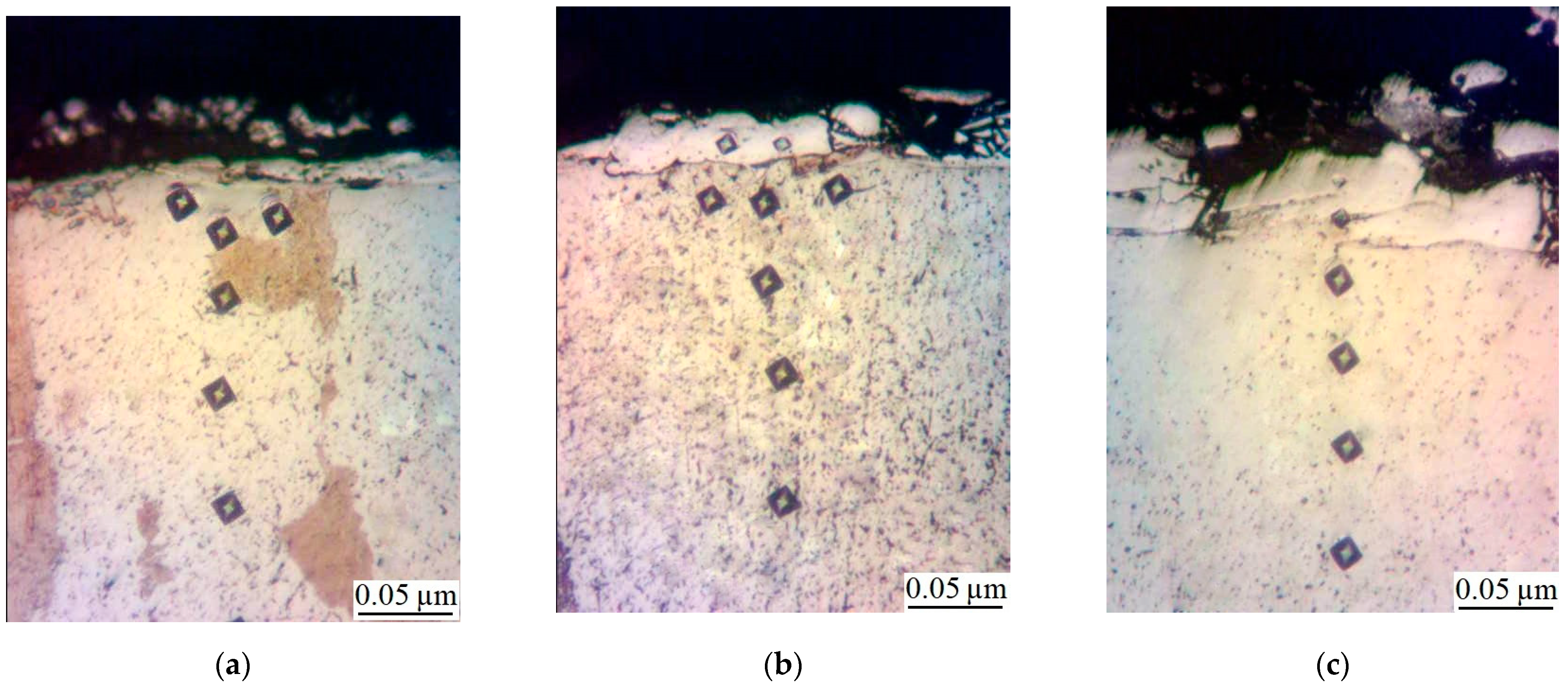
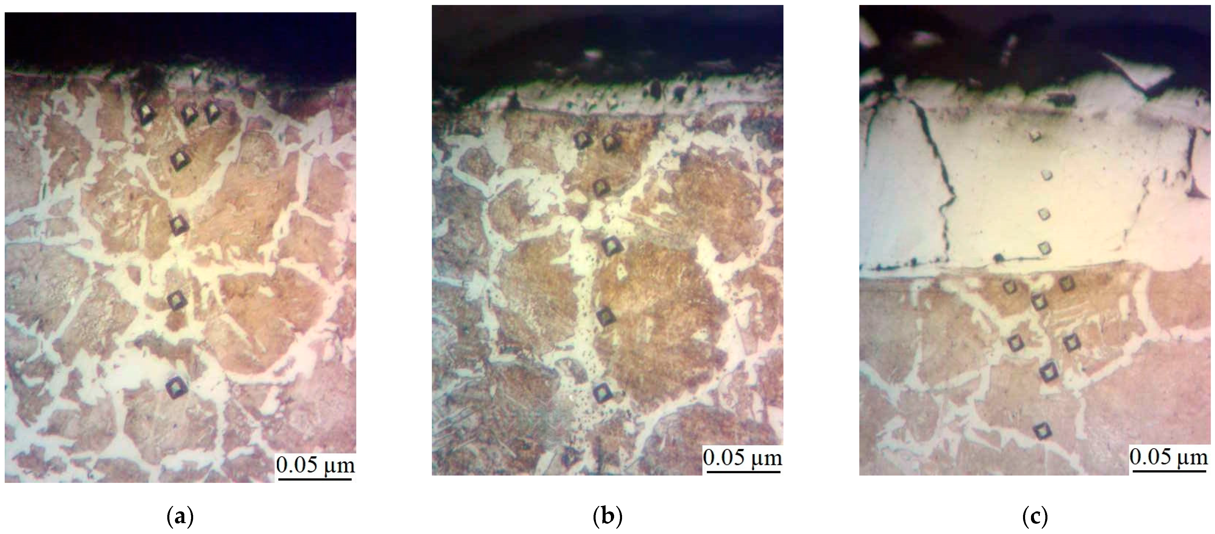
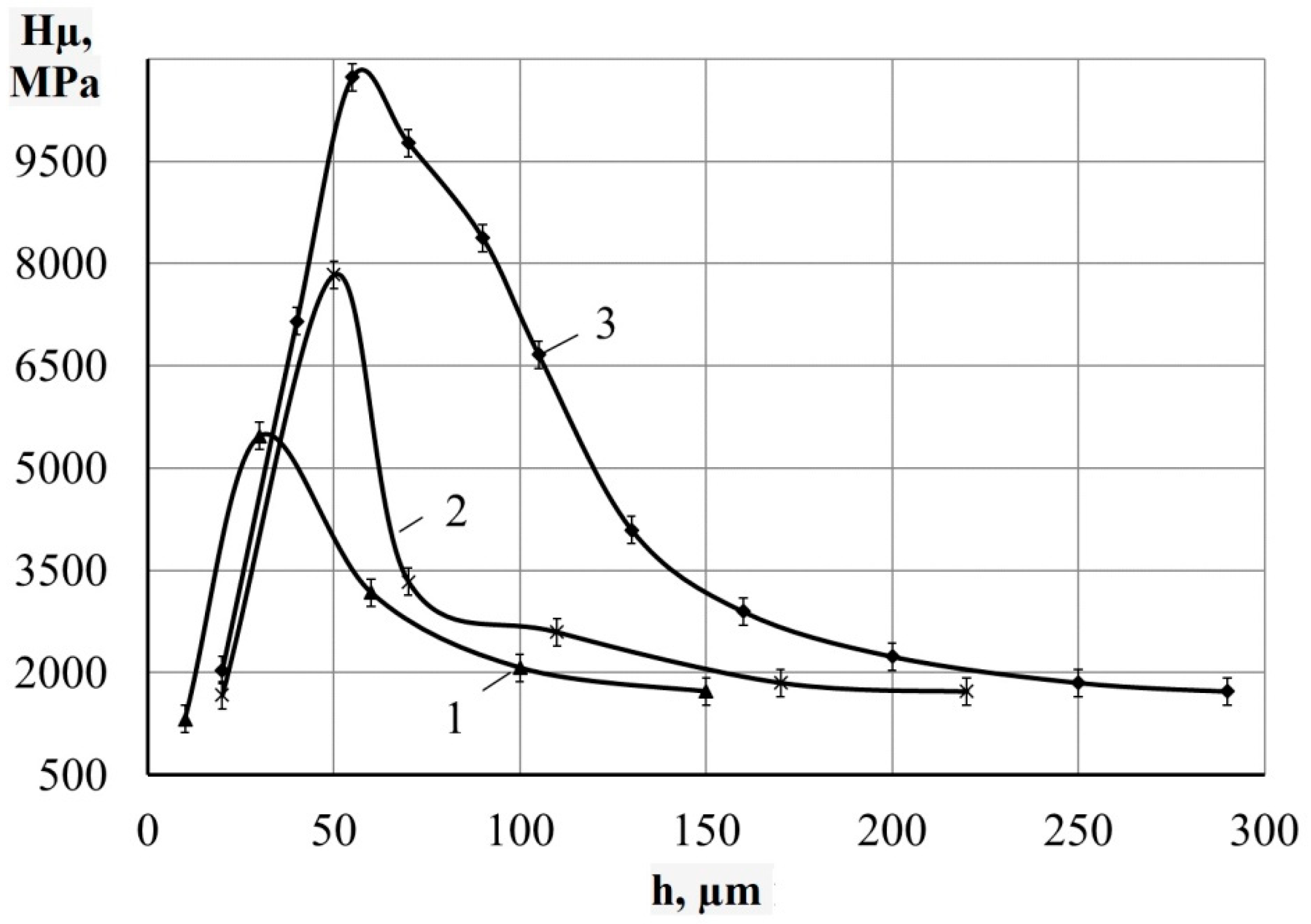
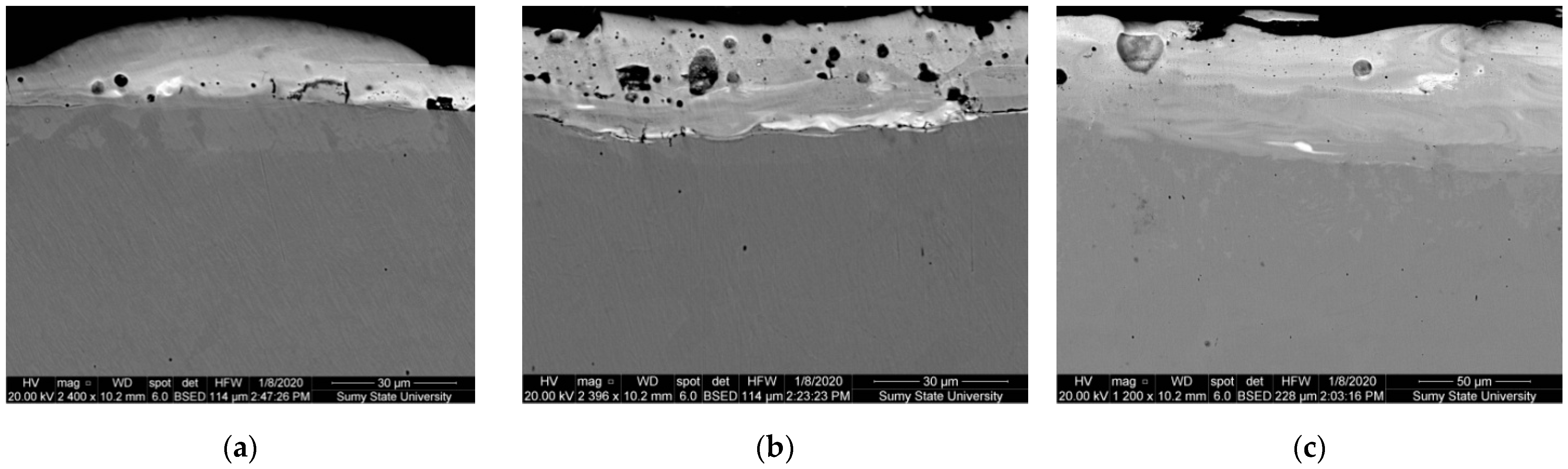
  • Metallographic and durametric studies have shown that the sulfomolybdenum coatings consist of the following four zones:
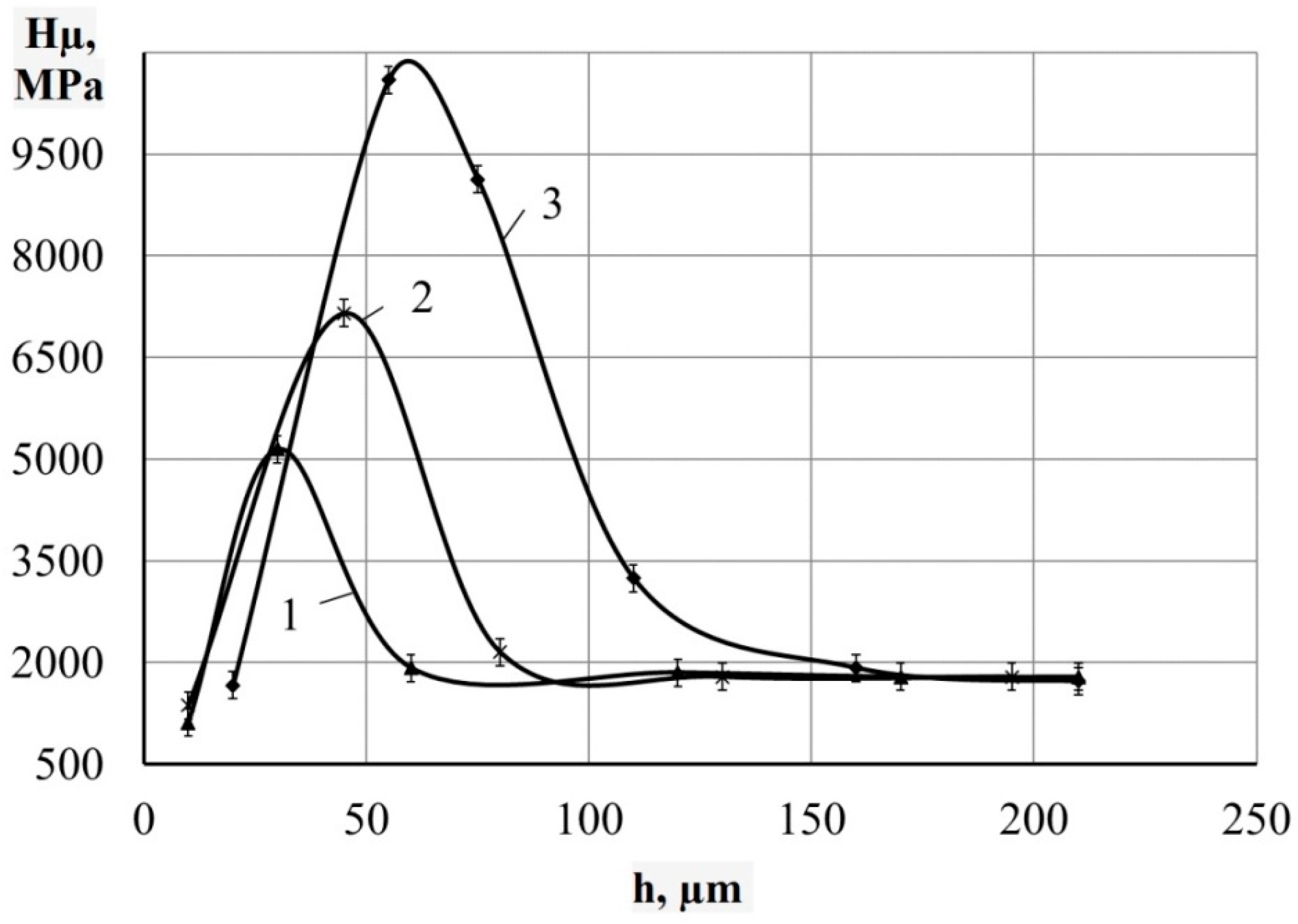
    • the upper loose layer has the microhardness Hμ of 1112 to 2040 MPa;
    • the “white” strengthened layer has the microhardness Hμ of 5147 to 5474 MPa for Wp = 0.13 J and Hμ of 10596 to 10731 MPa for Wp = 3.4 J;
    • the diffusion zone; and
    • he base metal.
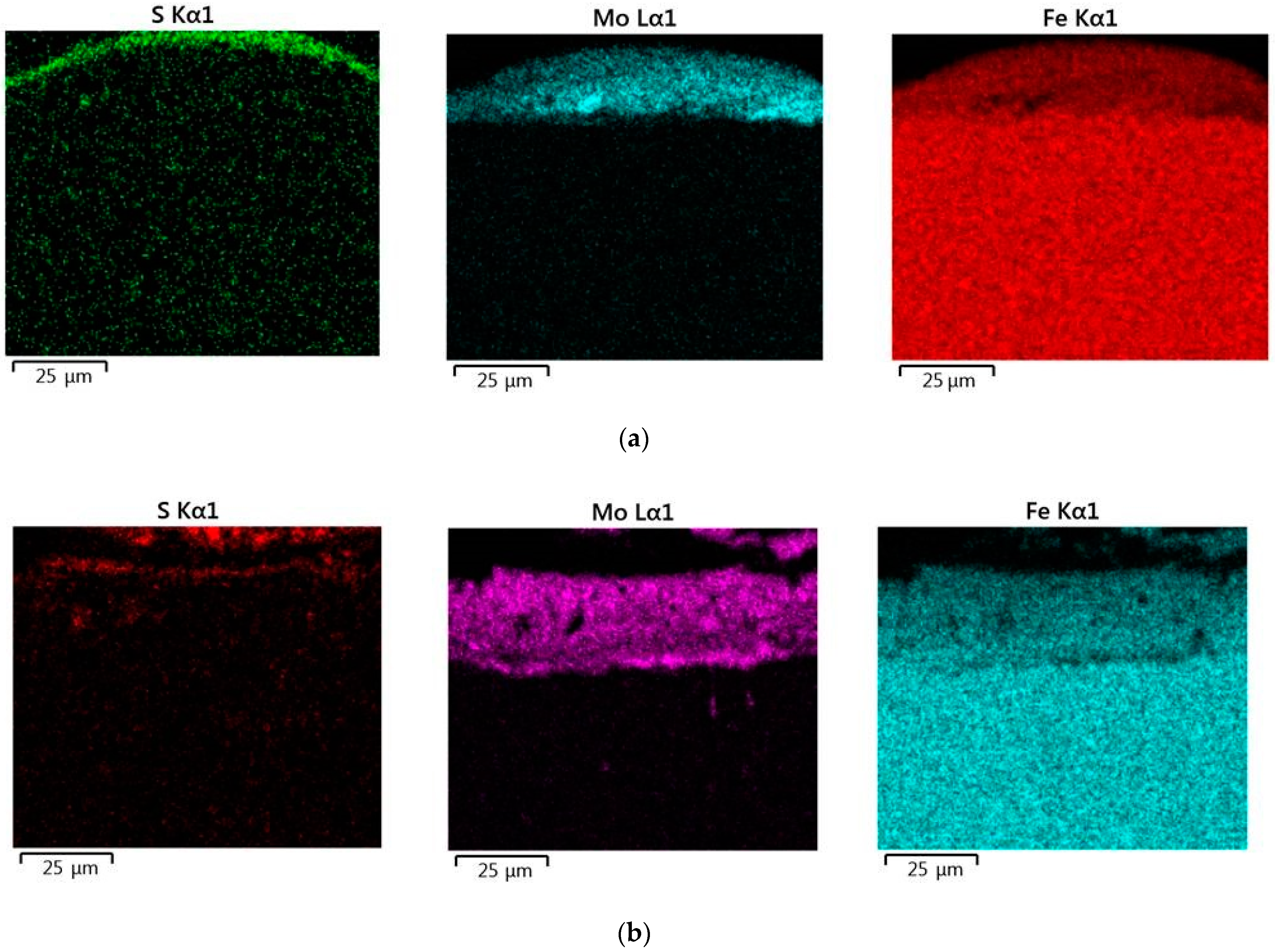
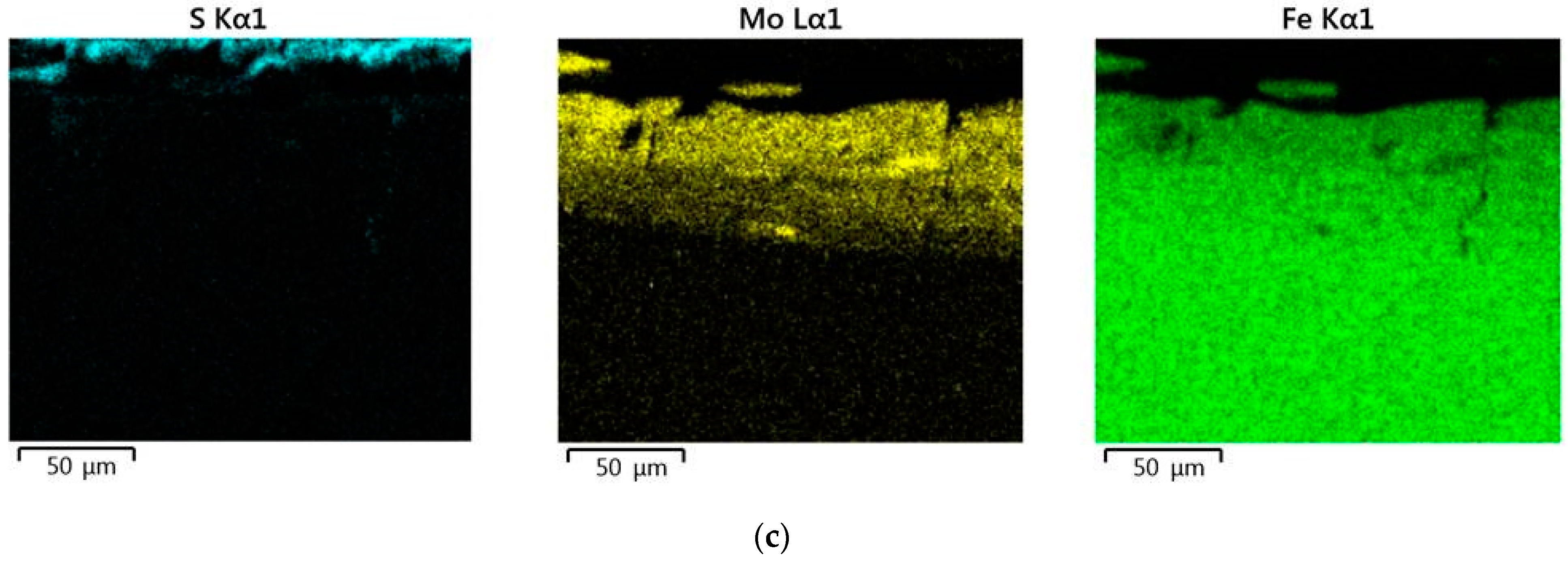
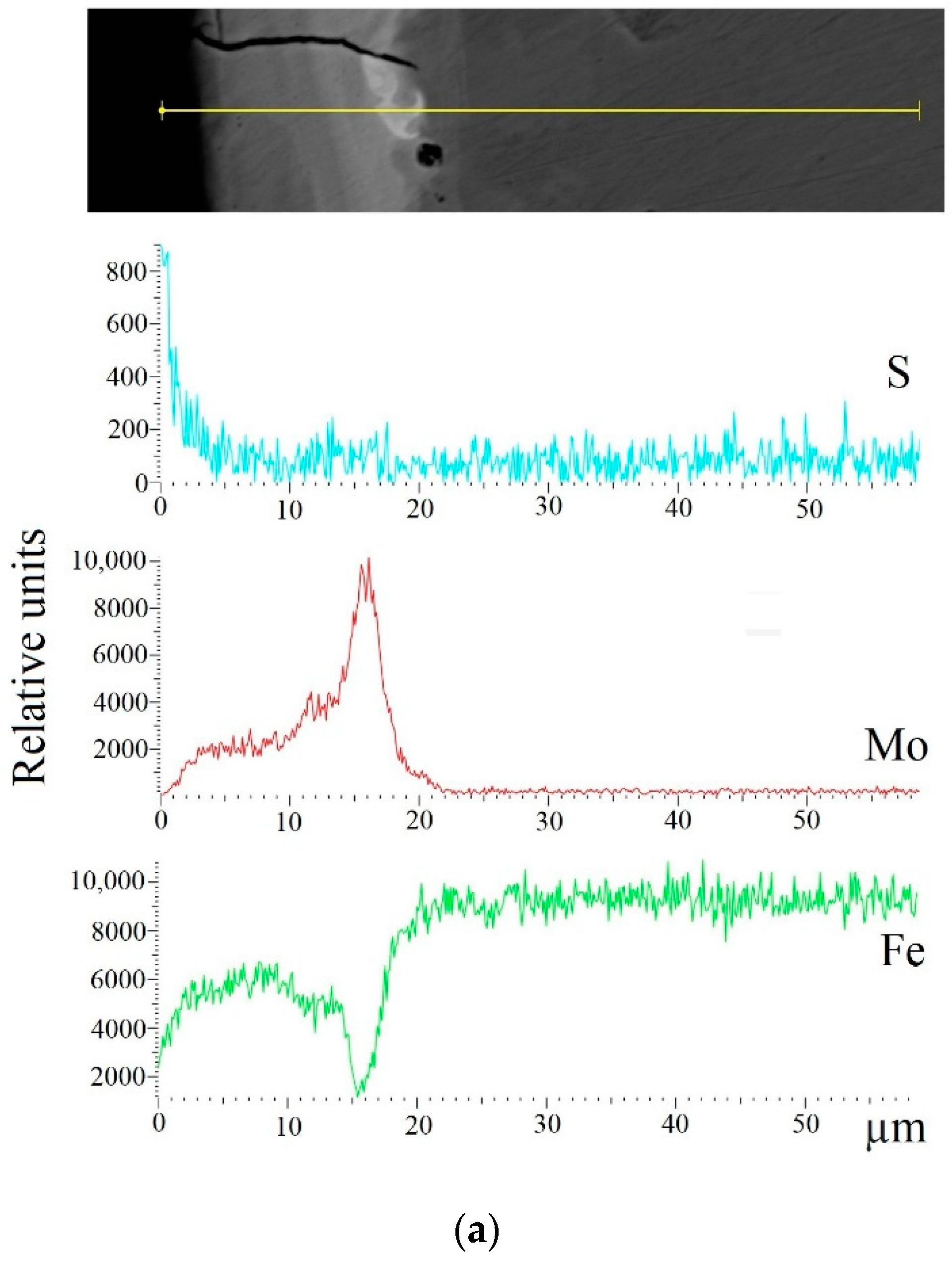
    When replacing the substrate of steel C22 with steel C40, there is an increase in the values of the microhardness, the thickness of the strengthened layer, as well as the continuity thereof.
  • Electron microscopic studies of the obtained coatings showed that the resulting layer has a heterogeneous composition with different concentrations of elements. According to the element distribution maps of the areas of the studied specimens, sulfur is concentrated on the surface and molybdenum is more evenly distributed in the coating. The energy dispersion analysis showed that sulfur and molybdenum are concentrated at depths up to 4 and 19 μm, respectively, at Wp = 0.13 J, up to 5 and 25 μm, respectively, at Wp = 0.55 J, and up to 15 and 70 μm, respectively, at Wp = 3.4 J.
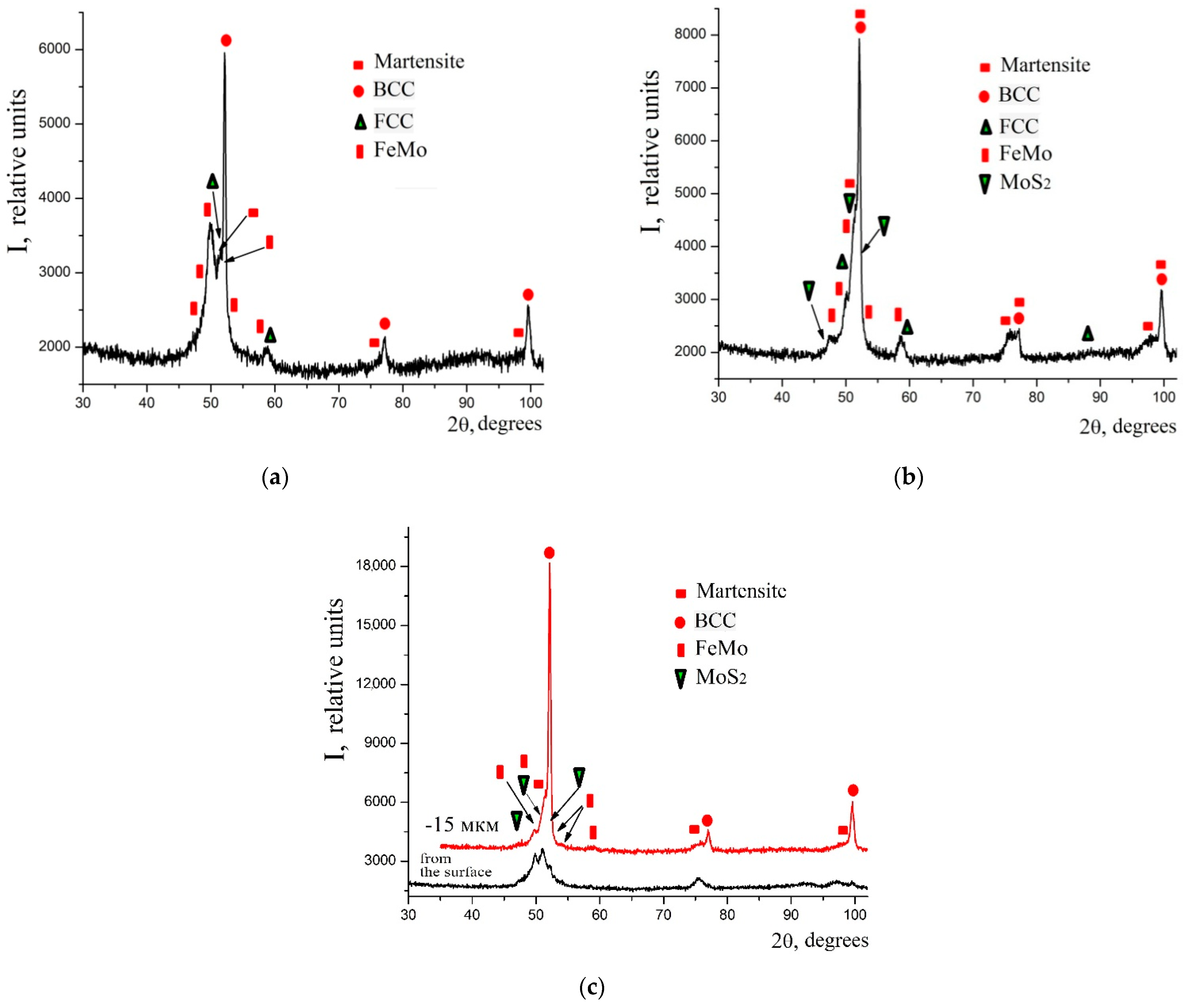
  • The X-ray diffraction analysis of the obtained coatings confirms the results of the energy dispersion analysis. At low discharge energies, the phase composition of the coatings on C40 steel is represented by BCC (body centered cubic) solid solution with a lattice period close to ferrite, martensite, FCC (face centered cubic) solid solution, and FeMointermetallide (σ-phase). When replacing the substrate made of C40 steel with the substrate made of C22 steel, the sulfomolybdenum coating reveals a smaller amount of the FCC phase that is residual austenite, at the same discharge energy. Molybdenum disulfide is even formed at the discharge energy Wp = 0.55 J (3.77%); and at Wp = 3.4 J, about 8% thereof is found on the surface, and about 5% thereof is found at a depth down to 15 μm.

Author Contributions

Conceptualization: O.P.G., V.B.T., and B.A.; methodology: O.P.G., B.A., and V.B.T.; software: O.M.M., P.K., and N.V.T.; validation: O.M.M., P.K., and N.V.T.; formal analysis: O.P.G. and V.B.T.; investigation: O.P.G., B.A., V.B.T., O.M.M., P.K., and N.V.T.; resources: O.M.M., P.K., and N.V.T.; data curation: O.P.G., V.B.T., O.M.M., and P.K.; writing—original draft preparation: O.P.G. and V.B.T.; writing—review and editing: P.K., N.V.T., and O.M.M.; visualization: O.M.M., P.K., and N.V.T.; supervision: B.A.; project administration: O.P.G.; funding acquisition: B.A. and P.K. All authors have read and agreed to the published version of the manuscript.

Funding

This research received no external funding.

Institutional Review Board Statement

Not applicable.

Informed Consent Statement

Not applicable.

Data Availability Statement

Conflicts of Interest

The authors declare no conflict of interest.

References

  1. Budnik, O.A.; Sviderskii, V.A.; Budnik, A.F.; Berladir, K.V.; Rudenko, P.V. Composite material for chemical and petrochemical equipment friction assemblies. Chem. Pet. Eng. 2016, 52, 63–68. [Google Scholar] [CrossRef]
  2. Pavlenko, I.V.; Simonovskiy, V.I.; Demianenko, M.M. Dynamic analysis of centrifugal machines rotors supported on ball bearings by combined application of 3D and beam finite element models. IOP Conf. Ser. Mater. Sci. Eng. 2017, 233, 012053. [Google Scholar] [CrossRef] [Green Version]
  3. Sviridenok, A.I.; Myshkin, N.K.; Kovaleva, I.N. Latest Developments in Tribology in the Journal of Friction and Wear. J. Frict. Wear 2015, 36, 449–453. [Google Scholar] [CrossRef]
  4. Jeon, C.H.; Jeong, Y.H.; Seo, J.J.; Tien, H.N.; Hong, S.T.; Yum, Y.J.; Hur, S.H.; Lee, K.J. Material Properties of Graphene/Aluminum Metal Matrix Composites Fabricated by Friction Stir Processing. Int. J. Precis. Eng. Manuf. 2014, 15, 1235–1239. [Google Scholar] [CrossRef]
  5. Roik, T.A.; Gavrish, A.P.; Kirichok, P.A.; Vitsyuk, Y.Y. Effect of Secondary Structures on the Functional Properties of High Speed Sintered Bearings for Printing Machines. Powder Metall. Met. Ceram. 2015, 54, 119–127. [Google Scholar] [CrossRef]
  6. Roik, T.A.; Gavrysh, O.A.; Vitsiuk, I.I.; Khmiliarchuk, O.I. New Copper-Based Composites for Heavy-Loaded Friction Units. Powder Metall. Met. Ceram. 2018, 56, 516–522. [Google Scholar] [CrossRef]
  7. Kostornov, A.G.; Fushchich, O.I. Sintered Antifriction Materials. Powder Metall. Met. Ceram. 2007, 46, 503–512. [Google Scholar] [CrossRef]
  8. Dachun, L.; Xiumin, C.; Dianjun, L.; Fei, W.; Xiaogang, L.; Bin, Y. Simulation of MoS2 crystal structure and the experimental study of thermal decomposition. J. Mol. Struct. 2010, 980, 66–71. [Google Scholar] [CrossRef]
  9. Pajovic, S.; Colas, G.; Saulot, A.; Renouf, M.; Filleter, T. Work of Adhesion Measurements of MoS2 Dry Lubricated 440C Stainless Steel Tribological Contacts. Adv. Eng. Mater. 2017, 19, 1700423. [Google Scholar] [CrossRef] [Green Version]
  10. He, Z.; Que, W. Molybdenum disulfide nanomaterials: Structures, properties, synthesis and recent progress on hydrogen evolution reaction. Appl. Mater. Today 2016, 3, 23–56. [Google Scholar] [CrossRef]
  11. Presting, H.; König, U. Future nanotechnology developments for automotive applications. Mater. Sci. Eng. C 2003, 23, 737–741. [Google Scholar] [CrossRef]
  12. Hsu, S.M. Molecular basis of lubrication. Tribol. Int. 2004, 37, 553–559. [Google Scholar]
  13. Afanasiev, P.; Xia, G.F.; Berhault, G.; Jouguet, B.; Lacroix, M. Surfactant Assisted Synthesis of Highly Dispersed Molybdenum Sulfide. Chem. Mater 1999, 11, 3216. [Google Scholar] [CrossRef]
  14. Lansdowne, A.R. Molybdenum Disulphide Lubrication; Elsevier: Amsterdam, The Netherlands, 1999. [Google Scholar]
  15. Bakunin, V.; Suslov, A.; Kuzmina, G.; Parenago, O.; Topchiev, A. Synthesis and Application of Inorganic Nanoparticles as Lubricant Components—A Review. J. Nanoparticle Res. 2004, 6, 273–284. [Google Scholar] [CrossRef]
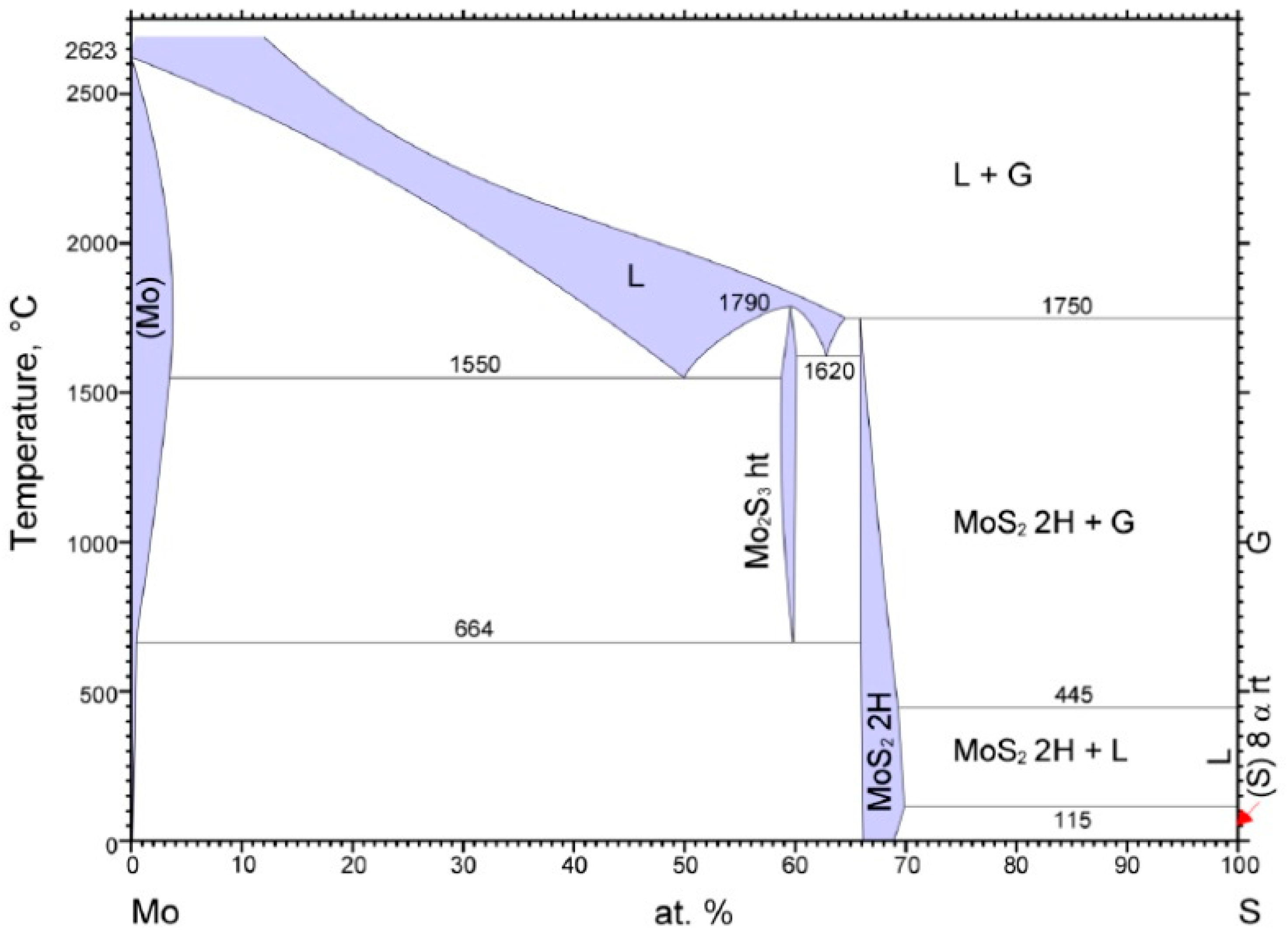
  16. Massalski, T.B. Binary Alloy. Phase Diagrams; ASM International: Novelty, OH, USA, 1990; p. 370. [Google Scholar]
  17. Gnezdilova, Y.P.; Serebrovsky, V.V. Strengthening by Sulfocyanization of Electrodeposited Iron-Molybdenum Coatings for the Restoration of Machine Parts; Publishing House of the Kursk State Agricultural Academy (KSAA): Kursk, Russian, 2008; p. 143. Available online: https://elibrary.ru/item.asp?id=19569072& (accessed on 8 June 2021)[in Russian].
  18. Martsynkovskyy, V.; Tarelnyk, V.; Konoplianchenko, Y.; Gaponova, O.; Dumanchuk, M. Technology support for protecting contacting surfaces of half-coupling—Shaft press joints against fretting wear. In Advances in Design, Simulation and Manufacturing II. DSMIE 2019. Lecture Notes in Mechanical Engineering; Springer: Berlin/Heidelberg, Germany, 2020; pp. 216–225. [Google Scholar]
  19. Timofeev, S.S. Application of Antifriction Coatings Containing Molybdenum Disulphide; Collection of Scientific Works of the Ukrainian State University of Railway Transport (UkrSURT), 2015; pp. 207–210. Available online: http://193.105.7.137/handle/123456789/1174 (accessed on 8 June 2021). [in Russian].
  20. Smorygo, O.; Voronin, S.; Bertrand, P.; Smurov, I. Fabrication of Thick Molybdenum Disulphide Coatings by Thermal-Diffusion Synthesis. Tribol. Lett. 2004, 17, 723–726. [Google Scholar] [CrossRef]
  21. Kostyk, K.; Hatala, M.; Kostyk, V.; Ivanov, V.; Pavlenko, I.; Duplakova, D. Simulation of diffusion processes in chemical and thermal processing of machine parts. Processes 2021, 9, 698. [Google Scholar] [CrossRef]
  22. Tarelnyk, V.B.; Gaponova, O.P.; Konoplyanchenko, I.V.; Evtushenko, N.S.; Herasymenko, V.A. The Analysis of a Structural State of Surface Layer after Electroerosive Alloying. I. Features of Formation of Electroerosive Coatings on Steel 45. Metallofiz. NoveishieTekhnol. 2018, 40, 235–254, [in Russian]. [Google Scholar]
  23. Tarelnyk, V.B.; Gaponova, O.P.; Konoplyanchenko, I.V.; Yevtushenko, N.S.; Herasymenko, V.O. The Analysis of a Structural State of Surface Layer after Electroerosive Alloying. II. Features of Formation of Electroerosive Coatings on Special Steels and Alloys by Hard Wear-Resistant and Soft Antifriction Materials, [in Russian]. Metallofiz. NoveishieTekhnol. 2018, 40, 795–815. [Google Scholar] [CrossRef]
  24. Lešnjak, A.; Tušek, J. Processes and properties of deposits in electrospark deposition. Sci. Technol. Weld. Join. 2002, 7, 391–396. [Google Scholar] [CrossRef]
  25. Ablaev, A.A.; Ratnikov, A.S. Technology of Electrospark Cladding of the Surfaces of the Cylinder-Piston Group of Engines for Transport-Technological Machines [in Russian]. In Problems of Operation and Maintenance of Transport-Technological Machines. Materials of the International Scientific and Technical Conference; Zakharov, N.S., Ed.; The Tyumen Industrial University: Tyumen, Russia, 2009; pp. 12–15. Available online: https://elibrary.ru/item.asp?id=23510188 (accessed on 8 June 2021).
  26. Tarelnyk, V.; Konoplyanchenko, I.V.; Martsynkovskyy, V.; Dovzhyk, M.; Dumanchuk, M.; Goncharenko, M.; Antoszewski, B.; Gaponova, O. Investigation of Qualitative Parameters of Surface Layers Formed by Stepwise Carburizing and Sulfo-Carburizing of Steel Parts with the Use of Electroerosion Alloying Method. In Proceedings of the 8th IEEE International Conference on Nanomaterials: Applications and Properties, NAP 2018, Zatoka, Ukraine, 9–14 September 2018; p. 03TFNMC26. [Google Scholar] [CrossRef]
Figure 1. Phase diagram of Mo-S system.
Materials 14 06332 g001
Figure 2. Microstructures in the surface layer of steel C22 after sulfomolybdenizing by ESA method: (a) Wp = 0.13 J; (b) Wp = 0.55 J; (c) Wp = 3.4 J.
Materials 14 06332 g002
Figure 3. Distribution of microhardness in the surface layer of steel C22 after sulfomolybdenizing by ESA method. On graph: 1—Wp = 0.13 J; 2—Wp = 0.55 J; 3—Wp = 3.4 J.
Materials 14 06332 g003
Figure 4. Microstructures in the surface layer of steel C40 after sulfomolybdenizing by ESA method: (a) Wp = 0.13 J; (b) Wp = 0.55 J; (c) Wp = 3.4 J.
Materials 14 06332 g004
Figure 5. Distribution of microhardness in the surface layer of steel C40 after sulfomolybdenizing by ESA method. On graph: 1—Wp = 0.13 J; 2—Wp = 0.55 J; 3—Wp = 3.4 J.
Materials 14 06332 g005
Figure 6. The results of electron microscopic studies of steel C40 sulfomolybdenum coatings obtained by ESA method: (a) Wp = 0.13 J; (b) Wp = 0.55 J; (c) Wp = 3.4 J.
Materials 14 06332 g006
Figure 7. Maps of the distribution of chemical elements in the coating after sulfomolybdenizing steel C40 by ESA method at different discharge energies: (a) Wp = 0.13 J; (b) Wp = 0.55 J; (c) Wp = 3.4 J.
Materials 14 06332 g007aMaterials 14 06332 g007b
Figure 8. Distribution of elements (sulfur, molybdenum, and iron) in sulfomolybdenum coatings obtained by ESA method on steel C40: (a) Wp = 0.13 J; (b) Wp = 0.55 J; (c) Wp = 3.4 J.
Materials 14 06332 g008aMaterials 14 06332 g008b
Figure 9. Diffractograms of sulfomolybdenum coatings obtained by ESA method on steel C40: (a) Wp = 0.13 J; (b) Wp = 3.4 J.
Materials 14 06332 g009
Figure 10. Diffractograms of sulfomolybdenum coatings obtained by ESA method on steel C22: (a) Wp = 0.13 J; (b) Wp = 0.55 J; (c) Wp = 3.4 J.
Materials 14 06332 g010
Table 1. Dependence of ESA productivity on discharge energy.
Discharge Energy Wp, JProductivity, cm2/min
0.130.8 ÷ 1.0
0.551.0 ÷ 1.3
1.31.3 ÷ 1.5
2.61.5 ÷ 2.0
3.42.0 ÷ 2.5
6.82.5 ÷ 3.0
Table 2. Qualitative parameters of sulfomolybdenum coatings obtained by ESA method (S, %—layer continuity).
Discharge Energy, JRoughness, μmLayer of Reduced MicrohardnessStrengthened Layer
RaRzRmaxHµ, MPah, μmS, %Hµ, MPah, μmS, %
Steel C22
0.130.62.16.11112 ± 20020 ± 545 ± 55147 ± 20020 ± 565 ± 5
0.551.93.314.21368 ± 20030 ± 565 ± 57150 ± 20030 ± 575 ± 5
3.405.514.738.51666 ± 20040 ± 575 ± 510596 ± 20050 ± 590 ± 5
Steel C40
0.130.82.36.51320 ± 20010 ± 550 ± 55474 ± 20025 ± 575 ± 5
0.552.03.514.71670 ± 20020 ± 570 ± 57832 ± 20040 ± 590 ± 5
3.405.714.938.72040 ± 20030 ± 580 ± 510731 ± 20070 ± 595 ± 5
Table 3. Parameters for crystal lattices of phases and quantitative phase analysis of the sulfomolybdenum coatings on C40 steel.
Discharge Energy, JPhaseLattice Period, a, nmPhase Content, % (mass.)
0.55BCC solid solution2.872023.90
FCC solid solution3.645025.38
Martensitea = 2.8740
c = 2.9200
10.98
FeMo (σ-phase)a = 9.1280
c = 4.8130
39.74
At a depth down to 15 µm
3.4BCC solid solution2.872046.36
FCC solid solution3.64506.10
Martensitea = 2.8640
c = 2.9200
30.14
FeMo (σ-phase)a = 9.1280
c = 4.8130
12.53
MoS2a = 3.1212
c = 12.2410
4.87
Table 4. Parameters for crystal lattices of phases and quantitative phase analysis of the sulfomolybdenum coatings on C22 steel.
Discharge Energy, JPhaseLattice Period, a, nmPhase Content, % (mass.)
0.13BCC solid solution2.872039.43
FCC solid solution3.645016.15
Martensitea = 2.8640
c = 2.9200
18.22
0.55BCC solid solution2.872034.92
FCC solid solution3.645013.72
Martensitea = 2.8640
c = 2.9200
30.46
FeMo (σ-phase)a = 9.1280
c = 4.8130
17.14
MoS2a = 3.1212
c = 12.2410
3.77
At a depth down to 15 µm
3.4BCC solid solution2.880059.86
Martensitea = 2.8640
c = 2.9200
25.46
FeMo (σ-phase)a = 9.1280
c = 4.8130
9.56
MoS2a = 3.1212
c = 12.2410
5.12
Publisher’s Note: MDPI stays neutral with regard to jurisdictional claims in published maps and institutional affiliations.

