
Process Chain Development for the Fabrication of Three-Dimensional Braided Oxide Ceramic Matrix Composites

 , ,
, ,
Abstract
:1. Introduction
2. Materials and Methods
3. Results and Discussion
3.1. Results and Discussion—Textile Development
3.1.1. Winding Process Design
3.1.2. Bobbin Development
3.1.3. Fiber Damage Influences on the Bobbin
3.1.4. Concept
3.1.5. Component Design
3.1.6. Braiding Ring
3.2. Results and Discussion—Fiber Composite Ceramics
4. Conclusions
Author Contributions
Funding
Institutional Review Board Statement
Informed Consent Statement
Acknowledgments
Conflicts of Interest
References
- Bundesverband der Deutschen Luftverkehrswirtschaft e. V. (Hrsg.). Energieeffizienz und Klimaschutz Report 2017; Bundesverband der Deutschen Luftverkehrswirtschaft: Berlin, Germany, 2017; Available online: https://www.bdl.aero/wp-content/uploads/2018/08/klimaschutz-report_2017_v5.pdf (accessed on 10 December 2020).
- Gardiner, G. Aeroengine Composites, Part 2: CFRPs Expand. Composite World. 31 August 2015. Available online: https://www.compositesworld.com/articles/aeroengine-composites-part-2-cfrps-expand (accessed on 10 December 2015).
- Hegmann, G. Mit Diesem Triebwerk Startet die Ära Großer E-Flugzeuge. Die Welt. 28 November 2017. Available online: https://www.welt.de/wirtschaft/article171058947/Mit-diesem-Triebwerk-startet-die-Aera-grosser-E-Flugzeuge.html (accessed on 20 December 2017).
- Mouritz, A.P. Introduction to Aerospace Materials; Woodhead Publishing: Sawston, UK, 2012. [Google Scholar]
- Vicari, A.; Schiavo, A. Innovations Moving Structural Ceramics into the Mainstream. Machine Design. 30 July 2015. Available online: https://www.machinedesign.com/materials/article/21834348/innovations-moving-structural-ceramics-into-the-mainstream (accessed on 10 August 2021).
- Wamser, T. Herstellung von Oxidkeramischen Verbundwerkstoffen Mittels Freeze-Casting. Ph.D. Thesis, Cuvillier Verlag, Göttingen, Germany, 2016. [Google Scholar]
- Rüdinger, A.; Pritzkow, W. Die Entwicklung oxidkeramischer Faserverbundwerkstoffe am Fraunhofer ISC/Zentrum HTL in Zusammenarbeit mit WEC Pritzkow Spezialkeramik. Keram. Z. 2013, 65, 166–169. [Google Scholar]
- Levi, C.G.; Zok, F.W.; Yang, J.Y.; Mattoni, M.; Löfvander, J.P.A. Microstructural Design of Stable Porous Matrices for All-Oxide Ceramic Composites. Z. Metallkunde 1999, 90, 1037–1047. [Google Scholar]
- Simon, R.A.; Danzer, R. Oxide Fiber Composites with Promising Properties for High-Temperature Structural Applications. Adv. Eng. Mater. 2006, 8, 129–1134. [Google Scholar] [CrossRef]
- Zok, F.W. Developments in Oxide Fiber Composites. J. Am. Ceram. Soc. 2006, 89, 3309–3324. [Google Scholar] [CrossRef]
- Carey, J.P. Advanced testing of braided composite materials. In Handbook of Advances in Braided Composite Materials—Theory, Production, Testing and Application, 1st ed.; Melenka, G.W., Hunt, A.J., Pastore, C.M., Ko, F.K., Carey, J.P., Eds.; Woodhead Publishing: Sawston, UK, 2017; pp. 155–197. [Google Scholar]
- Kiser, J.D.; Grady, J.W.; Smith, C.E.; Sullivan, R.M.; Wiesner, V.L. Overview of ceramic matrix composite. In Proceedings of the Ceramics Expo 2016, Cleveland, OH, USA, 26–28 April 2016; NASA Glenn Research Center: Cleveland, OH, USA, 2017. [Google Scholar]
- Stegschuster, G.; Pingkarawat, K.; Wendland, B.; Mouritz, A.P. Experimental determination of the mode I delamination fracture and fatigue properties of thin 3D woven composites. Compos. Part A Appl. Sci. Manuf. 2016, 84, 308–315. [Google Scholar] [CrossRef]
- Fishpool, D.T.; Rezai, A.; Baker, D.; Ogin, S.L.; Smith, P.A. Interlaminare Zähigkeitscharakterisierung von 3D-gewebten Kohlefaserverbundwerkstoffen. Plast Rubb. Compos. 2013, 42, 108–114. [Google Scholar] [CrossRef] [Green Version]
- Pritzkow, W.E. Keramikblech—Dünnwandige Keramik ersetzt Metallblechteile. Keramische Z. 2003, 55, 208–210. [Google Scholar]
- Pritzkow, W.E.C.; Almeida, R.S.M.; Mateus, L.B.; Tushtev, K.; Rezwan, K. All-oxide ceramic matrix composites (OCMC) based on low cost 3M Nextel™ 610 fabrics. J. Eur. Ceramic Soc. 2021, 41, 3177–3187. [Google Scholar] [CrossRef]
- 3M Company Corp. (Hrsg.). 3M™ Nextel™ Ceramic Fibers and Textiles: Technical Reference Guide; 3M Advanced Materials Division, 3M Center: Saint Paul, MN, USA, 2019. [Google Scholar]
- Göring, J.; Hackemann, S.; Schneider, H. Oxid/Oxid-Verbundwerkstoffe: Herstellung, Eigenschaften und Anwendungen. In Keramische Verbundwerkstoffe; Wiley: Hoboken, NJ, USA, 2002; pp. 122–148. [Google Scholar]
- Keller, K.A.; Jefferson, G.; Kerans, R.J. Handbook of Ceramic Composites; Kluwer Academic Publisher: Norwell, MA, USA, 2006; pp. 377–422. [Google Scholar]
- Beaber, A.; Ross, A.; Simpson, M.; Atmur, S.; Simpson, W.; Szweda, A. 3M™ Nextel™ Spread Tow: Enabling Automated Processing Methods and Unique Composite Constructions; 3M Company, COI Ceramics: Saint Paul, MN, USA, 23 January 2018. [Google Scholar]
- Puchas, G.; Möckel, S.; Krenkel, W. Novel prepreg manufacturing process for oxide fiber composites. J. Eur. Ceram. 2020, 40, 5930–5941. [Google Scholar] [CrossRef]
- Puchas, G.; Held, A.; Krenkel, W. Near-net shape manufacture process for oxide fiber composites (OFC). Mater. Today-Proc. 2019, 16, 49–58. [Google Scholar] [CrossRef]
- Engels, H. Handbuch der Schmaltextilien—Flechttechnologie Teil 2: Maschinen und Verfahren zur Erzeugung von Flechtprodukten MIT Spezielle physikalische und Chemische Anforderungen, 1st ed.; Springer: Berlin/Heidelberg, Germany, 1994. [Google Scholar]
- Rosiepen, C. Methode zur Anpassung Textiler Tribosysteme am Beispiel der Verarbeitung von Hochmodulfasern. Ph.D. Thesis, Technische Hochschule, Aachen, Germany, 2016. [Google Scholar]
- Rosenbaum, J.U. Flechten: Rationelle Fertigung faserverstärkter Kunststoffbauteile. Ph.D. Thesis, Technische Hochschule, Aachen, Germany, 1990. [Google Scholar]
- Red, C. Composites in Commercial Aircraft Engines, 2014–2023. Composite World. 6 January 2015. Available online: https://www.compositesworld.com/articles/composites-in-commercial-aircraft-engines-2014-2023 (accessed on 14 December 2015).
- Büsgen, W.A. Neue Verfahren zur Herstellung von dreidimensionalen Textilien für den Einsatz in Faserverbundwerkstoffen. Ph.D. Dissertation, Techniche Hochschule, Aachen, Germany, 1993. [Google Scholar]
- Mierzwa, A.; Ebel, C.; Harbers, T.; Drechsler, K. Investigation on Creation of Fibrous Rings and their Influence on the Braided Preform Quality. In Proceedings of the 17th European Conference on Composite Materials: ECCM17 Conference Proceedings, München, Germany, 26–30 June 2016. [Google Scholar]
- Ebel, C. Hochgeschwindigkeitsumflechten für die Fertigung von Faserverbundbauteilen. Ph.D. Dissertation, Technische Universität München, München, Germany, 2017. [Google Scholar]
- Mierzwa, A. Zur Entstehung und Auswirkung von Garnlücken in Carbonbiaxialgeflechten. Ph.D. Dissertation, Technische Universität München, München, Germany, 2019. [Google Scholar]
- Kan, Y.; Liu, Z. Three-Dimensional Braiding Yarn Carrier. CN Patent 104805591 A1, 24 August 2016. [Google Scholar]
- El-Shiekh, A.; Hammad, M.; Li, W. Yarn Carrier Apparatus for Braiding Machines and the Like. U.S. Patent 5,156,079, 20 October 1992. [Google Scholar]
- Hirukawa, M.; Uchida, Y.; Yamamoto, T. Production Apparatus for Pipe. JP Patent 2765511 B2, 18 June 1998. [Google Scholar]
- Baeumer, T. Flechtklöppel; Flechtmaschine und Verfahren zum Abzug eines Faserfadens von der Spule eines Flechtklöppels. DE Patent 10 2008 038 281 A1, 24 February 2010. [Google Scholar]
- Braeuner, M.O.; Gulden, D. Klöppel für eine Flechtmaschine, Flechtmaschine und Verfahren zum Erzeugen einer Zugspannung in Flechtmaterial beim Flechten. DE Patent 10 2019 101 619, 23 July 2020. [Google Scholar]
- Ashton, C.H.; Brown, R.T. Fiber Spool Apparatus. EP Patent 0 402 526 A2, 6 June 1989. [Google Scholar]
- Baek, S.S.; Choi, J.H.; Choi, J.S.; Lee, J.Y.; Song, B.H.; Song, J.K. The Yarn Feeder with Automatic Tension Control for Braid Machine. KR Patent 101456146 B1, 14 August 2014. [Google Scholar]
- Moyer, J.D. Flechtklöppel. EP Patent 0 211 581 A2, 12 July 1985. [Google Scholar]
- Schneider, M. Konstruktion von Dreidimensional Geflochtenen Verstärkungstextilien für Faserverbundwerkstoffe. Ph.D. Thesis, Technische Universität, Aachen, Germany, 2000. [Google Scholar]
- Lünenschloß, J.; Gilhaus, K. Die Ermittlung des Reibungskoeffizienten; Melliand Textilberichte: Frankfurt, Germany, 1979; pp. 107–109. [Google Scholar]
- Guglielmi, P.O.; Blaese, D.; Hablitzel, M.P.; Nunes, G.F.; Lauth, V.R.; Hotza, D.; Al-Qureshi, H.A.; Janssen, R. Microstructure and flexural properties of multilayered fiber reinforced oxide composites fabricated by a novel lamination route. Ceram. Int. 2015, 41, 7836–7846. [Google Scholar] [CrossRef]


| Fiber-to-Fiber Friction as a Result of a Non-Tangential Pull-Off from the Coil | ||
 Coulomb formula | Solutions and partial solutions:
| |
| (2) | ||
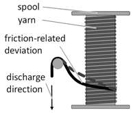
| Yarn Damage Due to Friction as a Result of Deflection at Yarn Guiding Elements | ||
| Rolling resistance force | Solutions and partial solutions:
| |
| (3) | ||
| Euler–Eytelwein formula | ||
| (4) | ||
| Yarn Damage Due to Mass Inertia, Bearing and Gear-Related Frictional Resistance | ||
| Dynamic force balance | Solutions and partial solutions:
| |
| (5) | ||
| Filament Ring Formation During Unwinding | ||
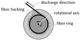 | Solutions and partial solutions:
| |
| Designation | Lower Value (−) | / | Upper Value (+) | Maximum Thread Tension Force | Minimum Thread Tension Force | Settling Length | |
|---|---|---|---|---|---|---|---|
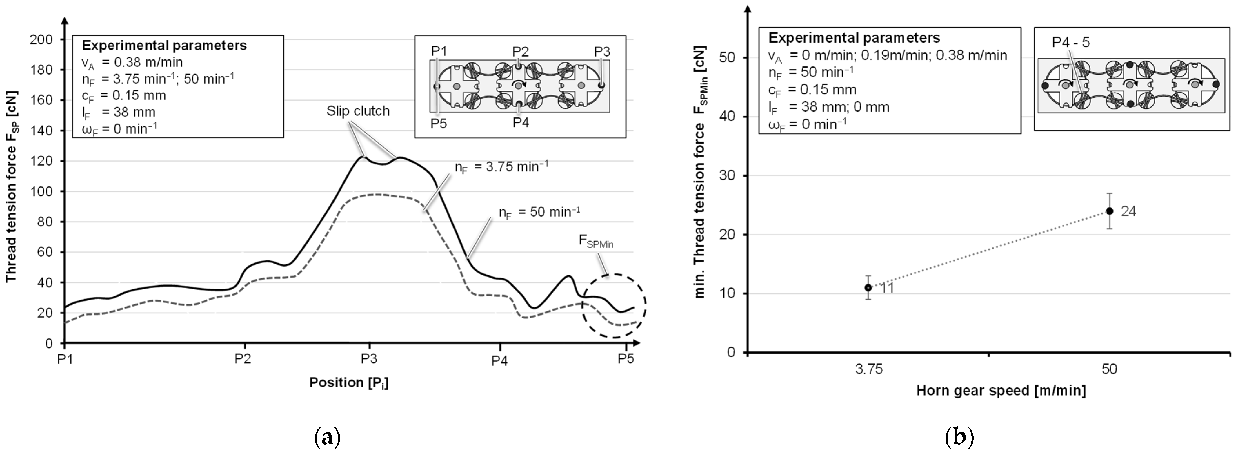
| Pull-off speed | vA | 0 m/min | → | 0.38 m/min | + | + | / |
| Horn gear speed | nF | 3.75 min−1 | → | 50 min−1 | + | + | + |
| Spring thickness | cF | 0.12 mm | → | 0.15 mm | + | + | + |
| Yarn eye deflection | lF | 0 mm | → | 38 mm | - | / | / |
| Rotatability | ωF | =0 min−1 | → | ≠0 min−1 | - | / | / |
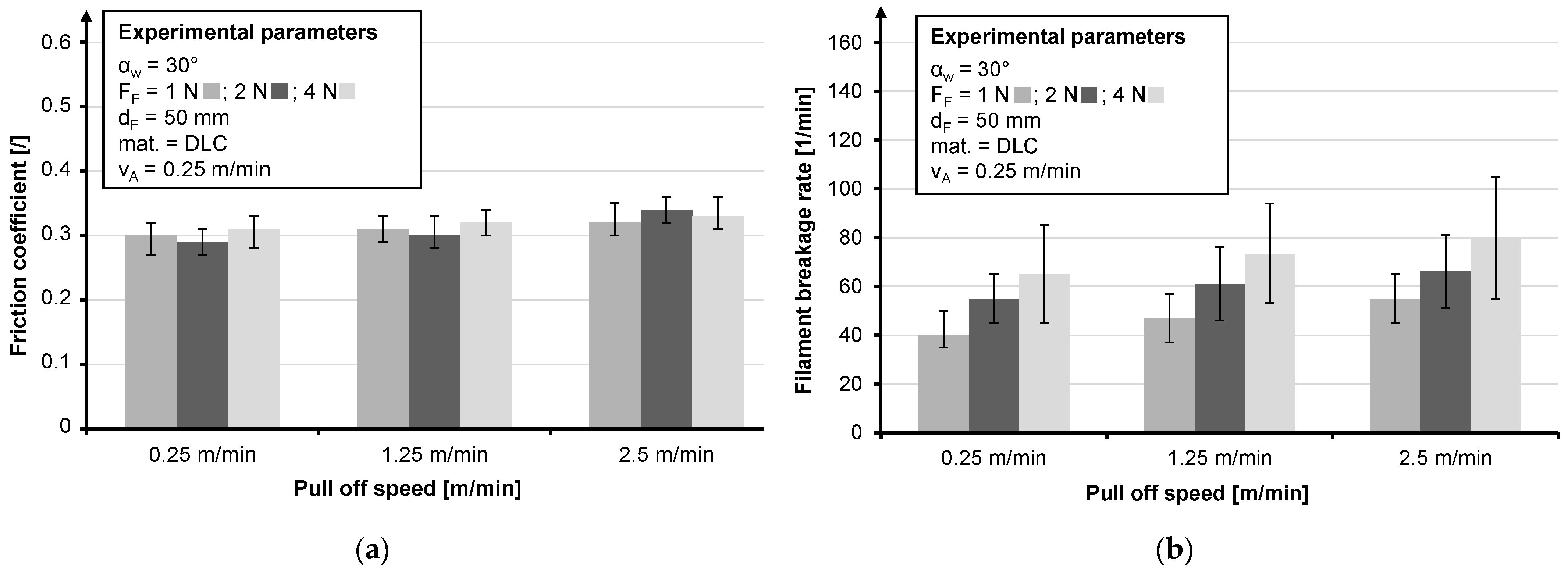
| Friction Body Material (mat.) | Friction Body Diameter (dF) | Fiber Force (FF) | Pull-Off Speed (vA) |
|---|---|---|---|
| Polished stainless steel (VA) | 10 mm | 1 N | 0.25 m/min |
| VA with diamond-like carbon (DLC) | 30 mm | 2 N | 1.25 m/min |
| VA with titanium carbonitride (TiCN) | 50 mm | 4 N | 2.5 m/min |
| VA with Topocrom Nr. 131 (TOP) | 70 mm |
| Spring Strength (g/ N) | 100 g/1 N | 200 g/2 N | ||||
|---|---|---|---|---|---|---|
| Braiding Angle (°) | 30° | 45° | 60° | 30° | 45° | 60° |
| Vibrator off, ILSS (MPa) | 14.8 ± 1.0 MPa | 13.0 ± 1.1 MPa | 11.8 ± 1.0 MPa | 13.8 ± 1.1 MPa | 12.0 ± 2.2 MPa | 10.7 ± 2.7 MPa |
| Vibrator on, ILSS (MPa) | 14.1 ± 1.1 MPa | 12.1 ± 1.7 MPa | 11.1 ± 1.6 MPa | 14.8 ± 0.3 MPa | 12.1 ± 0.9 MPa | 11.1 ± 1.1 MPa |
| Test Series | ILSS (MPa) | Flexural Strength (MPa) | Fiber Volume Content (%) | Z-Fiber Content (%) | Braiding Angle |
|---|---|---|---|---|---|
| Sample 1 | 21.7 ± 4.8 | 354 ± 48 | 26.0 | 7.2 | 30° |
| Sample 2 | 23.7 ± 3.3 | 358 ± 53 | 26.1 | 10.6 | 30° |
| Sample 3 | 24.3 ± 1.7 | 374 ± 64 | 27.2 | 13.1 | 30° |
| Textile Type | Fiber Angle (°) | Fiber Volume Content (%) | Flexural Strength (MPa) | ILSS (MPa) | Z-Fiber Content (%) |
|---|---|---|---|---|---|
| Two-dimensional woven fabric | 0/90° | 38.1% | 220 ± 19 MPa | 12.4 ± 2.4 MPa | 0% |
| Two-dimensional braid | 30° | 30.2% | 216 ± 47 MPa | 14.8 ± 1.0 MPa | 1.5% |
| Three-dimensional braid | 30° | 27.2% | 374 ± 64 MPa | 24.3 ± 1.7 MPa | 13.1% |
Publisher’s Note: MDPI stays neutral with regard to jurisdictional claims in published maps and institutional affiliations. |
© 2021 by the authors. Licensee MDPI, Basel, Switzerland. This article is an open access article distributed under the terms and conditions of the Creative Commons Attribution (CC BY) license (https://creativecommons.org/licenses/by/4.0/).
Share and Cite
Kolloch, M.; Puchas, G.; Grigat, N.; Vollbrecht, B.; Krenkel, W.; Gries, T. Process Chain Development for the Fabrication of Three-Dimensional Braided Oxide Ceramic Matrix Composites. Materials 2021, 14, 6338. https://doi.org/10.3390/ma14216338
Kolloch M, Puchas G, Grigat N, Vollbrecht B, Krenkel W, Gries T. Process Chain Development for the Fabrication of Three-Dimensional Braided Oxide Ceramic Matrix Composites. Materials. 2021; 14(21):6338. https://doi.org/10.3390/ma14216338
Chicago/Turabian StyleKolloch, Martin, Georg Puchas, Niels Grigat, Ben Vollbrecht, Walter Krenkel, and Thomas Gries. 2021. "Process Chain Development for the Fabrication of Three-Dimensional Braided Oxide Ceramic Matrix Composites" Materials 14, no. 21: 6338. https://doi.org/10.3390/ma14216338
APA StyleKolloch, M., Puchas, G., Grigat, N., Vollbrecht, B., Krenkel, W., & Gries, T. (2021). Process Chain Development for the Fabrication of Three-Dimensional Braided Oxide Ceramic Matrix Composites. Materials, 14(21), 6338. https://doi.org/10.3390/ma14216338