
Laboratory Tests of Concrete Beams Reinforced with Recycled Steel Fibres and Steel Bars


Abstract
:1. Introduction
2. Experimental Program
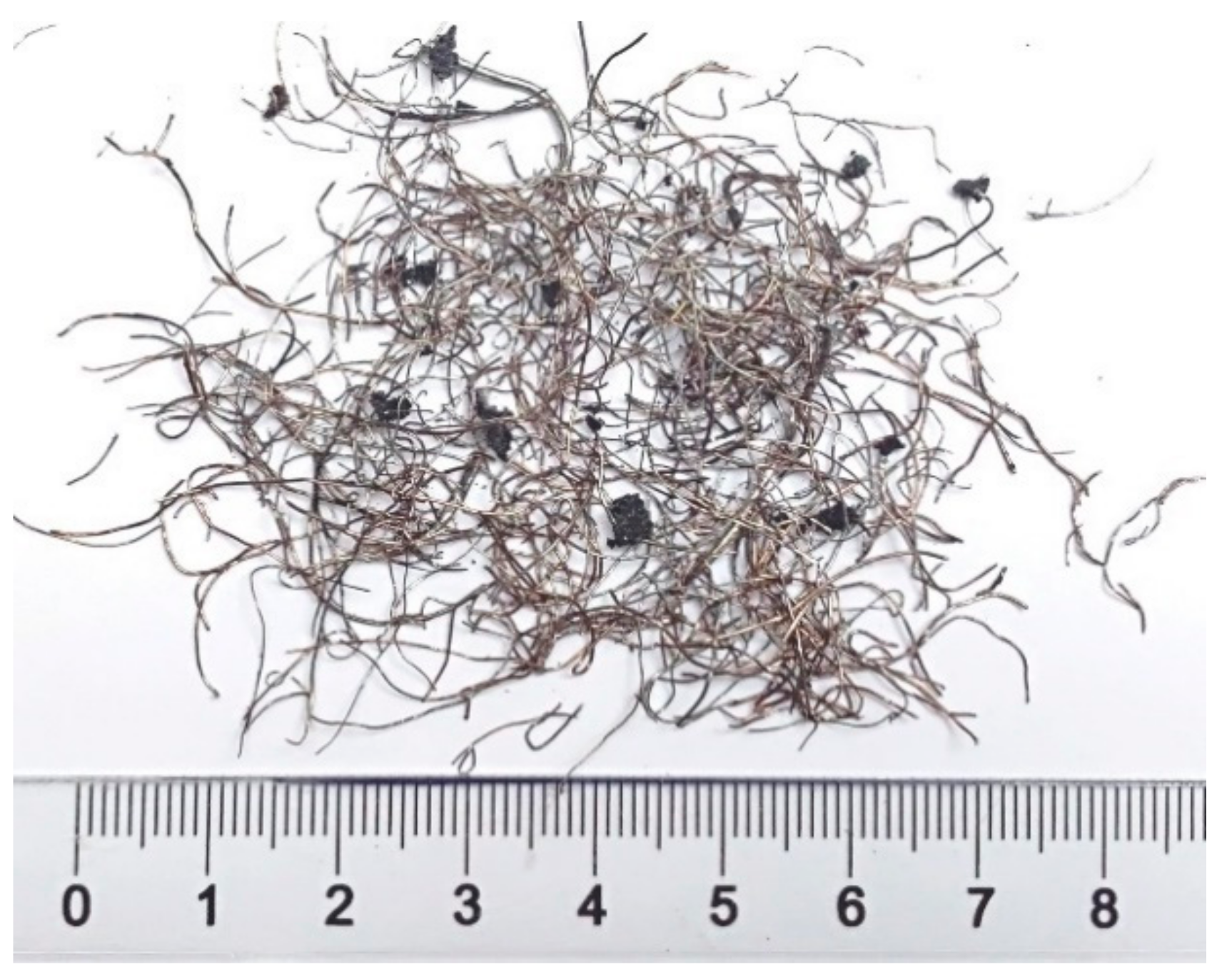
2.1. Materials
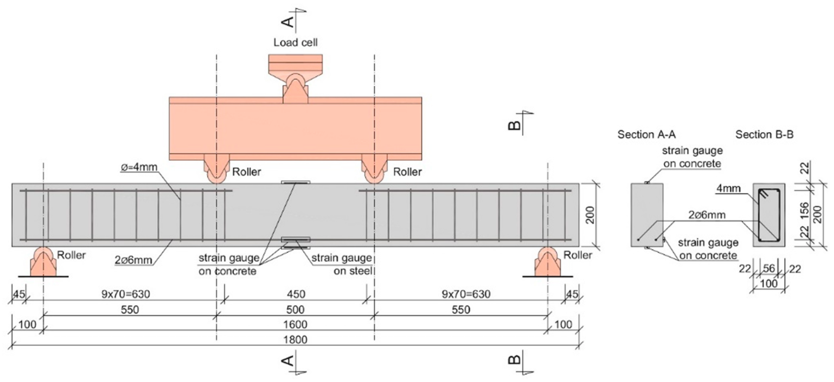
2.2. Specimens and Testing Methods
2.2.1. Compression and Flexural Tests
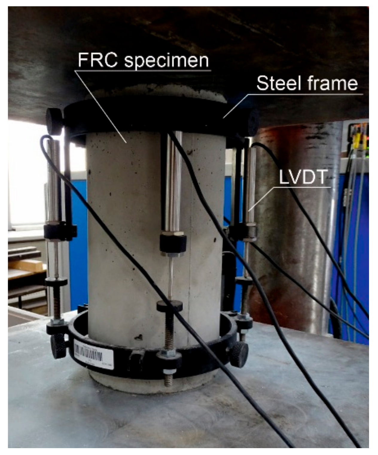
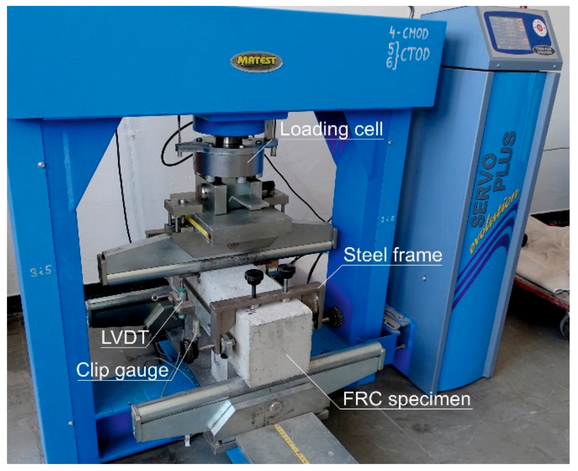
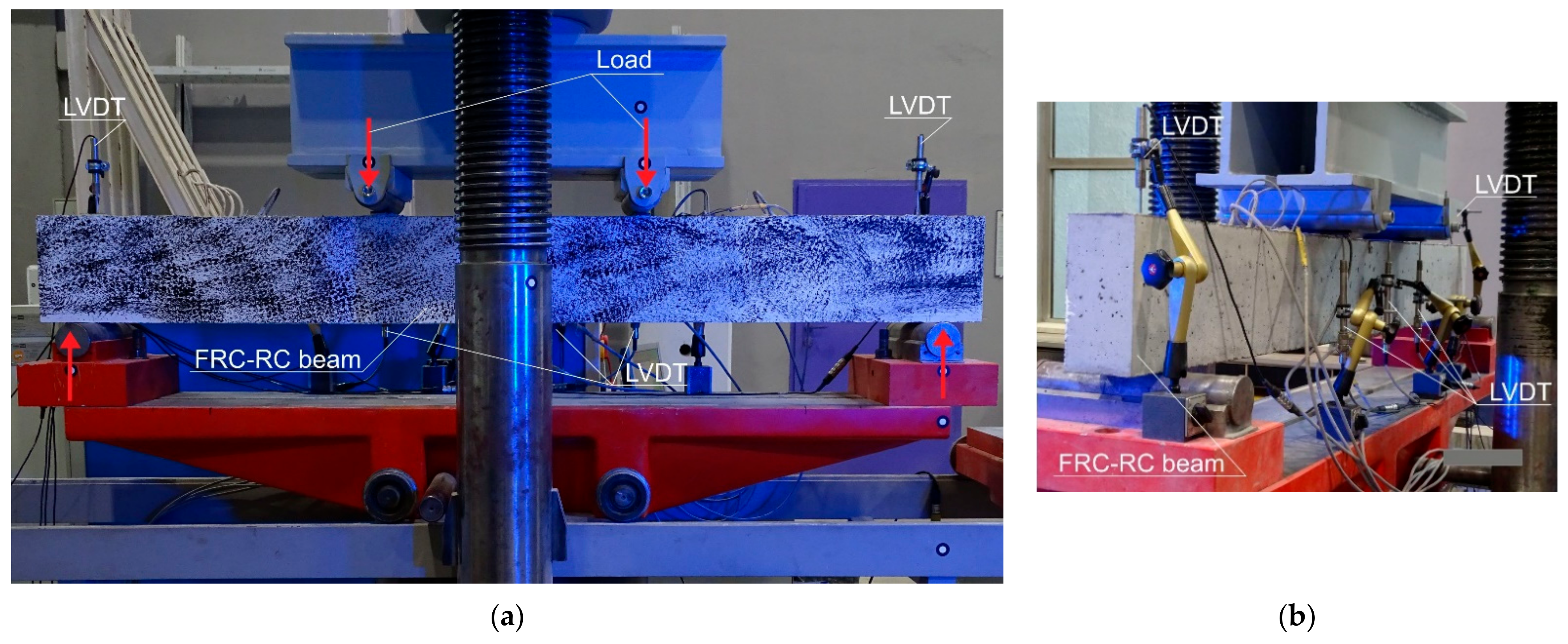
2.2.2. Structural Tests
3. Results of Empirical Investigation
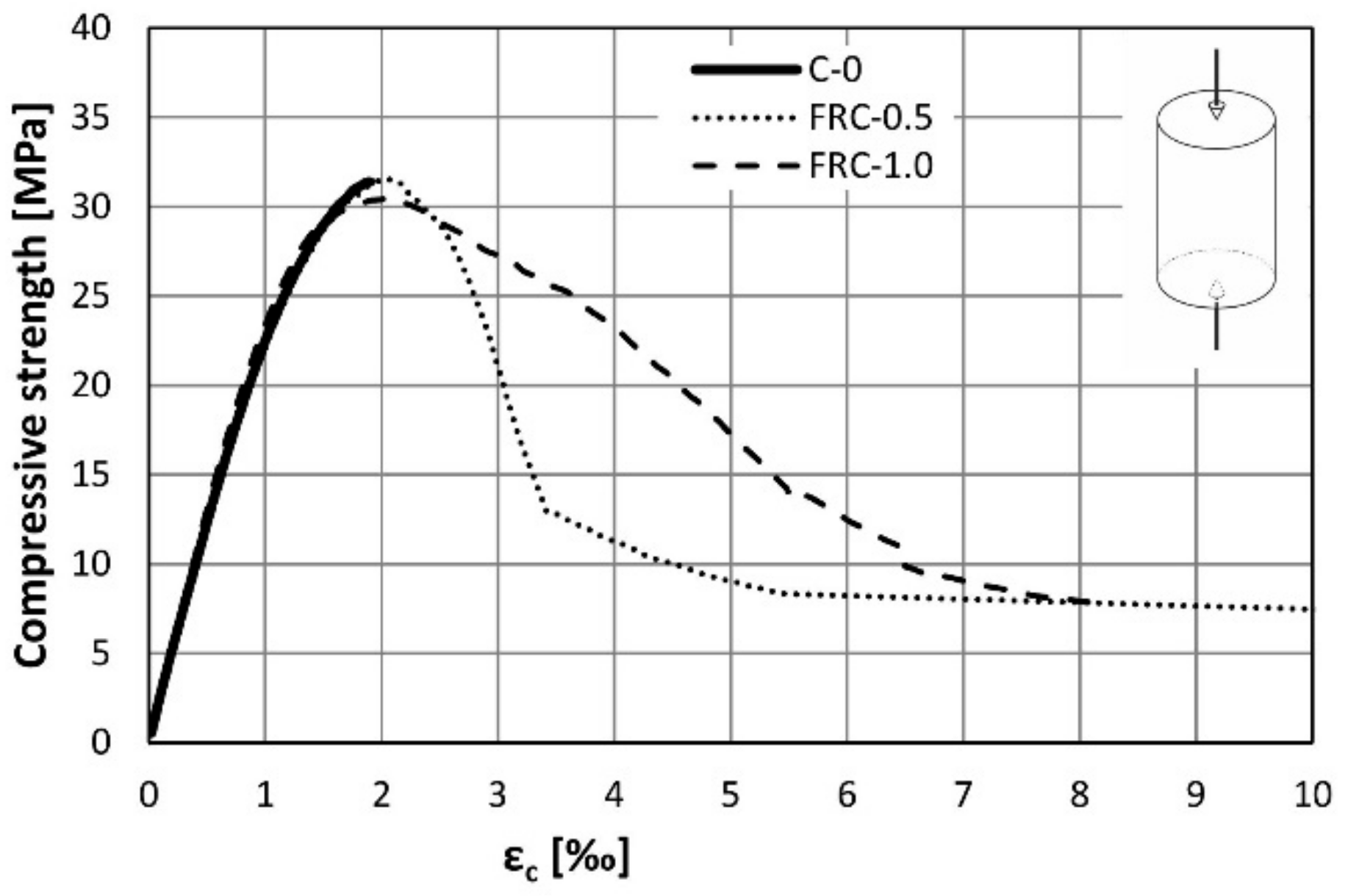
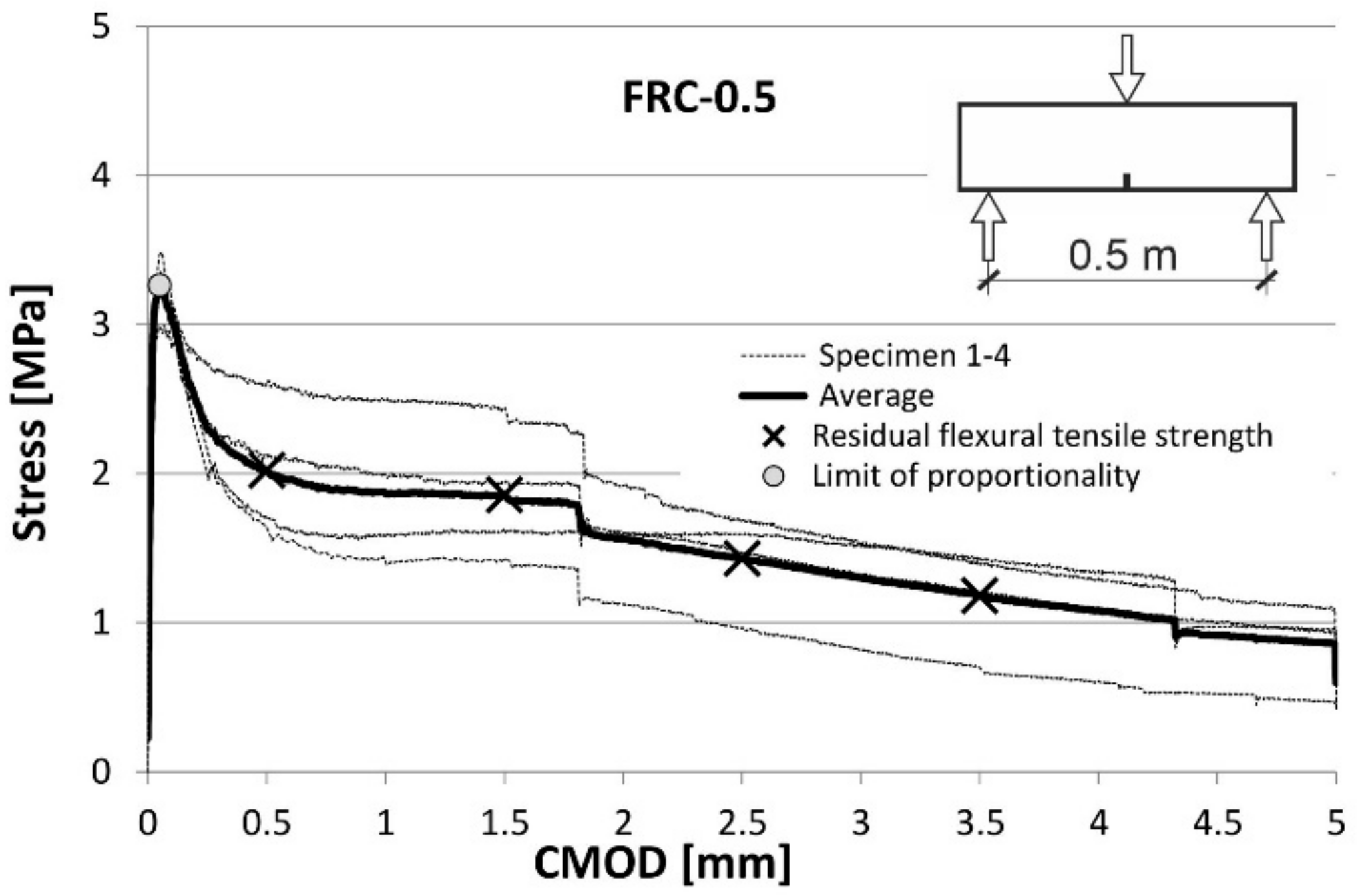
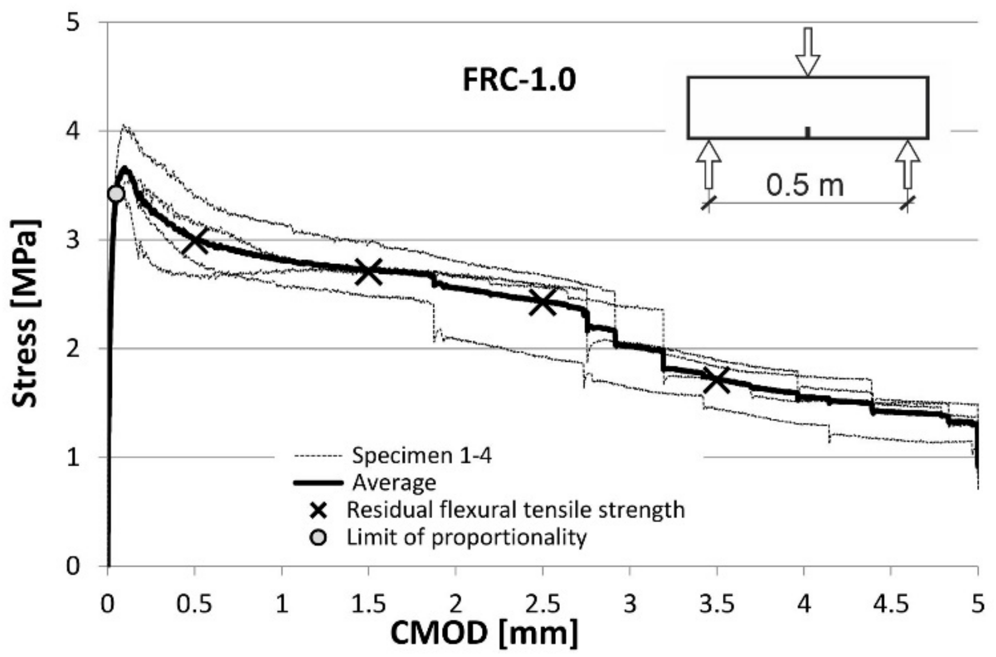
3.1. The Compression and Flexural Material Tests
3.2. The Full-Scale Beam Tests
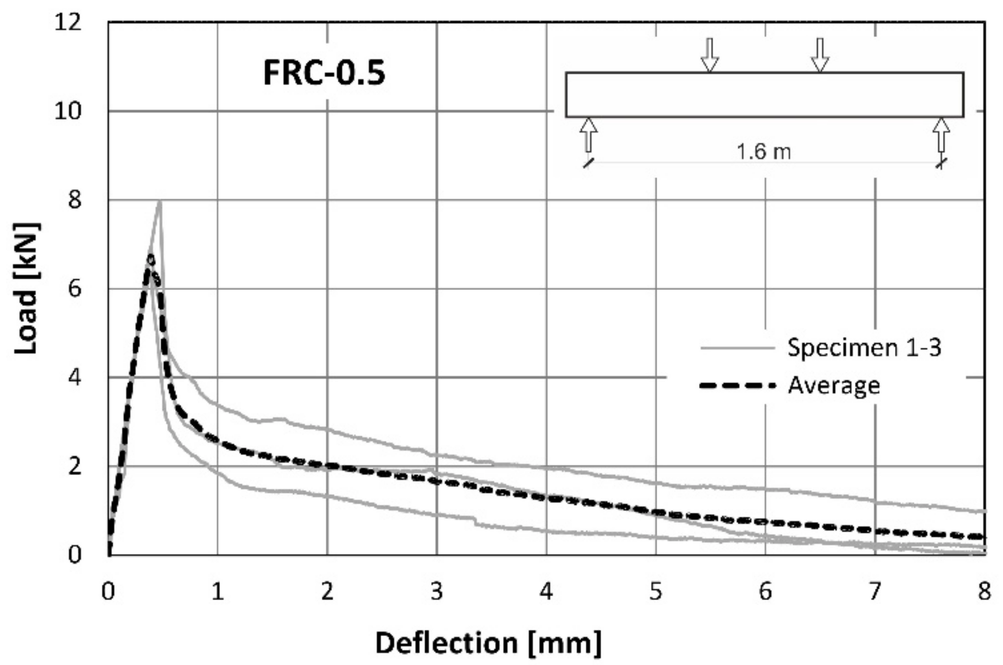
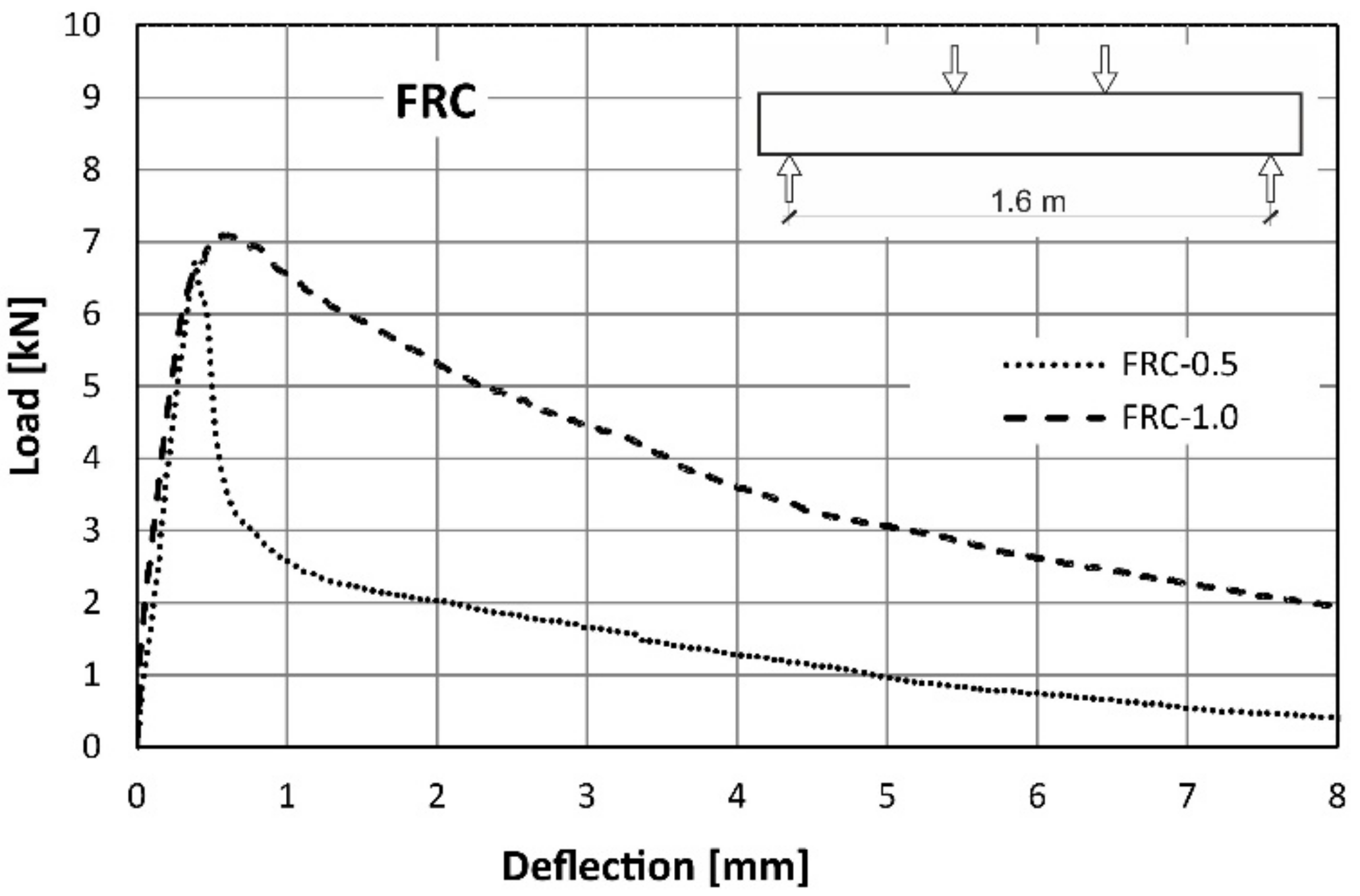
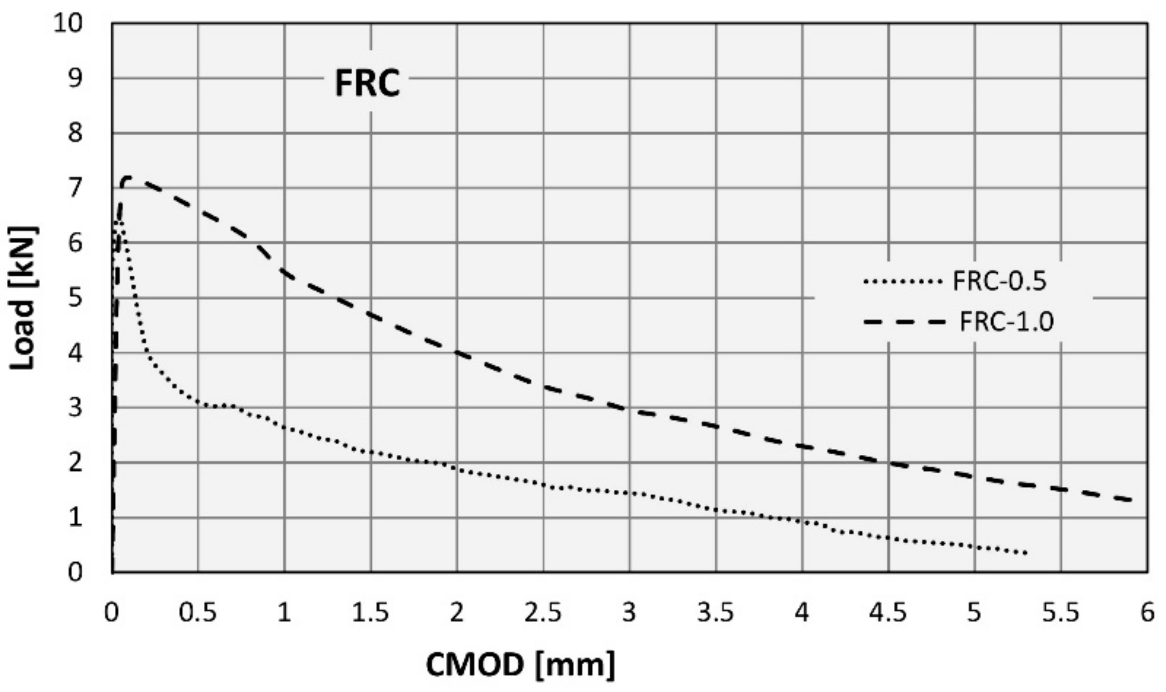
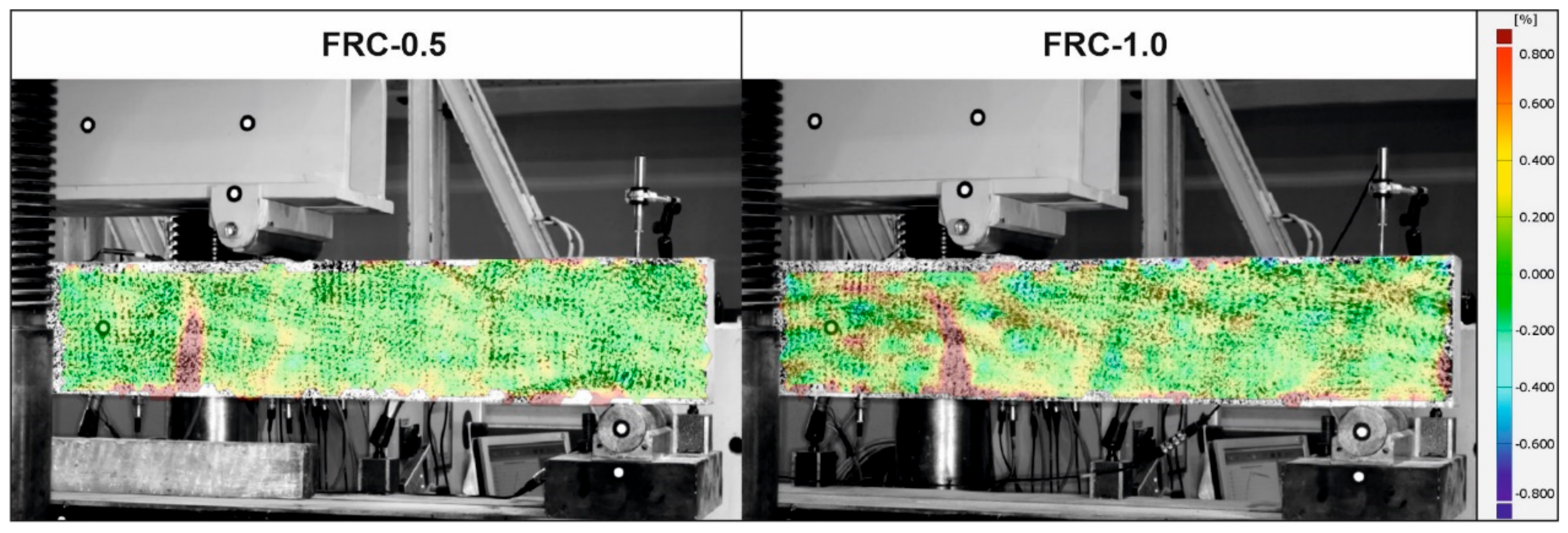
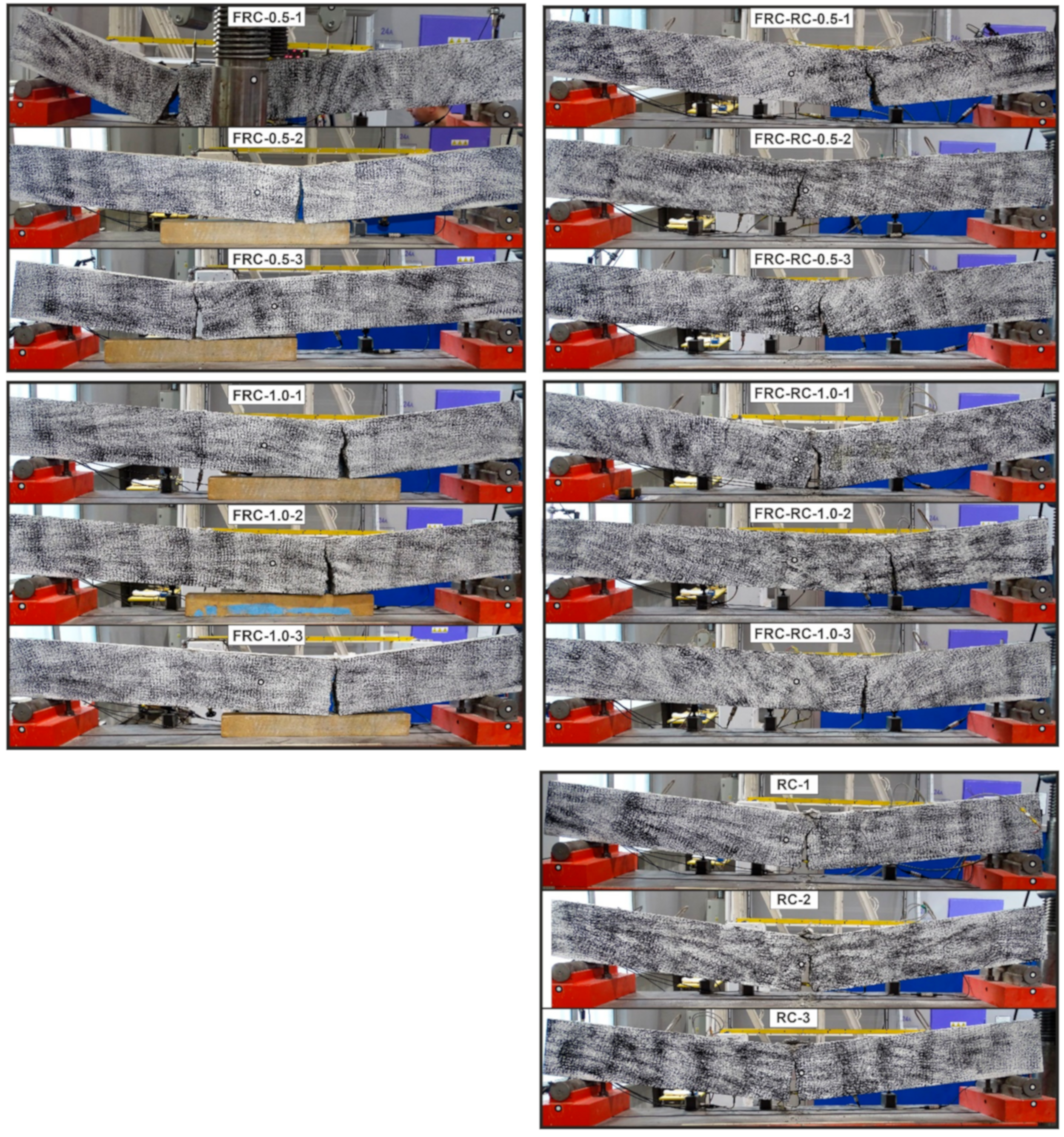
3.2.1. The Beams Reinforced Only with the RSF
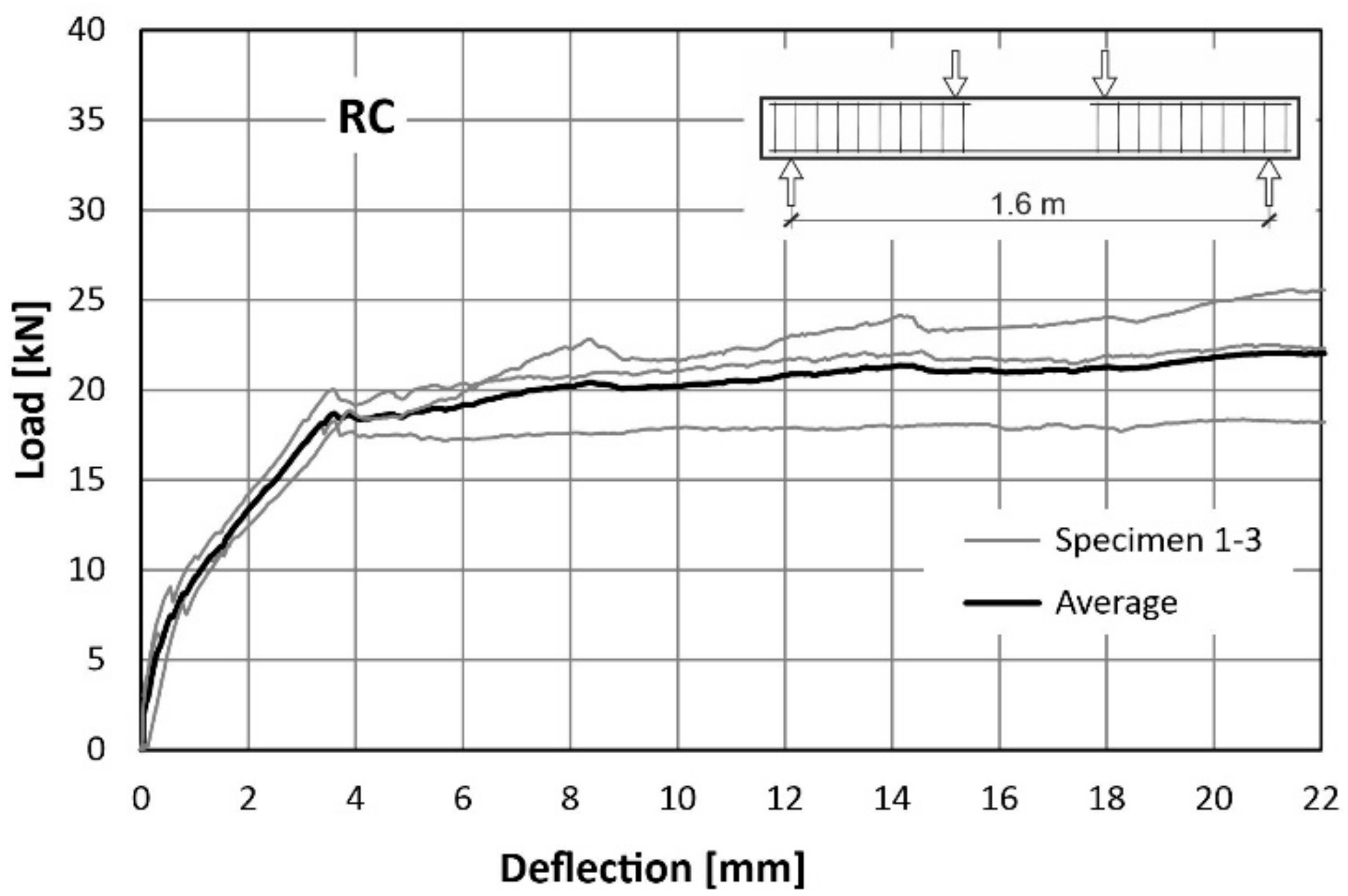
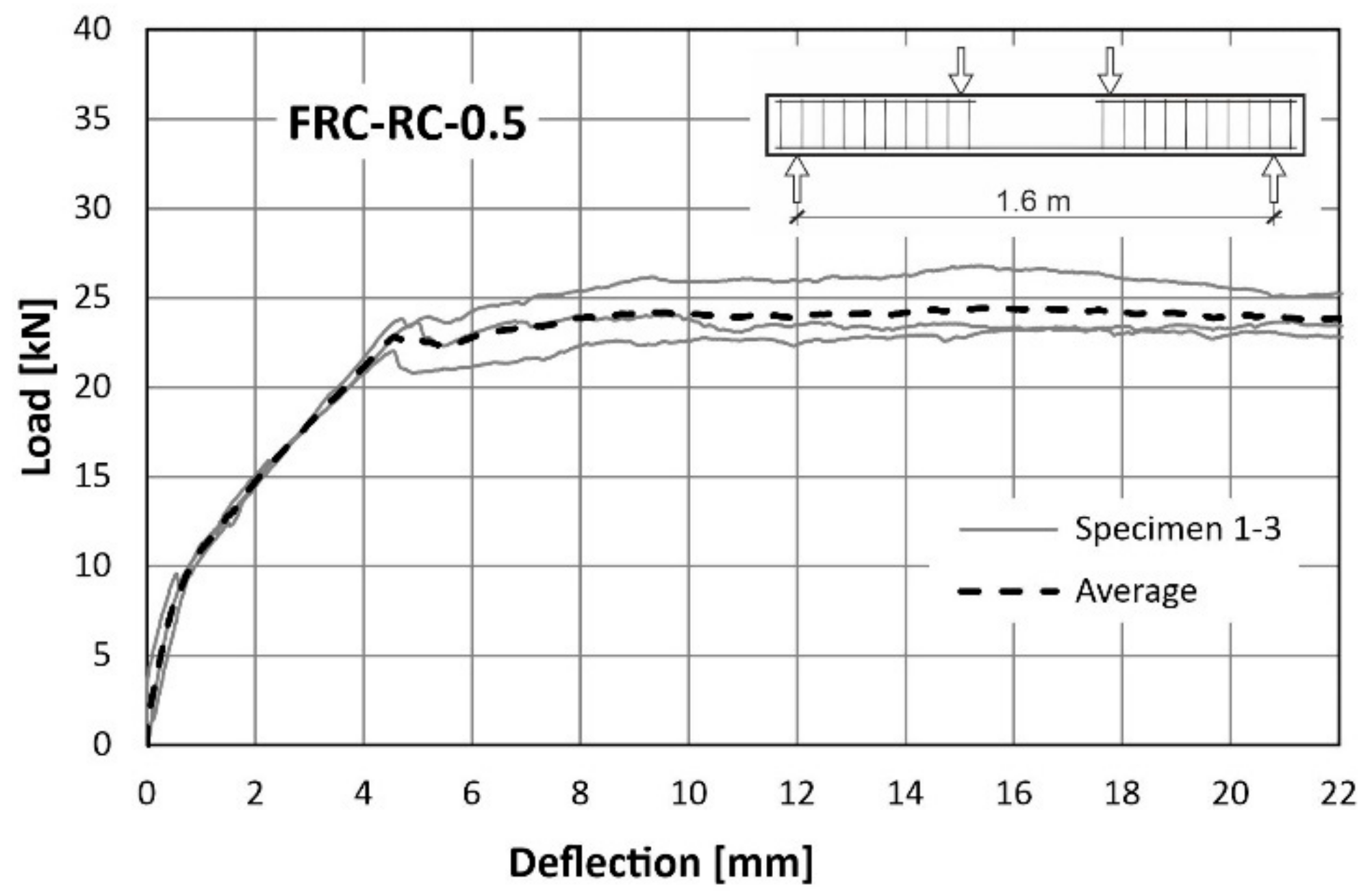
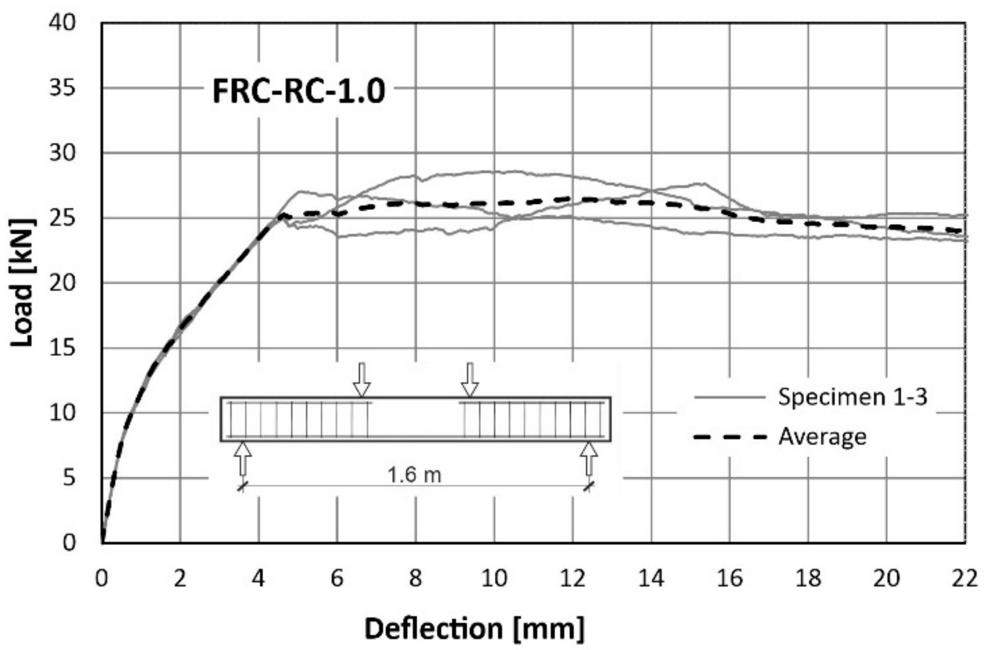
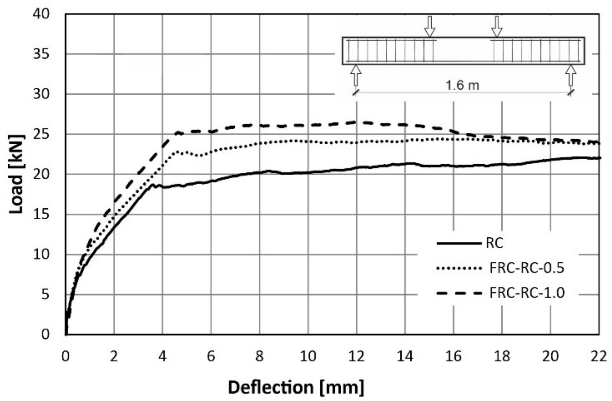
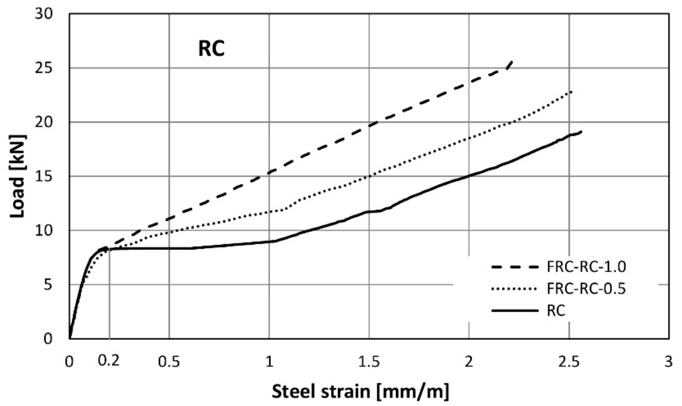
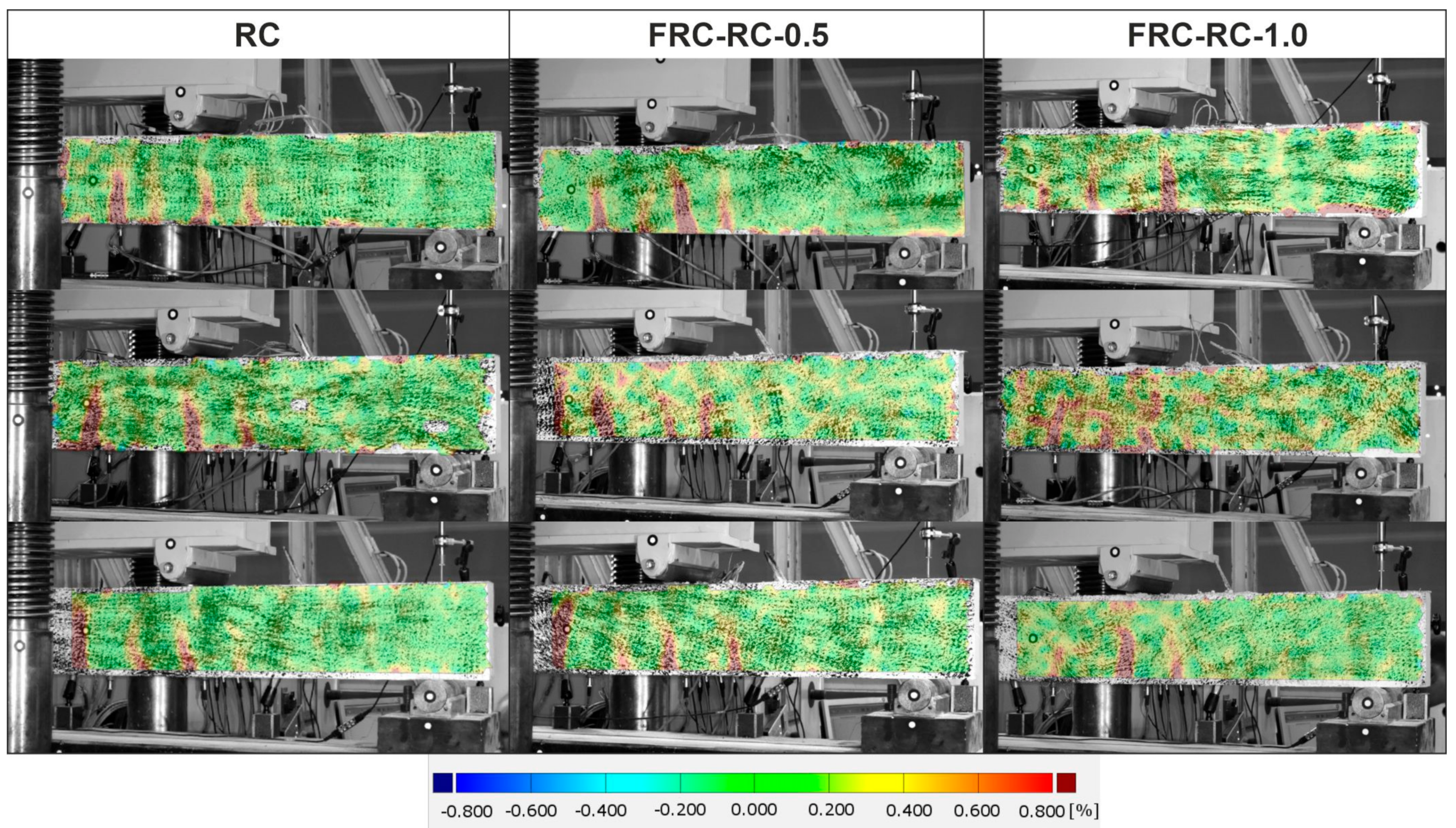
3.2.2. Beams Reinforced with Fibres and Longitudinal Reinforcement
4. Conclusions
- The addition of the fibres resulted in an increase of the load-bearing capacity of the RC beams. The maximum load went from 22.93 kN on average for RC beams to 27.77 kN on average for the FRC-RC-1.0 beams This demonstrates the efficiency of the fibres even at the ultimate limit state. For the same load, the strains in steel bars were lower in the beams where RSF were applied;
- In the beams with a 1.6 m span the application of RSF had no apparent influence on the distance between the cracks and their number;
- The beams reinforced only with the RSF were able to carry the loads after cracking. The maximum load recorded was equal to around 7 kN. Only one crack was noted in the brittle failure of all FRC beams.
Author Contributions
Funding
Institutional Review Board Statement
Informed Consent Statement
Data Availability Statement
Conflicts of Interest
References
- Celeiro, M.; Armada, D.; Dagnac, T.; de Boer, J.; Llompart, M. Hazardous compounds in recreational and urban recycled surfaces made from crumb rubber. Compliance with current regulation and future perspectives. Sci. Total Environ. 2021, 755, 142566. [Google Scholar] [CrossRef] [PubMed]
- Eisa, A.S.; Elshazli, M.T.; Nawar, M.T. Experimental investigation on the effect of using crumb rubber and steel fibers on the structural behavior of reinforced concrete beams. Constr. Build. Mater. 2020, 252, 119078. [Google Scholar] [CrossRef]
- Strukar, K.; Šipoš, T.K.; Dokšanović, T.; Rodrigues, H. Experimental Study of Rubberized Concrete Stress-Strain Behavior for Improving Constitutive Models. Materials 2018, 11, 2245. [Google Scholar] [CrossRef] [PubMed] [Green Version]
- Brandt, A.M. Fibre reinforced cement-based (FRC) composites after over 40 years of development in building and civil engineering. Compos. Struct. 2008, 86, 3–9. [Google Scholar] [CrossRef]
- Holschemacher, K.; Mueller, T.; Ribakov, Y. Effect of steel fibres on mechanical properties of high-strength concrete. Mater. Des. 2010, 31, 2604–2615. [Google Scholar] [CrossRef]
- Domski, J.; Katzer, J.; Zakrzewski, M.; Ponikiewski, T. Comparison of the mechanical characteristics of engineered and waste steel fiber used as reinforcement for concrete. J. Clean. Prod. 2017, 158, 18–28. [Google Scholar] [CrossRef]
- Groli, G.; Caldentey, A.P.; Soto, A.G. Cracking performance of SCC reinforced with recycled fibres-an experimental study. Struct. Concr. 2014, 15, 136–153. [Google Scholar] [CrossRef]
- Mastali, M.; Dalvand, A.; Sattarifard, A.; Abdollahnejad, Z.; Illikainen, M. Characterization and optimization of hardened properties of self-consolidating concrete incorporating recycled steel, industrial steel, polypropylene and hybrid fibers. Compos. Part Eng. 2018, 151, 186–200. [Google Scholar] [CrossRef]
- Martinelli, E.; Caggiano, A.; Xargay, H. An experimental study on the post-cracking behaviour of Hybrid Industrial/Recycled Steel Fibre-Reinforced Concrete. Constr. Build. Mater. 2015, 94, 290–298. [Google Scholar] [CrossRef]
- Centonze, G.; Leone, M.; Aiello, M. Steel fibers from waste tires as reinforcement in concrete: A mechanical characterization. Constr. Build. Mater. 2012, 36, 46–57. [Google Scholar] [CrossRef]
- Pająk, M. Concrete reinforced with various amounts of steel fibers reclaimed from end-of-life tires. In Proceedings of the MATEC Web Conference, Sibiu, Romania, 5–7 June 2019; p. 262. [Google Scholar] [CrossRef]
- Pająk, M. Research on concrete reinforced with fibers from end-of-life tires. Inżynieria Bud. 2018, 74, 267–270. [Google Scholar]
- Pająk, M.; Krystek, M.; Zakrzewski, M.; Domski, J. Laboratory Investigation and Numerical Modelling of Concrete Reinforced with Recycled Steel Fibers. Materials 2021, 14, 1828. [Google Scholar] [CrossRef] [PubMed]
- El-Sayed, T.A. Flexural behavior of RC beams containing recycled industrial wastes as steel fibers. Constr. Build. Mater. 2019, 212, 27–38. [Google Scholar] [CrossRef]
- Folino, P.; Ripani, M.; Xargay, H.; Rocca, N. Comprehensive analysis of Fiber Reinforced Concrete beams with conventional reinforcement. Eng. Struct. 2020, 202, 109862. [Google Scholar] [CrossRef]
- Junaid, M.T.; Elbana, A.; Altoubat, S.; Al-Sadoon, Z. Experimental study on the effect of matrix on the flexural behavior of beams reinforced with Glass Fiber Reinforced Polymer (GFRP) bars. Compos. Struct. 2019, 222, 110930. [Google Scholar] [CrossRef]
- Küsel, F.; Kearsley, E. Effect of steel fibres in combination with different reinforcing ratios on the performance of continuous beams. Constr. Build. Mater. 2019, 227, 116553. [Google Scholar] [CrossRef]
- Cardoso, D.C.; Pereira, G.B.; Silva, F.A.; Filho, J.J.S.; Pereira, E.V. Influence of steel fibers on the flexural behavior of RC beams with low reinforcing ratios: Analytical and experimental investigation. Compos. Struct. 2019, 222, 110926. [Google Scholar] [CrossRef]
- Elbehiry, A.; Elnawawy, O.; Kassem, M.; Zaher, A.; Uddin, N.; Mostafa, M. Performance of concrete beams reinforced using banana fiber bars. Case Stud. Constr. Mater. 2020, 13, e00361. [Google Scholar] [CrossRef]
- Meza, A.; Siddique, S. Effect of aspect ratio and dosage on the flexural response of FRC with recycled fiber. Constr. Build. Mater. 2019, 213, 286–291. [Google Scholar] [CrossRef]
- European Committee for Standartization. European Committee for Standartization EN 12350-5 Testing Fresh Concrete-Part 5: Flow Table Test. European Standard; European Committee for Standartization: Brussels, Belgium, 2009. [Google Scholar]
- British Standards Institution. British Standards Institution BS EN 12390-3: 2009. Test. Hardened Concrete Part 3 Compressive Strength Test Specimens; British Standards Institution: London, UK, 2009. [Google Scholar]
- European Committee for Standartization. EN 14651. In Test Method for Metallic Fibered Concrete-Measuring the Flexural Tensile Strength (Limit or Proportionality (LOP), Residual); European Committee for Standartization: Brussels, Belgium, 2005. [Google Scholar]
- Taheri, M.; Barros, J.A.; Salehian, H. Integrated approach for the prediction of crack width and spacing in flexural FRC members with hybrid reinforcement. Eng. Struct. 2020, 209, 110208. [Google Scholar] [CrossRef]
- Walvaren, J. Model Code 2010, final drafts. FIB Bull. 2012, 1, 1–2. [Google Scholar]
- European Committee for Standartization. EN 14889-1. In Fibres for Concrete-Part 1: Steel fibres-Definitions, Specifications and Conformity; European Committee for Standartization: Brussels, Belgium, 2006. [Google Scholar]


| Mix | Cement [kg/m3] | Sand [kg/m3] | Coarse Aggregate [kg/m3] | Silica Fume [kg/m3] | Superplasticizer | Water [L/m3] | Fibres | |
|---|---|---|---|---|---|---|---|---|
| [kg/m3] | Volume Ratio Vf | |||||||
| C-0 | 300 | 840 | 892 | 80 | 2.55 | 165 | 0 | 0 |
| FRC-0.5 | 39.25 | 0.5% | ||||||
| FRC-1.0 | 78.5 | 1.0% | ||||||
| Length [mm] | Diameter [mm] | Tensile Strength [MPa] | Aspect Ratio (Length/Diameter) | Longitudinal Shape |
|---|---|---|---|---|
| ~2–50 | 0.15 ± 5% | ≥2850 | 13–200 | irregular (curved, twisted) |
| Mix | Fibres Volume Ratio Vf | Slump Flow [mm] |
|---|---|---|
| C-0 | 0 | 495 |
| FRC-0.5 | 0.5% | 440 |
| FRC-1.0 | 1.0% | 375 |
| Mix | Fibres Reinforcement—Fibres Volume Ratio Vf | View of the Beam | Longitudinal Reinforcement—Bars | Shear Reinforcement—Stirrups | Number of Beams |
|---|---|---|---|---|---|
| FRC-0.5 | 0.5% |  | - | - | 3 |
| FRC-1.0 | 1.0% | - | - | 3 | |
| RC-0 | 0 | 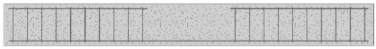 | 2 ø 6 mm | ø 4 mm every 70 mm | 3 |
| FRC-RC-0.5 | 0.5% | 2 ø 6 mm | ø 4 mm every 70 mm | 3 | |
| FRC-RC-1.0 | 1.0% | 2 ø 6 mm | ø 4 mm every 70 mm | 3 |
| Mix | Fibres Reinforcement—Fibres Volume Ratio Vf [%] | Compressive Strength [MPa] | Strain Corresponding to Compressive Strength [10−3] |
|---|---|---|---|
| C-0 | 0 | 31.36 (4) | 1.9 (7) |
| FRC-0.5 | 0.5 | 31.76 (2) | 2.1 (5) |
| FRC-1.0 | 1.0 | 30.82 (5) | 1.9 (19) |
| Mix | Fibres Reinforcement—Fibres Volume Ratio Vf [%] | Limit of Proportionality [MPa] | Residual Flexural Tensile Strength [MPa] | fR.3/fR.1 | fR.1/fL | |||
|---|---|---|---|---|---|---|---|---|
| fL | fR.1 | fR.2 | fR.3 | fR.4 | ||||
| C-0 | 0 | 2.95 | - | - | - | - | - | - |
| FRC-0.5 | 0.5 | 3.26 | 2.02 > 1.5 | 1.86 | 1.43 | 1.18 > 1.0 | 0.71 > 0.5 | 0.62 > 0.4 |
| FRC-1.0 | 1.0 | 3.42 | 2.99 > 1.5 | 2.7 | 2.43 | 1.71 > 1.0 | 0.81 > 0.5 | 0.87 > 0.4 |
| Mix | Maximum Total Load [kN] | Bending Moment [kNm] | Deflection Corresponding to the εc = 0.2‰ |
|---|---|---|---|
| FRC-0.5 | 7.09 (1) | 1.95 | 0.3 |
| FRC-1.0 | 7.26 (1) | 2.00 | 0.72 |
| RC | 22.93 (5) | 6.31 | 3.61 |
| FRC-RC-0.5 | 24.84 (2) | 6.83 | 4.57 |
| FRC-RC-1.0 | 27.77 (1) | 7.64 | 4.64 |
Publisher’s Note: MDPI stays neutral with regard to jurisdictional claims in published maps and institutional affiliations. |
© 2021 by the authors. Licensee MDPI, Basel, Switzerland. This article is an open access article distributed under the terms and conditions of the Creative Commons Attribution (CC BY) license (https://creativecommons.org/licenses/by/4.0/).
Share and Cite
Pająk, M.; Wandzik, G. Laboratory Tests of Concrete Beams Reinforced with Recycled Steel Fibres and Steel Bars. Materials 2021, 14, 6752. https://doi.org/10.3390/ma14226752
Pająk M, Wandzik G. Laboratory Tests of Concrete Beams Reinforced with Recycled Steel Fibres and Steel Bars. Materials. 2021; 14(22):6752. https://doi.org/10.3390/ma14226752
Chicago/Turabian StylePająk, Małgorzata, and Grzegorz Wandzik. 2021. "Laboratory Tests of Concrete Beams Reinforced with Recycled Steel Fibres and Steel Bars" Materials 14, no. 22: 6752. https://doi.org/10.3390/ma14226752
APA StylePająk, M., & Wandzik, G. (2021). Laboratory Tests of Concrete Beams Reinforced with Recycled Steel Fibres and Steel Bars. Materials, 14(22), 6752. https://doi.org/10.3390/ma14226752