
Modeling of Melt Flow and Heat Transfer in Stationary Gas Tungsten Arc Welding with Vertical and Tilted Torches


Abstract
:1. Introduction
2. Numerical Details
3. Governing Equations
- The arc is steady and in LTE;
- The flow is turbulent in the arc and laminar in the weld pool region;
- The length of the tungsten electrode tip surrounded by the arc plasma is the same for the 90° and 70° torch angles;
- The filler wire and the workpiece material are assumed to have similar properties;
3.1. Governing Equations of the Arc Plasma
3.2. Governing Equations of the Filler Wire
3.3. Governing Equations of the Weld Pool
4. Simulation Models
4.1. Model of the Arc Plasma
4.2. Model of Heat Transfer to the Filler Wire
4.3. Model of the Weld Pool
4.4. Boundary Conditions
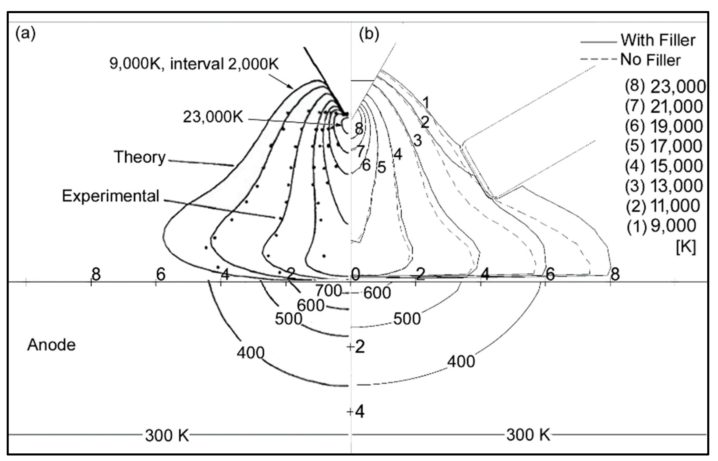
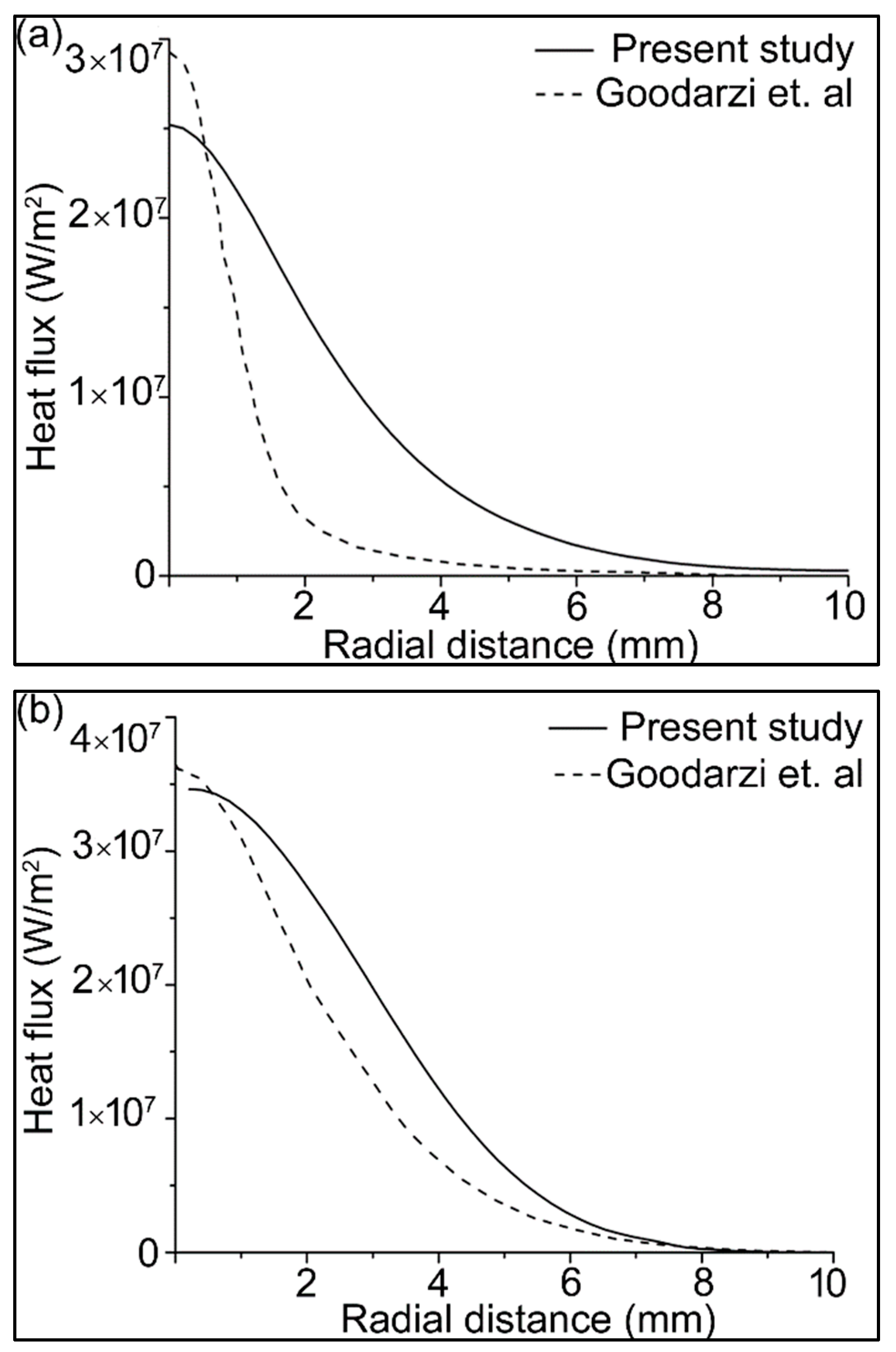
5. Model Validation
6. Results and Discussion
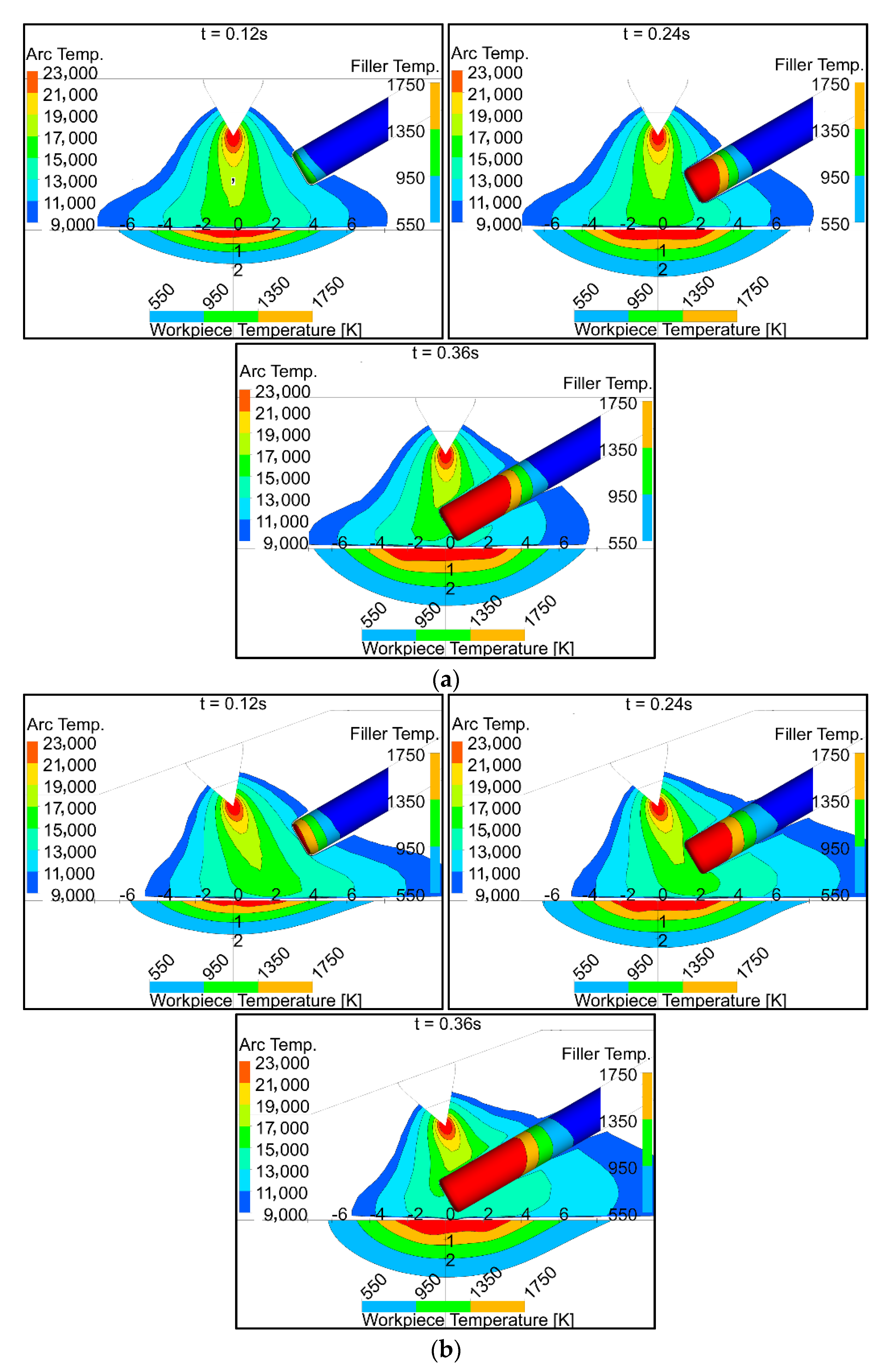
6.1. Temperatures in the Arc, Filler Wire, and Workpiece
6.2. Convective Heat Flux to the Filler Wire
6.3. Electron Heat Flux to the Filler Wire
6.4. Total Heat Flux to the Filler Wire
6.5. Convective Heat Flux to the Workpiece
6.6. Electron Heat Flux to the Workpiece
6.7. Total Heat Flux to the Workpiece
6.8. The Weld Pool Shapes
7. Conclusions
Author Contributions
Funding
Institutional Review Board Statement
Informed Consent Statement
Data Availability Statement
Conflicts of Interest
References
- Traidia, A.; Roger, F.; Guyot, E.; Schroeder, J.; Lubineau, G. Hybrid 2D–3D modelling of GTA welding with filler wire addition. Int. J. Heat Mass Transf. 2012, 55, 3946–3963. [Google Scholar] [CrossRef]
- Pamnani, R.; Jayakumar, T.; Vasudevan, M.; Sakthivel, T. Investigations on the impact toughness of HSLA steel arc welded joints. J. Manuf. Process. 2016, 21, 75–86. [Google Scholar] [CrossRef]
- Luo, C.; Li, H.; Song, Y.; Yang, L.; Wen, Y. Microstructure and Performance Analysis of Welded Joint of Spray-Deposited 2195 Al-Cu-Li Alloy Using GTAW. Metals 2020, 10, 1236. [Google Scholar] [CrossRef]
- Zhang, M.; Zhou, Y.; Huang, C.; Chu, Q.; Zhang, W.; Li, J. Simulation of Temperature Distribution and Microstructure Evolution in the Molten Pool of GTAW Ti-6Al-4V Alloy. Materials 2018, 11, 2288. [Google Scholar] [CrossRef] [Green Version]
- Filho, J.D.C.P.; Passos, E.K.D.; Gonzaga, R.S.; Ferreira, R.F.; Santos, D.D.; Juliano, D.R. Ultrasonic Inspection of a 9% Ni Steel Joint Welded with Ni-based Superalloy 625: Simulation and Experimentation. Metals 2018, 8, 787. [Google Scholar] [CrossRef] [Green Version]
- Jian, X.; Wu, H. Influence of the Longitudinal Magnetic Field on the Formation of the Bead in Narrow Gap Gas Tungsten Arc Welding. Metals 2020, 10, 1351. [Google Scholar] [CrossRef]
- Siddiqui, I.H.; Maurya, A.; Ashraf, M.; Asiri, F. Modeling of Inclusion Motion Under Interfacial Tension in a Flash Welding Process. In Advanced Computational Methods in Mechanical and Materials Engineering; CRC Press: New York, NY, USA, 2021; pp. 91–110. [Google Scholar]
- Siddiqui, I.H.; Geleta, D.D.; Bae, G.; Lee, J. Numerical Modeling of the Inclusion Behavior during AC Flash Butt Welding. ISIJ Int. 2020, 60, 2503–2511. [Google Scholar] [CrossRef]
- Kohandehghan, A.R.; Serajzadeh, S. Effects of Different Heat Flux Schemes in Modelling of Transport Phenomena during Gas Tungsten Arc Welding of AA1050. Proc. Inst. Mech. Eng. Part B J. Eng. Manuf. 2010, 224, 1537–1553. [Google Scholar] [CrossRef]
- Silwal, B.; Santangelo, M. Effect of vibration and hot-wire gas tungsten arc (GTA) on the geometric shape. J. Mater. Process. Technol. 2018, 251, 138–145. [Google Scholar] [CrossRef]
- Siddiqui, M.I.H.; Alshehri, H.; Orfi, J.; Ali, M.; Dobrotă, D. Computational Fluid Dynamics (CFD) Simulation of Inclusion Motion under Interfacial Tension in a Flash Welding Process. Metals 2021, 11, 1073. [Google Scholar] [CrossRef]
- Jian, X.; Yang, X.; Li, J.; Wang, W.; Wu, H. Numerical Analysis of the Heating Characteristics of Magnetic Oscillation Arc and the Fluid Flow in Molten Pool in Narrow Gap Gas Tungsten Arc Welding. Materials 2020, 13, 5799. [Google Scholar] [CrossRef] [PubMed]
- Cheng, S.; Cheng, F.; Li, L.; Li, F.; Shao, Z.; Zhang, Y.; Wu, S. Relationship Analysis between Multi-Parameters and Ferrite Number in GTAW Based on ANN Model. Metals 2021, 11, 1429. [Google Scholar] [CrossRef]
- Wu, D.; Tashiro, S.; Wu, Z.; Nomura, K.; Hua, X.; Tanaka, M. Analysis of heat transfer and material flow in hybrid KPAW-GMAW process based on the novel three dimensional CFD simulation. Int. J. Heat Mass Transf. 2020, 147, 118921. [Google Scholar] [CrossRef]
- Satyanarayana, G.; Narayana, K.; Rao, B.N. Incorporation of Taguchi approach with CFD simulations on laser welding of spacer grid fuel rod assembly. Mater. Sci. Eng. B 2021, 269, 115182. [Google Scholar] [CrossRef]
- Cho, W.-I.; Na, S.-J. Impact of driving forces on molten pool in gas metal arc welding. Weld. World 2021, 65, 1735–1747. [Google Scholar] [CrossRef]
- Cho, D.-W.; Na, S.-J. Molten pool behaviors for second pass V-groove GMAW. Int. J. Heat Mass Transf. 2015, 88, 945–956. [Google Scholar] [CrossRef]
- Xu, G.; Hu, J.; Tsai, H. Three-dimensional modeling of arc plasma and metal transfer in gas metal arc welding. Int. J. Heat Mass Transf. 2009, 52, 1709–1724. [Google Scholar] [CrossRef]
- Han, Y.; Chen, J.; Li, L.; Wang, L.; Wu, C. Numerical Investigation of Arc-Pool-Metal Vapor Behavior in GTAW with an External Magnetic Field. Metals 2020, 10, 1199. [Google Scholar] [CrossRef]
- Fei, Z.; Pan, Z.; Cuiuri, D.; Li, H.; Gazder, A.A. A Combination of Keyhole GTAW with a Trapezoidal Interlayer: A New Insight into Armour Steel Welding. Materials 2019, 12, 3571. [Google Scholar] [CrossRef] [Green Version]
- Campagnolo, A.; Ferro, P.; Romanin, L.; Meneghetti, G. Residual Notch Stress Intensity Factors in Welded Joints Evaluated by 3D Numerical Simulations of Arc Welding Processes. Materials 2021, 14, 812. [Google Scholar] [CrossRef]
- Wu, F.; Flint, T.F.; Falch, K.V.; Smith, M.C.; Drakopoulos, M.; Mirihanage, W. Mapping flow evolution in gas tungsten arc weld pools. Int. J. Heat Mass Transf. 2021, 179, 121679. [Google Scholar] [CrossRef]
- Nemchinsky, V.A. Heat transfer in a liquid droplet hanging at the tip of an electrode during arc welding. J. Phys. D Appl. Phys. 1997, 30, 1120–1124. [Google Scholar] [CrossRef]
- Kang, S.H.; Cho, H.S. Analytical solution for transient temperature distribution in gas tungsten arc welding with consideration of filler wire. Proc. Inst. Mech. Eng. Part B J. Eng. Manuf. 1999, 213, 799–811. [Google Scholar] [CrossRef]
- Yudodibroto, B.Y.B.; Hermans, M.J.M.; Hirata, Y.; Ouden, G.D. Influence of filler wire addition on weld pool oscillation during gas tungsten arc welding. Sci. Technol. Weld. Join. 2004, 9, 163–168. [Google Scholar] [CrossRef]
- Wu, C.; Yan, F. Numerical simulation of transient development and diminution of weld pool in gas tungsten arc welding. Model. Simul. Mater. Sci. Eng. 2003, 12, 13–20. [Google Scholar] [CrossRef] [Green Version]
- Fan, H.G.; Kovacevic, R. Three-dimensional model for gas tungsten arc welding with filler metal. Proc. Inst. Mech. Eng. Part B J. Eng. Manuf. 2006, 220, 1107–1115. [Google Scholar] [CrossRef]
- Traidia, A.; Roger, F. Numerical and experimental study of arc and weld pool behaviour for pulsed current GTA welding. Int. J. Heat Mass Transf. 2011, 54, 2163–2179. [Google Scholar] [CrossRef]
- Chen, J.S.; Lu, Y.; Li, X.R.; Zhang, Y.M. Gas tungsten arc welding using an arcing wire. Weld. J. 2012, 91, 261–269. [Google Scholar]
- Parvez, S.; Abid, M.; Nash, D.H.; Fawad, H.; Galloway, A. Effect of Torch Angle on Arc Properties and Weld Pool Shape in Stationary GTAW. J. Eng. Mech. 2013, 139, 1268–1277. [Google Scholar] [CrossRef] [Green Version]
- Lu, F.; Wang, H.-P.; Murphy, A.B.; Carlson, B.E. Analysis of energy flow in gas metal arc welding processes through self-consistent three-dimensional process simulation. Int. J. Heat Mass Transf. 2014, 68, 215–223. [Google Scholar] [CrossRef]
- Chen, B.-Q.; Hashemzadeh, M.; Soares, C.G. Numerical and experimental studies on temperature and distortion patterns in butt-welded plates. Int. J. Adv. Manuf. Technol. 2014, 72, 1121–1131. [Google Scholar] [CrossRef]
- Shimomura, S.; Minomo, T.; Takigawa, Y.; Uesugi, T.; Ueda, M.; Kinomoto, Y.; Higashi, K. Influence of Filler Rod Composition on the Strength of Tungsten Inert Gas Welded Magnesium Alloy Joint. Adv. Mater. Res. 2014, 922, 663–666. [Google Scholar] [CrossRef]
- Nomura, K.; Kishi, T.; Shirai, K.; Hirata, Y.; Kataoka, K. Temperature measurement of asymmetrical pulsed TIG arc plasma by multidirectional monochromatic imaging method. Weld. World 2015, 59, 283–293. [Google Scholar] [CrossRef]
- Murphy, A.B.; Thomas, D.G. Prediction of arc, weld pool and weld properties with a desktop computer model of metal–inert-gas welding. Weld. World 2017, 61, 623–633. [Google Scholar] [CrossRef]
- Ishak, M.; Salleh, M.; Aisha, S. The mechanical and microstructural study of welded AA7075 using different filler metals. Int. J. Comput. Methods Exp. Meas. 2017, 5, 696–712. [Google Scholar] [CrossRef]
- Trushnikov, D.; Perminov, A.; Pang, S.; Karunakaran, K.P.; Belenkiy, V.; Permyakov, G.; Kartashov, M.; Matveev, E.; Dushina, A.; Schitsyn, Y. Modelling of Heat and Mass Transfer for Wire-Based Additive Manufacturing Using Electric Arc and Concentrated Sources of Energy. Int. J. Eng. Technol. 2018, 7, 741. [Google Scholar] [CrossRef] [Green Version]
- Saheb, S.H.; Chandrashekhar, A. Experimental study on influence of filler rods in gas Tungsten Arc welding. In AIP Conference Proceedings; AIP Publishing LLC: Coimbatore, India, 2019; Volume 2166, p. 020007. [Google Scholar] [CrossRef]
- Han, Y.; Chen, J.; Ma, H.; Zhao, X.; Wu, C.; Gao, J. Numerical Simulation of Arc and Droplet Behaviors in TIG-MIG Hybrid Welding. Materials 2020, 13, 4520. [Google Scholar] [CrossRef]
- Khorrami, M.S.; Mostafaei, M.A.; Pouraliakbar, H.; Kokabi, A.H. Study on microstructure and mechanical characteristics of low-carbon steel and ferritic stainless steel joints. Mater. Sci. Eng. A 2014, 608, 35–45. [Google Scholar] [CrossRef]
- Liang, P.; Trelles, J.P. 3D numerical investigation of a free-burning argon arc with metal electrodes using a novel sheath coupling procedure. Plasma Sources Sci. Technol. 2019, 28, 115012. [Google Scholar] [CrossRef]
- Tuček, P.; Janoška, Z. Fractal dimension as a descriptor of urban growth dynamics. Neural Netw. World 2013, 23, 93–102. [Google Scholar] [CrossRef] [Green Version]
- Benilov, M.S. Modeling the physics of interaction of high-pressure arcs with their electrodes: Advances and challenges. J. Phys. D Appl. Phys. 2019, 53, 013002. [Google Scholar] [CrossRef]
- Santos, D.F.; Lisnyak, M.; Almeida, N.A.; Benilova, L.G.; Benilov, M.S. Numerical investigation of AC arc ignition on cold electrodes in atmospheric-pressure argon. J. Phys. D Appl. Phys. 2021, 54, 195202. [Google Scholar] [CrossRef]
- Saifutdinov, A.I. Unified simulation of different modes in atmospheric pressure DC discharges in nitrogen. J. Appl. Phys. 2021, 129, 093302. [Google Scholar] [CrossRef]
- Khan, M.; Dewan, M.W.; Sarkar, Z. Effects of welding technique, filler metal and post-weld heat treatment on stainless steel and mild steel dissimilar welding joint. J. Manuf. Process. 2021, 64, 1307–1321. [Google Scholar] [CrossRef]
- Kanouff, M.; Greif, R. The unsteady development of a GTA weld pool. Int. J. Heat Mass Transf. 1992, 35, 967–979. [Google Scholar] [CrossRef]
- Murphy, A.B.; Arundelli, C.J. Transport coefficients of argon, nitrogen, oxygen, argon-nitrogen, and argon-oxygen plasmas. Plasma Chem. Plasma Process. 1994, 14, 451–490. [Google Scholar] [CrossRef]
- Properties for LMFBR Safety Analysis. Thermodynamic, Transport, Mechanical; OSTI: Argonne, IL, USA, 1976. [CrossRef] [Green Version]
- Zhou, X.; Zhang, H.; Wang, G.; Bai, X. Three-dimensional numerical simulation of arc and metal transport in arc welding based additive manufacturing. Int. J. Heat Mass Transf. 2016, 103, 521–537. [Google Scholar] [CrossRef]
- ANSYS CFX, Academic Research, Release 17.0, Help System, ANSYS CFX-Solver Theory Guide; ANSYS Inc.: Canonsburg, PA, USA, 2017.
- Li, S.; Hu, L.; Dai, P.; Bi, T.; Deng, D. Influence of the groove shape on welding residual stresses in P92/SUS304 dissimilar metal butt-welded joints. J. Manuf. Process. 2021, 66, 376–386. [Google Scholar] [CrossRef]
- Moayedi, H.; Darabi, R.; Ghabussi, A.; Habibi, M.; Foong, L.K. Weld orientation effects on the formability of tailor welded thin steel sheets. Thin-Walled Struct. 2020, 149, 106669. [Google Scholar] [CrossRef]
- Chakraborty, N.; Chakraborty, S.; Dutta, P. Modelling of turbulent transport in arc welding pools. Int. J. Numer. Methods Heat Fluid Flow 2003, 13, 7–30. [Google Scholar] [CrossRef]
- Gonzalez, J.J.; Lago, F.; Freton, P.; Masquère, M.; Franceries, X. Numerical modelling of an electric arc and its interaction with the anode: Part II. The three-dimensional model—Influence of external forces on the arc column. J. Phys. D Appl. Phys. 2005, 38, 306–318. [Google Scholar] [CrossRef]
- Quigley, M.B.C.; Richards, P.H.; Swift-Hook, D.T.; Gick, A.E.F. Heat flow to the workpiece from a TIG welding arc. J. Phys. D Appl. Phys. 1973, 6, 2250–2258. [Google Scholar] [CrossRef]
- Abid, M.; Parvez, S.; Nash, D.H.; Fawad, H.F. 3D simulation of stationary gas tungsten arc welding of L-shape, V-shape and open-corner joints. Proc. Inst. Mech. Eng. Part B J. Eng. Manuf. 2012, 226, 1354–1368. [Google Scholar] [CrossRef]
- Goodarzi, M.; Choo, R.; Toguri, J.M. The effect of the cathode tip angle on the GTAW arc and weld pool: I. Mathematical model of the arc. J. Phys. D Appl. Phys. 1997, 30, 2744–2756. [Google Scholar] [CrossRef]
- Lowke, J.J.; Morrow, R.; Haidar, J. A simplified unified theory of arcs and their electrodes. J. Phys. D Appl. Phys. 1997, 30, 2033–2042. [Google Scholar] [CrossRef]


| Parameters | Value |
|---|---|
| Arc length | 5 mm |
| Welding current | 200 A |
| Argon flow | 14 lt/min |
| Torch angle | 90° and 70° |
| Tip angle | 60° |
| Electrode diameter | 3.2 mm |
| Filler wire diameter | 2 mm |
| Filler wire angle | 30° |
| Filler wire feed rate | 100 cm/min |
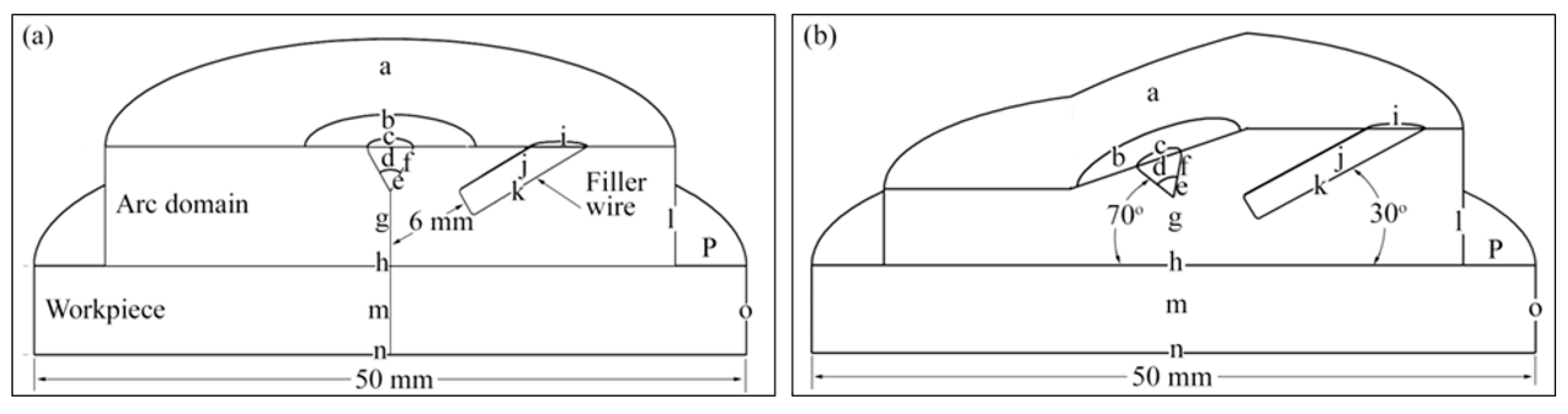
| Boundary | Description |
|---|---|
| a | Top of the arc domain |
| b | Nozzle opening |
| c | Tungsten electrode cross-section |
| d | Tungsten electrode front symmetry plane |
| e | Tungsten electrode tip surrounded by the plasma |
| f | Arc–electrode interface |
| g | Arc front symmetry plane |
| h | Arc–workpiece interface |
| i | Filler rod cross-section |
| j | Filler rod front symmetry plane |
| k | Arc–filler rod interface |
| l | Outer of the arc domain |
| m | Workpiece front symmetry plane |
| n | Bottom of the workpiece |
| o | Exterior of the workpiece |
| p | Top of the workpiece |
| Arc Domain (Fluid) | Torch Domain (Solid) | |||||||||
|---|---|---|---|---|---|---|---|---|---|---|
| Opening | Inlet | Sym. | Opening | Wall | Sym. | Interface | Interface | |||
| Equation No. | Boundary Variable | Units | a | b | g | l | c | d | e | f |
| (1) and (2) | U | m/s | - | - | - | - | - | - | ||
| p | Pa | - | - | - | - | - | - | |||
| (3) | T | K | 303 | 303 | 303 | 3000 | - | - | ||
| q | W/m2 | - | - | - | - | - | - | 0 | 0 | |
| (12) and (13) | E | V/m | 0 | 0 | - | 0 | - | constant | 0 | |
| V | Volt | - | - | - | - | - | - | - | ||
| A/m2 | - | - | - | - | - | -- | - | |||
| (14) | B | A/m | Bn | Bn | Constant | - | Bn | constant | ||
| T m | - | - | - | 0 | - | - | - | - | ||
| Filler Wire Domain (Solid) | Workpiece Domain (Fluid) | |||||||||
|---|---|---|---|---|---|---|---|---|---|---|
| Wall | Sym. | Wall | Wall | Sym. | Wall | Wall | Wall | |||
| Equation No. | Boundary Variable | Units | i | j | k | h | m | n | o | p |
| (15) and (16) | U | m/s | - | - | - | - | 0 | 0 | 0 | |
| p | Pa | - | - | - | Gas drag + Ma | - | - | - | - | |
| (17) and (19) | T | K | 303 | - | - | 303 | 303 | 303 | ||
| q | W/m2 | - | - | - | - | - | - | |||
| hc | W/m2K | - | - | - | - | - | 20 | 20 | 20 | |
| (12) and (13) | E | V/m | - | - | - | - | - | - | 0 | 0 |
| V | Volt | - | - | - | - | - | Ground | - | - | |
| J | A/m2 | - | - | - | - | - | - | - | ||
| (14) | B | A/m | - | - | - | Bn | Constant | Bn | - | Bn |
| T m | - | - | - | - | - | - | 0 | - | ||
Publisher’s Note: MDPI stays neutral with regard to jurisdictional claims in published maps and institutional affiliations. |
© 2021 by the authors. Licensee MDPI, Basel, Switzerland. This article is an open access article distributed under the terms and conditions of the Creative Commons Attribution (CC BY) license (https://creativecommons.org/licenses/by/4.0/).
Share and Cite
Parvez, S.; Siddiqui, M.I.H.; Ali, M.A.; Dobrotă, D. Modeling of Melt Flow and Heat Transfer in Stationary Gas Tungsten Arc Welding with Vertical and Tilted Torches. Materials 2021, 14, 6845. https://doi.org/10.3390/ma14226845
Parvez S, Siddiqui MIH, Ali MA, Dobrotă D. Modeling of Melt Flow and Heat Transfer in Stationary Gas Tungsten Arc Welding with Vertical and Tilted Torches. Materials. 2021; 14(22):6845. https://doi.org/10.3390/ma14226845
Chicago/Turabian StyleParvez, Shahid, Md Irfanul Haque Siddiqui, Masood Ashraf Ali, and Dan Dobrotă. 2021. "Modeling of Melt Flow and Heat Transfer in Stationary Gas Tungsten Arc Welding with Vertical and Tilted Torches" Materials 14, no. 22: 6845. https://doi.org/10.3390/ma14226845