
Requirements for Processing High-Strength AlZnMgCu Alloys with PBF-LB/M to Achieve Crack-Free and Dense Parts

 ,
,  , , and
Abstract
:1. Introduction
2. Materials and Methods
2.1. Mechanical Decoration of the Powder
2.2. Laser Beam Melting of Specimens
2.3. Characterization of Powder and Specimens
3. Results and Discussion
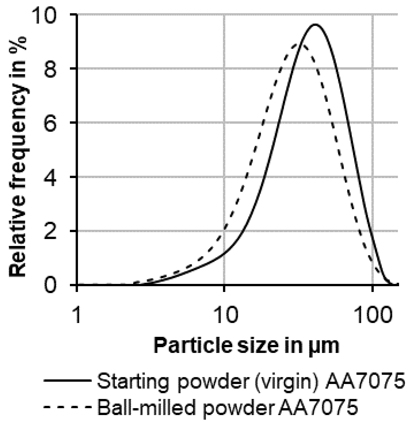
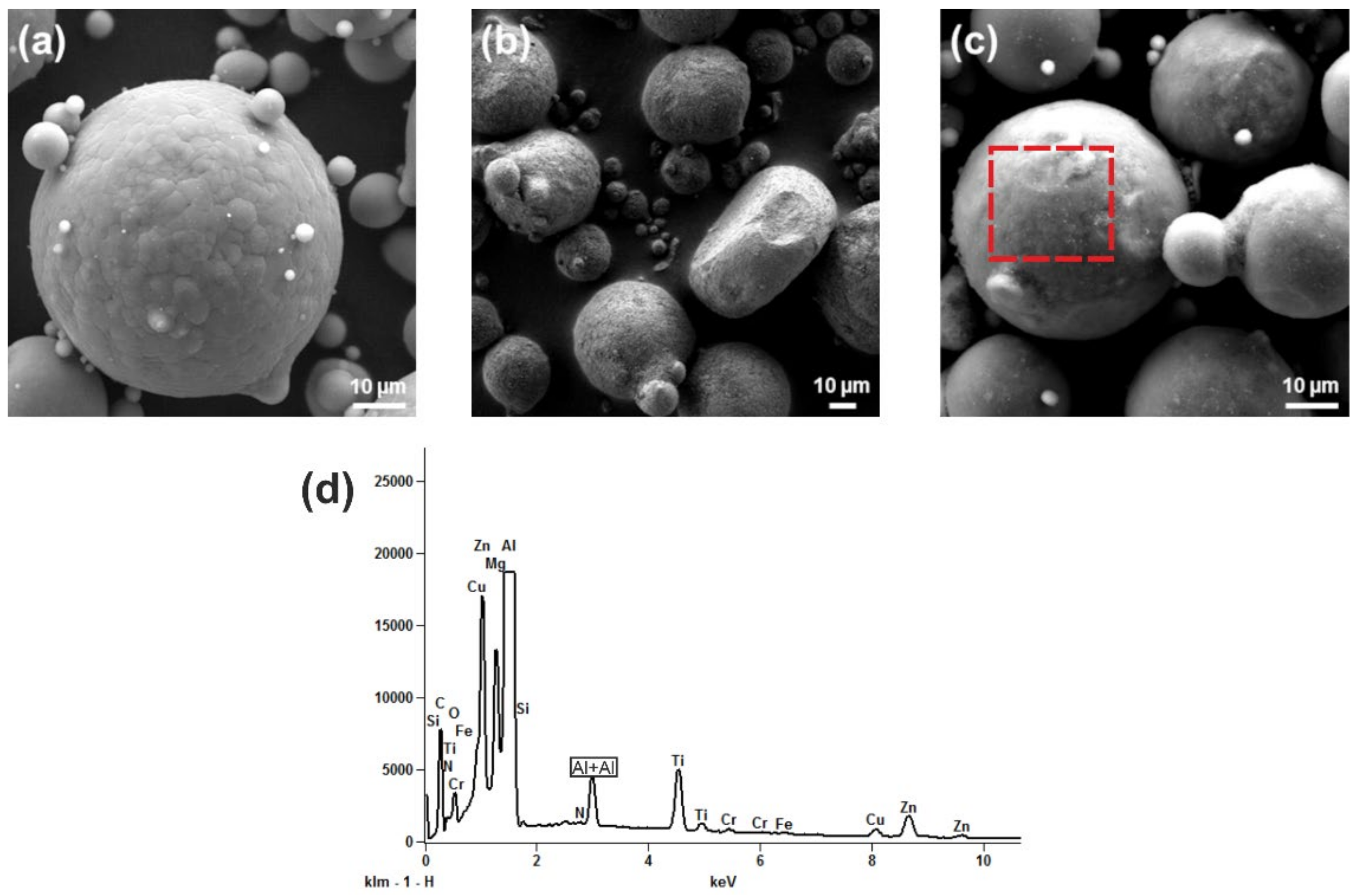
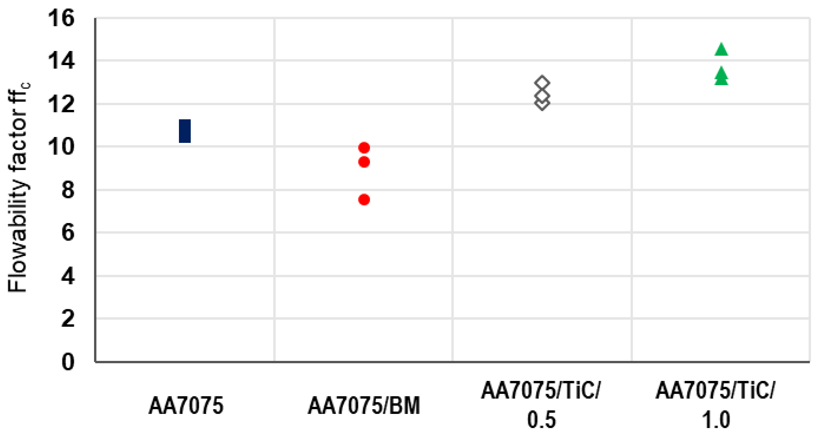
3.1. Effect of Mechanical Decoration on Powder Properties
3.2. After PBF-LB/M of Modified Powder
4. Conclusions
- ▪
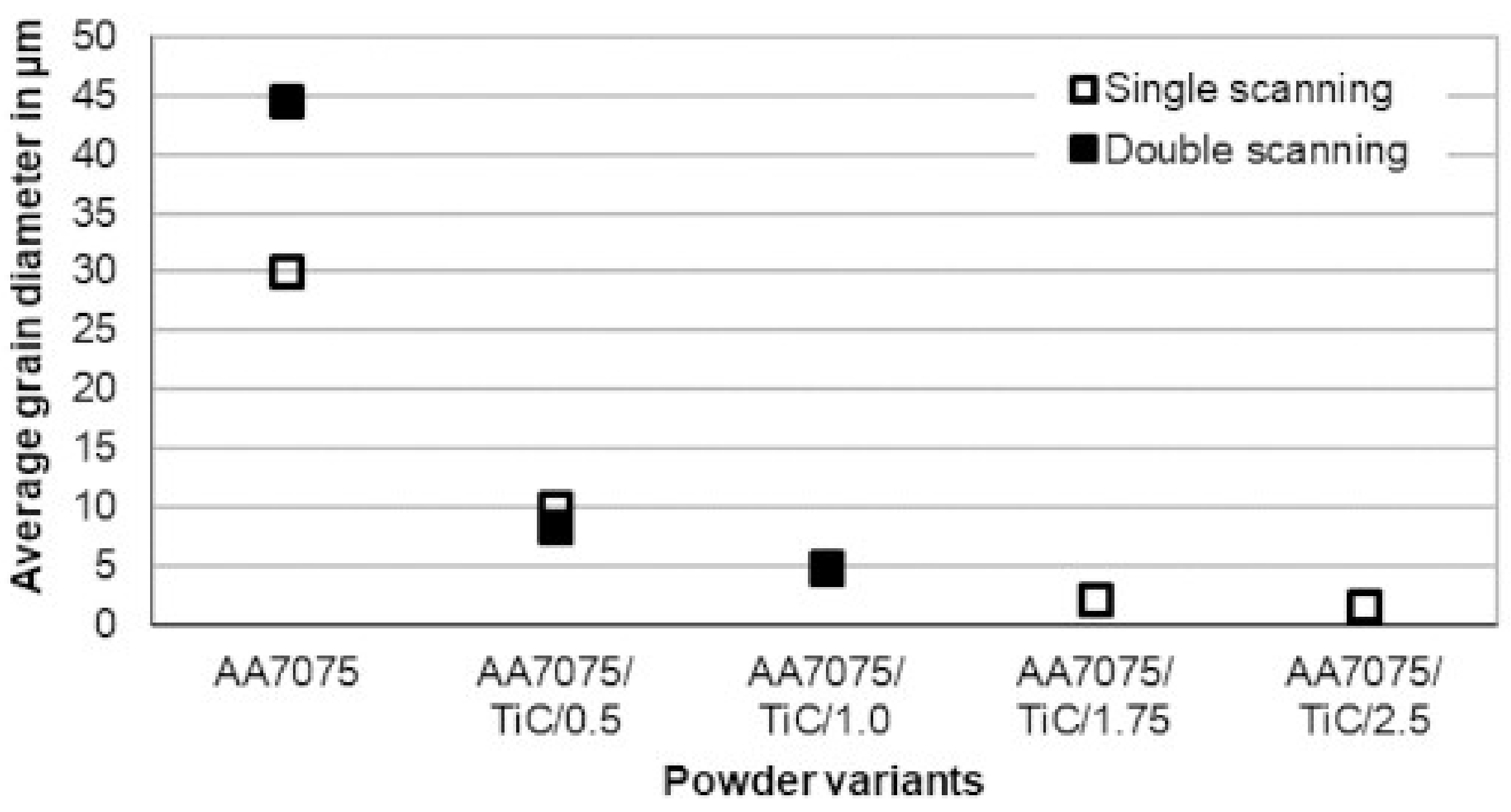
- The amount of TiC that must be added to AA7075 for significant crack reduction and crack prevention over a wide range of PBF-LB/M parameter variations must be a minimum of 1.75 ma%.
- ▪
- For modified AA7075 with TiC nanoparticles, following effects occur:
- ▪
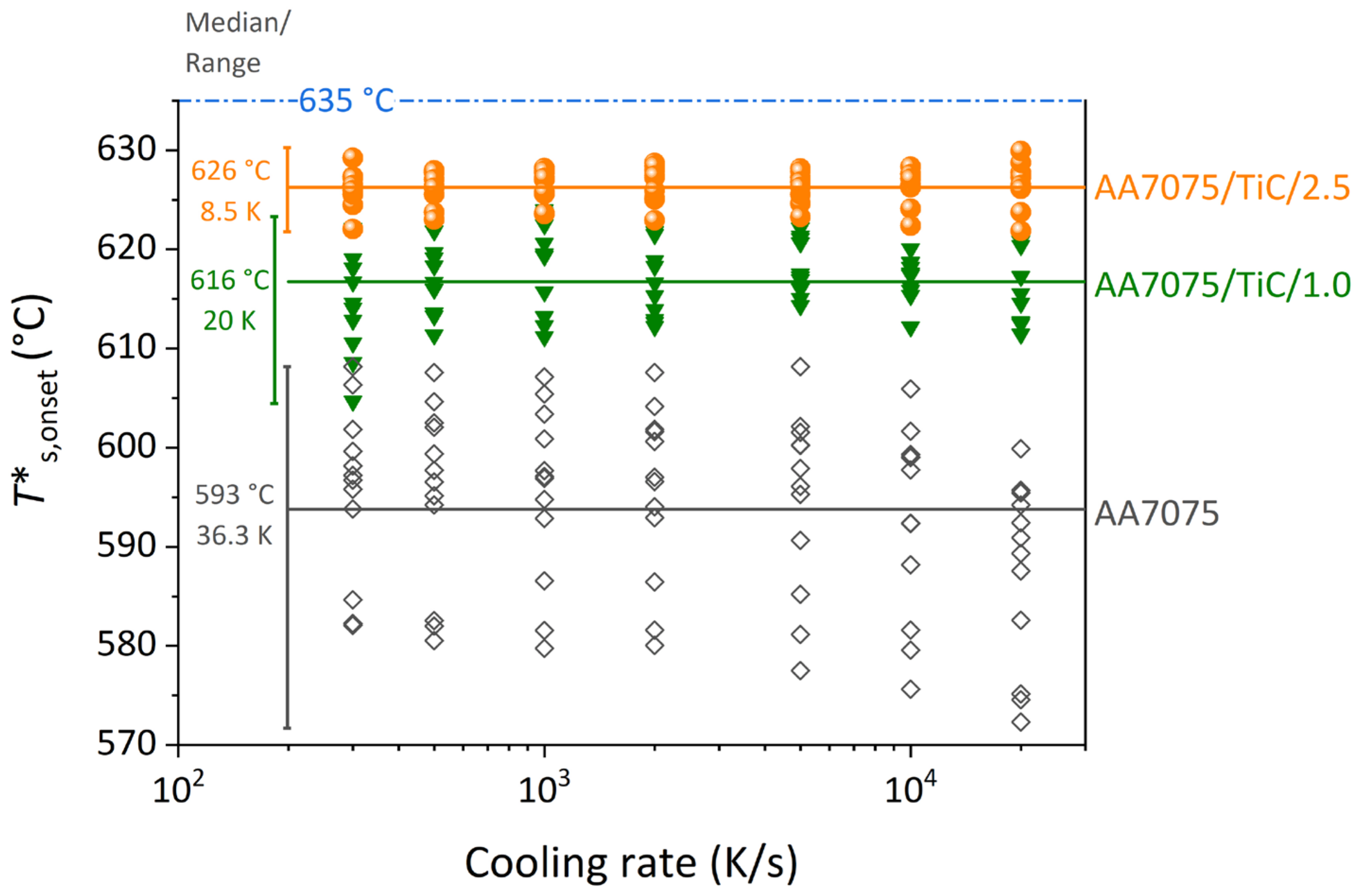
- Reduction of the solidification undercooling and its scatter.
- ▪
- Nucleation of the additional grains and substantial reduction of the resulting grain size.
- ▪
- Agglomeration of excess TiC NPs, which potentially introduce structural defects.
- ▪
- So far not specified influence on the subsequent result of heat treatment by various structures (grain size and additional nucleation sites for secondary precipitation).
- ▪
- With the addition of TiC, for each powder variation, appropriate parameter settings for the PBF-LB/M process must be applied.
- ▪
- The mechanical decoration is a suitable method in terms of:
- ▪
- Scalability industrial application.
- ▪
- Increasing the flowability of the metal powder.
- ▪
- Sufficient dispersion of TiC NPs on the powder surface and bonding between the nanoparticle and AA7075 powder particle.
Author Contributions
Funding
Data Availability Statement
Acknowledgments
Conflicts of Interest
References
- Hernández-Martínez, S.E.; Cruz-Rivera, J.J.; Garay-Reyes, C.G.; Elias-Alfaro, C.G.; Martínez-Sánchez, R.; Hernández-Rivera, J.L. Application of ball milling in the synthesis of AA 7075–ZrO2 metal matrix nanocomposite. Powder Technol. 2015, 284, 40–46. [Google Scholar] [CrossRef]
- Croteau, J.R.; Griffiths, S.; Rossell, M.D.; Leinenbach, C.; Kenel, C.; Jansen, V.; Seidman, D.N.; Dunand, D.C.; Vo, N.Q. Microstructure and mechanical properties of Al-Mg-Zr alloys processed by selective laser melting. Acta Mater. 2018, 153, 35–44. [Google Scholar] [CrossRef]
- Kusoglu, I.M.; Gökce, B.; Barcikowski, S. Research trends in laser powder bed fusion of Al alloys within the last decade. Addit. Manuf. 2020, 36, 101489. [Google Scholar] [CrossRef]
- Aversa, A.; Marchese, G.; Saboori, A.; Bassini, E.; Manfredi, D.; Biamino, S.; Ugues, D.; Fino, P.; Lombardi, M. New Aluminum Alloys Specifically Designed for Laser Powder Bed Fusion: A Review. Materials 2019, 12, 1007. [Google Scholar] [CrossRef] [Green Version]
- Aboulkhair, N.T.; Simonelli, M.; Parry, L.; Ashcroft, I.; Tuck, C.; Hague, R. 3D printing of Aluminium alloys: Additive Manufacturing of Aluminium alloys using selective laser melting. Prog. Mater. Sci. 2019, 106, 100578. [Google Scholar] [CrossRef]
- Zhang, H.; Zhu, H.; Nie, X.; Yin, J.; Hu, Z.; Zeng, X. Effect of Zirconium addition on crack, microstructure and mechanical behavior of selective laser melted Al-Cu-Mg alloy. Scr. Mater. 2017, 134, 6–10. [Google Scholar] [CrossRef]
- Louvis, E. Selective laser melting of aluminium components. J. Mater. Process. Technol. 2011, 211, 275–284. [Google Scholar] [CrossRef]
- VDI-Gesellschaft Produktion und Logistik. VDI 3405—Additive Manufacturing Processes, Rapid Manufacturing—Basics, Definitions, Processes; Beuth Verlag: Berlin, Germany, 2014; 25.020 (VDI 3405). [Google Scholar]
- DIN EN ISO/ASTM 52911-1:2020-05, Additive Manufacturing—Design—Part 1: Laser-Based Powder Bed Fusion of Metals (ISO/ASTM 52911-1:2019); German Version EN_ISO/ASTM 52911-1:2019; Beuth Verlag GmbH: Berlin, Germany, 2019.
- Kannatey-Asibu, E. Principles of Laser Materials Processing; Wiley: Hoboken, NJ, USA, 2009; ISBN 9780470459300. [Google Scholar]
- Dowd, J.D. Weld Cracking of Aluminum Alloys. Weld. J. 1952, 31, 448s–456s. [Google Scholar]
- Kou, S. Solidification and liquation cracking issues in welding. JOM 2003, 55, 37–42. [Google Scholar] [CrossRef]
- Pumphrey, W.I.; Lyons, J.V. Cracking During the Casting and Welding of the More Common Binary Aluminum Alloys. J. Inst. Met. 1948, 74, 439–455. [Google Scholar]
- Ghaini, F.M.; Sheikhi, M.; Torkamany, M.J.; Sabbaghzadeh, J. The relation between liquation and solidification cracks in pulsed laser welding of 2024 aluminium alloy. Mater. Sci. Eng. A 2009, 519, 167–171. [Google Scholar] [CrossRef]
- Wu, J.; Wang, X.Q.; Wang, W.; Attallah, M.M.; Loretto, M.H. Microstructure and strength of selectively laser melted AlSi10Mg. Acta Mater. 2016, 117, 311–320. [Google Scholar] [CrossRef] [Green Version]
- Stopyra, W.; Gruber, K.; Smolina, I.; Kurzynowski, T.; Kuźnicka, B. Laser powder bed fusion of AA7075 alloy: Influence of process parameters on porosity and hot cracking. Addit. Manuf. 2020, 35, 101270. [Google Scholar] [CrossRef]
- Kaufmann, N. Influence of process parameters on the quality of aluminium alloy EN AW 7075 using selective laser melting (SLM). Phys. Procedia 2016, 83, 918–926. [Google Scholar] [CrossRef] [Green Version]
- Murty, B.S.; Kori, S.A.; Chakraborty, M. Grain refinement of aluminium and its alloys by heterogeneous nucleation and alloying. Int. Mater. Rev. 2002, 47, 3–29. [Google Scholar] [CrossRef]
- Wang, F.; Qiu, D.; Liu, Z.-L.; Taylor, J.A.; Easton, M.A.; Zhang, M.-X. The grain refinement mechanism of cast aluminium by zirconium. Acta Mater. 2013, 61, 5636–5645. [Google Scholar] [CrossRef]
- Montero-Sistiaga, M.L. Changing the alloy composition of Al7075 for better processability by selective laser melting. J. Mater. Process. Technol. 2016, 238, 437–445. [Google Scholar] [CrossRef]
- Martin, J.H.; Yahata, B.D.; Hundley, J.M.; Mayer, J.A.; Schaedler, T.A.; Pollock, T.M. 3D printing of high-strength aluminium alloys. Nature 2017, 549, 365–369. [Google Scholar] [CrossRef] [PubMed]
- Wu, W.; Gao, C.; Liu, Z.; Wong, K.; Xiao, Z. Laser powder bed fusion of crack-free TiN/Al7075 composites with enhanced mechanical properties. Mater. Lett. 2021, 282, 128625. [Google Scholar] [CrossRef]
- Greer, A.L.; Cooper, P.S.; Meredith, M.W.; Schneider, W.; Schumacher, P.; Spittle, J.A.; Tronche, A. Grain Refinement of Aluminium Alloys by Inoculation. Adv. Eng. Mater. 2003, 5, 81–91. [Google Scholar] [CrossRef]
- Jiang, K.; Liu, X. The effect of melting temperature and time on the TiC particles. J. Alloy. Compd. 2009, 484, 95–101. [Google Scholar] [CrossRef]
- Xiang, M.; Song, M.; Zhu, Q.; Hu, C.; Yang, Y.; Lv, P.; Zhao, H.; Yun, F. Facile synthesis of high-melting point spherical TiC and TiN powders at low temperature. J. Am. Ceram. Soc. 2020, 103, 889–898. [Google Scholar] [CrossRef]
- Sokoluk, M.; Cao, C.; Pan, S.; Li, X. Nanoparticle-enabled phase control for arc welding of unweldable aluminum alloy 7075. Nat. Commun. 2019, 10, 98. [Google Scholar] [CrossRef] [PubMed] [Green Version]
- Gu, D.; Wang, H.; Chang, F.; Dai, D.; Yuan, P.; Hagedorn, Y.-C.; Meiners, W. Selective Laser Melting Additive Manufacturing of TiC/AlSi10Mg Bulk-form Nanocomposites with Tailored Microstructures and Properties. Phys. Procedia 2014, 56, 108–116. [Google Scholar] [CrossRef]
- Zhao, T.; Dahmen, M.; Cai, W.; Alkhayat, M.; Schaible, J.; Albus, P.; Zhong, C.; Hong, C.; Biermann, T.; Zhang, H.; et al. Laser metal deposition for additive manufacturing of AA5024 and nanoparticulate TiC modified AA5024 alloy composites prepared with balling milling process. Opt. Laser Technol. 2020, 131, 106438. [Google Scholar] [CrossRef]
- Lei, Z.; Bi, J.; Chen, Y.; Chen, X.; Tian, Z.; Qin, X. Effect of TiB2 content on microstructural features and hardness of TiB2/AA7075 composites manufactured by LMD. J. Manuf. Process. 2020, 53, 283–292. [Google Scholar] [CrossRef]
- Mair, P.; Goettgens, V.S.; Rainer, T.; Weinberger, N.; Letofsky-Papst, I.; Mitsche, S.; Leichtfried, G. Laser powder bed fusion of nano-CaB6 decorated 2024 aluminum alloy. J. Alloy. Compd. 2021, 863, 158714. [Google Scholar] [CrossRef]
- Zhang, H. Selective laser melting of high strength Al-Cu-Mg alloys: Processing, microstructure and mechanical properties. Mater. Sci. Eng. A 2016, 656, 47–54. [Google Scholar] [CrossRef]
- Pannitz, O.; Lüddecke, A.; Kwade, A.; Sehrt, J.T. Investigation of the in situ thermal conductivity and absorption behavior of nanocomposite powder materials in laser powder bed fusion processes. Mater. Des. 2021, 201, 109530. [Google Scholar] [CrossRef]
- Zhou, L.; Pan, H.; Hyer, H.; Park, S.; Bai, Y.; McWilliams, B.; Cho, K.; Sohn, Y. Microstructure and tensile property of a novel AlZnMgScZr alloy additively manufactured by gas atomization and laser powder bed fusion. Scr. Mater. 2019, 158, 24–28. [Google Scholar] [CrossRef]
- Gao, C.; Xiao, Z.; Liu, Z.; Zhu, Q.; Zhang, W. Selective laser melting of nano-TiN modified AlSi10Mg composite powder with low laser reflectivity. Mater. Lett. 2019, 236, 362–365. [Google Scholar] [CrossRef]
- Brüggemann, J.-P.; Risse, L.; Kullmer, G.; Richard, H.A. Optimization of the fracture mechanical properties of additively manufactured EN AW-7075. Procedia Struct. Integr. 2018, 13, 311–316. [Google Scholar] [CrossRef]
- Tan, H.; Hao, D.; Al-Hamdani, K.; Zhang, F.; Xu, Z.; Clare, A.T. Direct metal deposition of TiB2/AlSi10Mg composites using satellited powders. Mater. Lett. 2018, 214, 123–126. [Google Scholar] [CrossRef]
- Clare, A.; Kennedy, A. Additive Manufacturing. Available online: https://patents.google.com/patent/WO2015036802A3/en (accessed on 15 November 2021).
- Lüddecke, A.; Pannitz, O.; Zetzener, H.; Sehrt, J.T.; Kwade, A. Powder properties and flowability measurements of tailored nanocomposites for powder bed fusion applications. Mater. Des. 2021, 202, 109536. [Google Scholar] [CrossRef]
- DIN EN 573-3:2019-10, Aluminium und Aluminiumlegierungen—Chemische Zusammensetzung und Form von Halbzeug—Teil_3: Chemische Zusammensetzung und Erzeugnisformen; Deutsche Fassung EN_573-3:2019; Beuth Verlag GmbH: Berlin, Germany, 2019. (In German)
- Mertens, R.; Dadbakhsh, S.; van Humbeeck, J.; Kruth, J.-P. Application of base plate preheating during selective laser melting. Procedia CIRP 2018, 74, 5–11. [Google Scholar] [CrossRef]
- Brüggemann, J.-P.; Riemer, A.; Reschetnik, W.; Aydinöz, M.E.; Kullmer, A.; Richard, H.A.; Schaper, M. Optimierung von Fahrradtretkurbeln mittels additiver Fertigung. In DVM-Bericht 401, Arbeitskreis: Additiv Gefertigte Bauteile und Strukturen; Deutscher Verband für Materialforschung und-prüfung eV Berlin: Berlin, Germany, 2016; pp. 101–112. (In German) [Google Scholar]
- Mezger, T.G. 5. Auflage, revidierte Ausgabe. In Das Rheologie Handbuch: Für Anwender von Rotations- und Oszillations-Rheometern; Vincentz Network: Hannover, Germany, 2016; ISBN 3-86630-632-6. (In German) [Google Scholar]
- Zhuravlev, E.; Milkereit, B.; Yang, B.; Heiland, S.; Vieth, P.; Voigt, M.; Schaper, M.; Grundmeier, G.; Schick, C.; Kessler, O. Assessment of AlZnMgCu alloy powder modification for crack-free laser powder bed fusion by differential fast scanning calorimetry. Mater. Des. 2021, 204, 109677. [Google Scholar] [CrossRef]
- Damon, J.; Koch, R.; Kaiser, D.; Graf, G.; Dietrich, S.; Schulze, V. Process development and impact of intrinsic heat treatment on the mechanical performance of selective laser melted AISI 4140. Addit. Manuf. 2019, 28, 275–284. [Google Scholar] [CrossRef]
- DIN EN ISO 643:2020-06, Stahl_- Mikrophotographische Bestimmung der Erkennbaren Korngröße (ISO_643:2019, Korrigierte Fassung 2020-03); Deutsche Fassung ISO_643:2020; Beuth Verlag GmbH: Berlin, Germany, 2020. (In German)
- Sun, S.; Liu, P.; Hu, J.; Hong, C.; Qiao, X.; Liu, S.; Zhang, R.; Wu, C. Effect of solid solution plus double aging on microstructural characterization of 7075 Al alloys fabricated by selective laser melting (SLM). Opt. Laser Technol. 2019, 114, 158–163. [Google Scholar] [CrossRef]
- Jenike, A.W. Storage and flow of solids. Bull. No. 123 1976, 53, 22–32. Available online: https://digital.library.unt.edu/ark:/67531/metadc1067072/ (accessed on 13 November 2021).
- Spierings, A.B.; Voegtlin, M.; Bauer, T.; Wegener, K. Powder flowability characterisation methodology for powder-bed-based metal additive manufacturing. Prog. Addit. Manuf. 2016, 1, 9–20. [Google Scholar] [CrossRef] [Green Version]
- Aluminum 7075-T6; 7075-T651. Available online: http://www.matweb.com/search/DataSheet.aspx?MatGUID=4f19a42be94546b686bbf43f79c51b7d&ckck=1 (accessed on 1 October 2020).
- Hu, Z.; Qi, Y.; Nie, X.; Zhang, H.; Zhu, H. The Portevin-Le Chatelier (PLC) effect in an Al-Cu aluminum alloy fabricated by selective laser melting. Mater. Charact. 2021, 178, 111198. [Google Scholar] [CrossRef]


| Material | Elemental Composition in ma% | ||||||
|---|---|---|---|---|---|---|---|
| Al | Zn | Mg | Cu | Si | Fe | Ti | |
| AA7075 | 91.70 | 5.04 | 1.26 | 1.46 | 0.05 | 0.11 | 0.03 |
| Powder Variant | Undercooling [ΔTU] in K | Scatter in K |
|---|---|---|
| AA7075 | 42 | 36 |
| AA7075/TiC/0.5 | 14 [43] | 11 [43] |
| AA7075/TiC/1.0 | 19 | 20 |
| AA7075/TiC/2.5 | 9 | 9 |
| Origin | Condition | Elemental Composition in ma% | ||||||
|---|---|---|---|---|---|---|---|---|
| Al | Zn | Mg | Cu | Si | Ti | |||
| Powder modification and preparation for PBF-LB/M | AA7075/TiC/1.0 | Modified | 90.60 | 5.07 | 1.29 | 1.50 | 0.06 | 1.03 |
| SI | 90.60 | 5.10 | 1.20 | 1.47 | 0.07 | 0.99 | ||
| VD | 90.40 | 5.18 | 1.28 | 1.47 | 0.10 | 1.05 | ||
| After PBF-LB/M | AA7075/TiC/1.0 | CP | 94.40 | 1.21 | 1.13 | 1.51 | 0.12 | 1.21 |
| OP | 94.40 | 1.36 | 1.00 | 1.46 | 0.11 | 1.55 | ||
| BS | 91.30 | 3.85 | 1.35 | 1.57 | 0.28 | 0.77 | ||
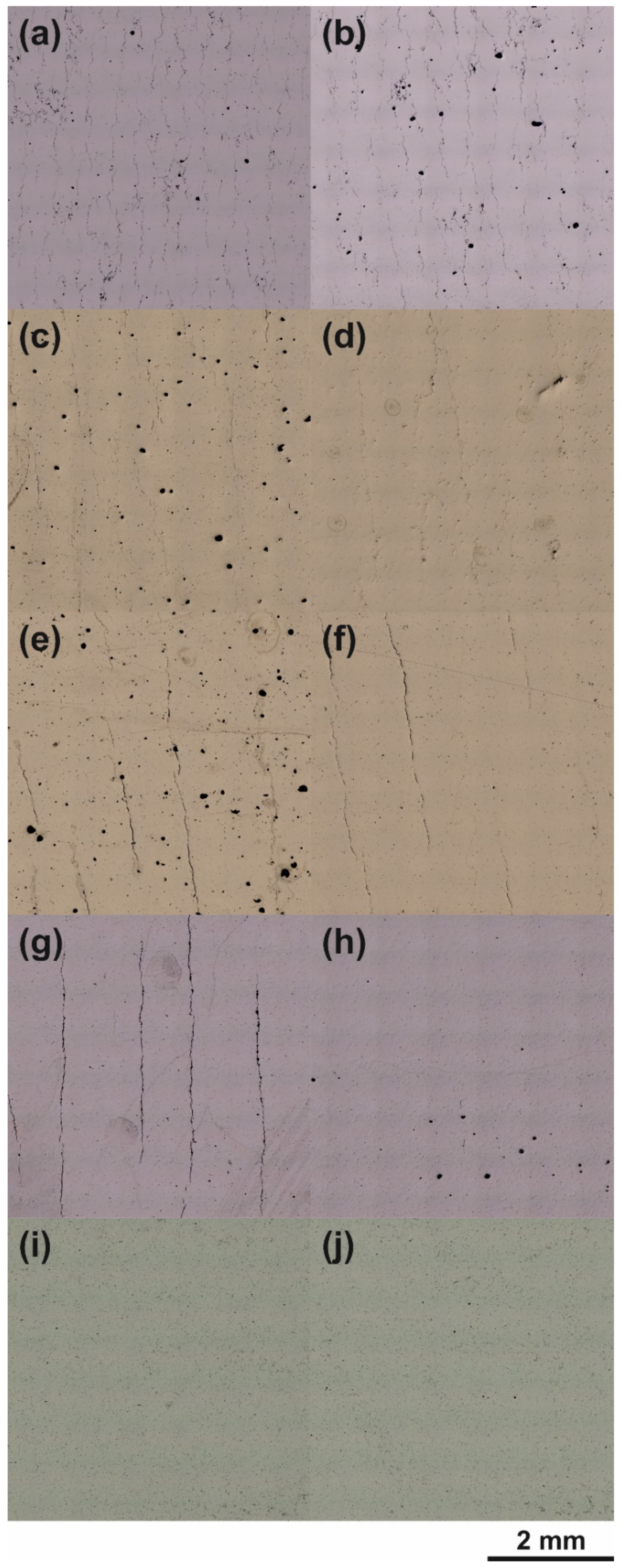
| No | Powder Variant | Figure | Laser Power [PL] in W | Scan Speed [vs] in m/s | Hatch Distance [hd] in mm | Volumetric Energy Input [EV] in J/mm3 | Relative Part Density in % | Crack Density in Cracks/cm2 * | Remark |
|---|---|---|---|---|---|---|---|---|---|
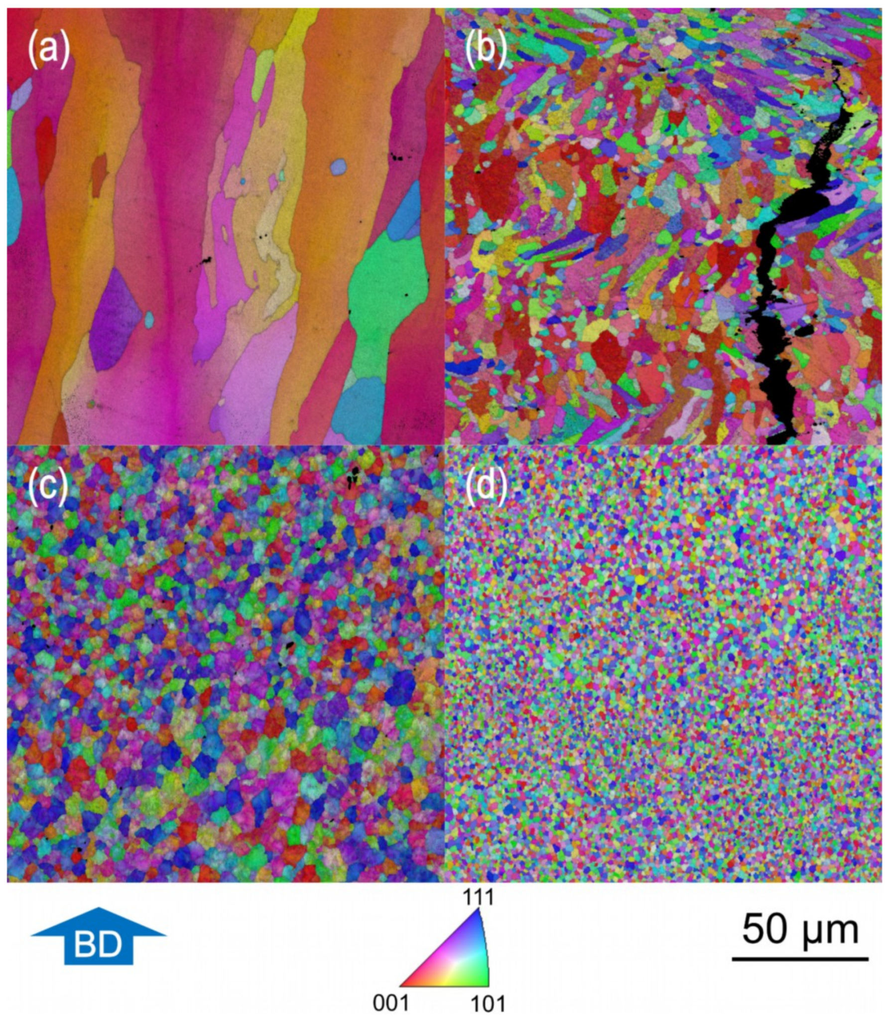
| 1 | AA7075 | Figure 7a | 370 | 900 | 0.08 | 102.8 | 99.50 | 154 | Single-exposed |
| 2 | 7075/TiC/0.5 | Figure 7b | 370 | 900 | 0.08 | 102.8 | - | - | Single-exposed |
| 3 | 7075/TiC/1.0 | Figure 7c | 370 | 900 | 0.08 | 102.8 | 99.33 | 2 | Double-exposed |
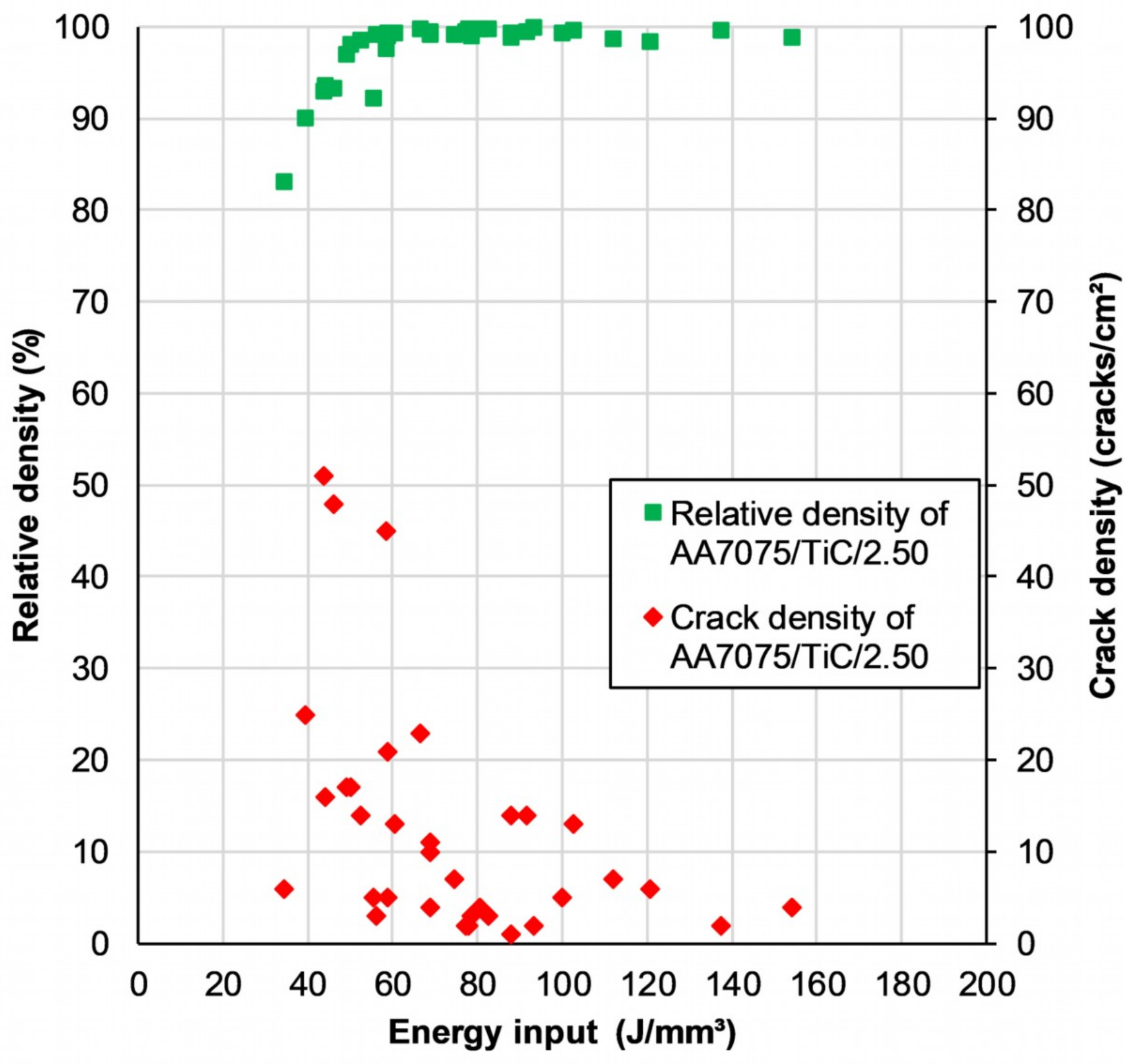
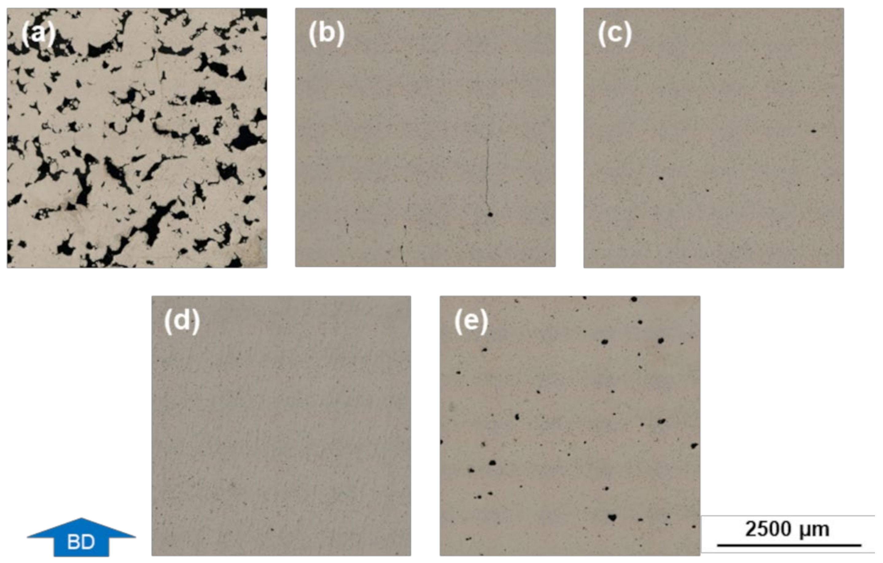
| 4 | 7075/TiC/2.5 | Figure 6a | 290 | 1200 | 0.14 | 34.5 | 83.1 | 6 | Lowest EV in the parameter study |
| 5 | 7075/TiC/2.5 | Figure 6b | 350 | 1050 | 0.10 | 66.7 ** | 99.8 | 23 | |
| 6 | 7075/TiC/2.5 | Figure 6c | 290 | 600 | 0.14 | 69.0 | 99.4 | 10 | |
| 7 | 7075/TiC/2.5 | Figure 6d and Figure 7d | 350 | 750 | 0.10 | 93.3 | 99.9 | 2 | Parameter setting to achieve the highest density for material variation AA7075/TiC/2.5 |
| 8 | 7075/TiC/2.5 | Figure 6e | 370 | 600 | 0.08 | 154.2 | 98.8 | 4 | Highest EV in the parameter study |
Publisher’s Note: MDPI stays neutral with regard to jurisdictional claims in published maps and institutional affiliations. |
© 2021 by the authors. Licensee MDPI, Basel, Switzerland. This article is an open access article distributed under the terms and conditions of the Creative Commons Attribution (CC BY) license (https://creativecommons.org/licenses/by/4.0/).
Share and Cite
Heiland, S.; Milkereit, B.; Hoyer, K.-P.; Zhuravlev, E.; Kessler, O.; Schaper, M. Requirements for Processing High-Strength AlZnMgCu Alloys with PBF-LB/M to Achieve Crack-Free and Dense Parts. Materials 2021, 14, 7190. https://doi.org/10.3390/ma14237190
Heiland S, Milkereit B, Hoyer K-P, Zhuravlev E, Kessler O, Schaper M. Requirements for Processing High-Strength AlZnMgCu Alloys with PBF-LB/M to Achieve Crack-Free and Dense Parts. Materials. 2021; 14(23):7190. https://doi.org/10.3390/ma14237190
Chicago/Turabian StyleHeiland, Steffen, Benjamin Milkereit, Kay-Peter Hoyer, Evgeny Zhuravlev, Olaf Kessler, and Mirko Schaper. 2021. "Requirements for Processing High-Strength AlZnMgCu Alloys with PBF-LB/M to Achieve Crack-Free and Dense Parts" Materials 14, no. 23: 7190. https://doi.org/10.3390/ma14237190