
Influence of Impurities on the Front Velocity of Sputter Deposited Al/CuO Thermite Multilayers


Abstract
:1. Introduction
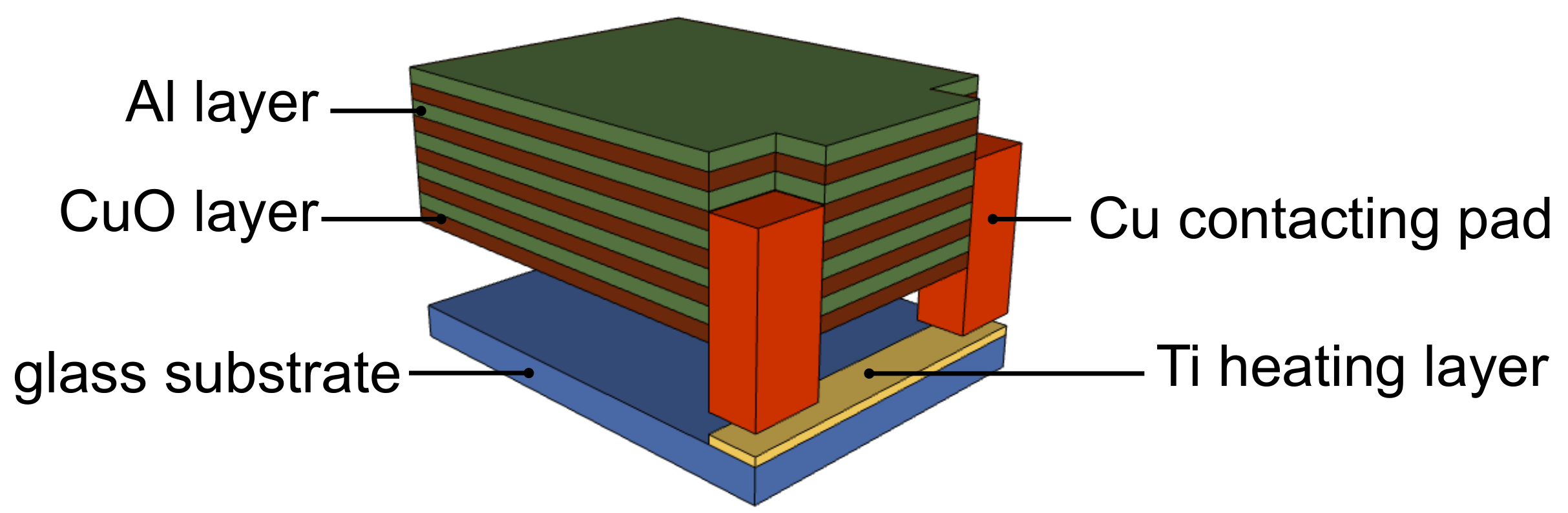
2. Experimental
3. Results
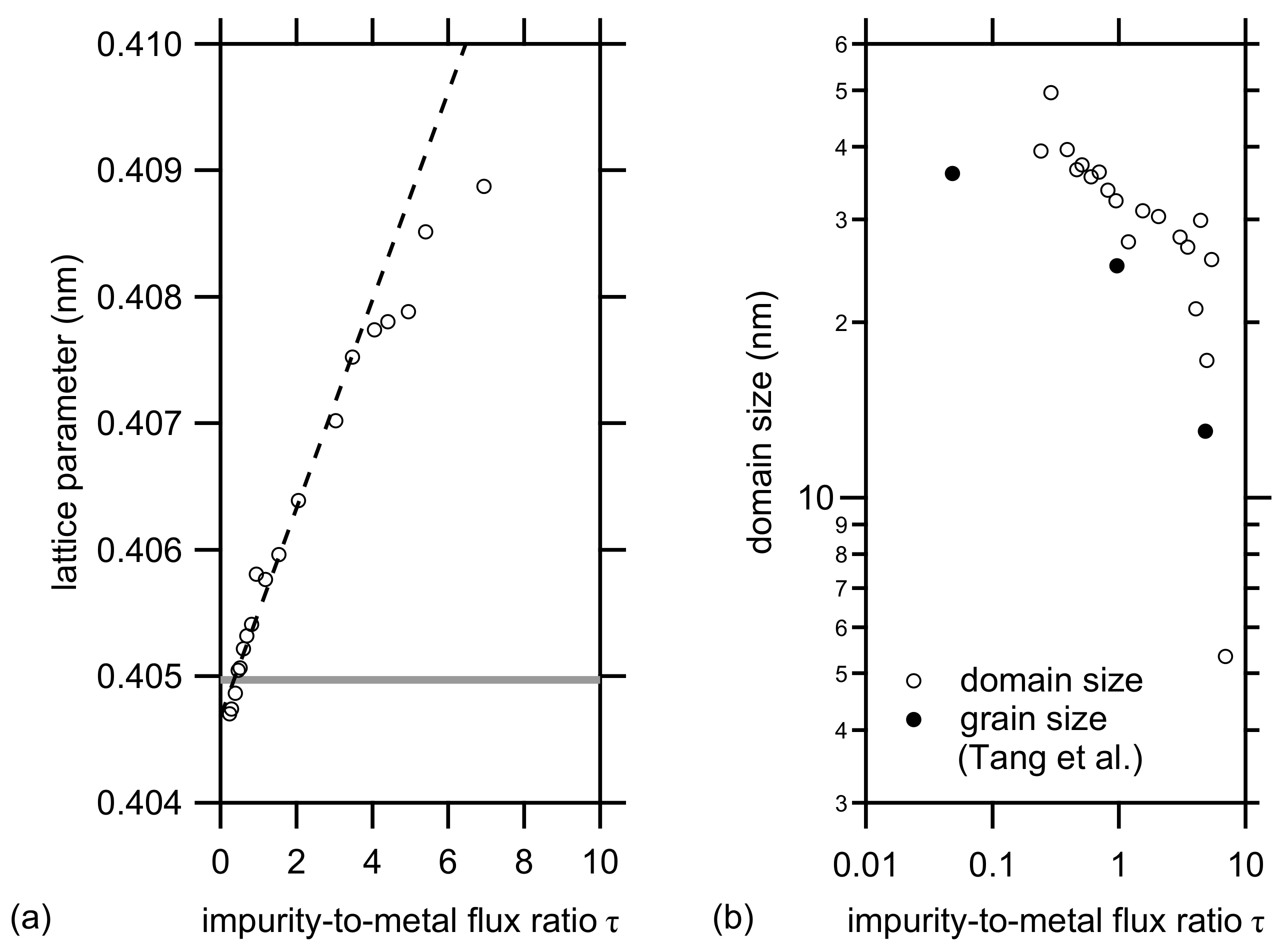
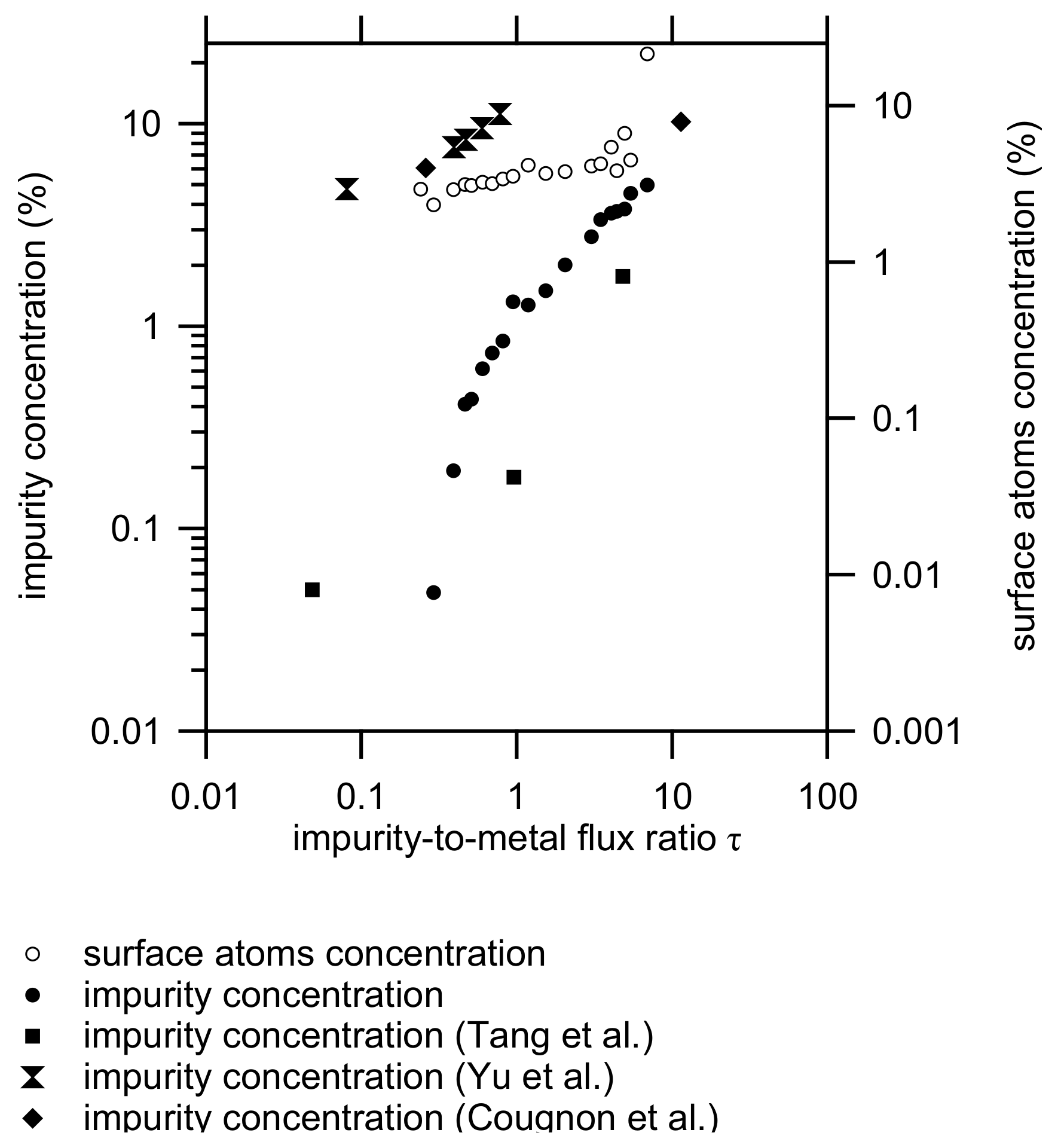
3.1. XRD Analysis
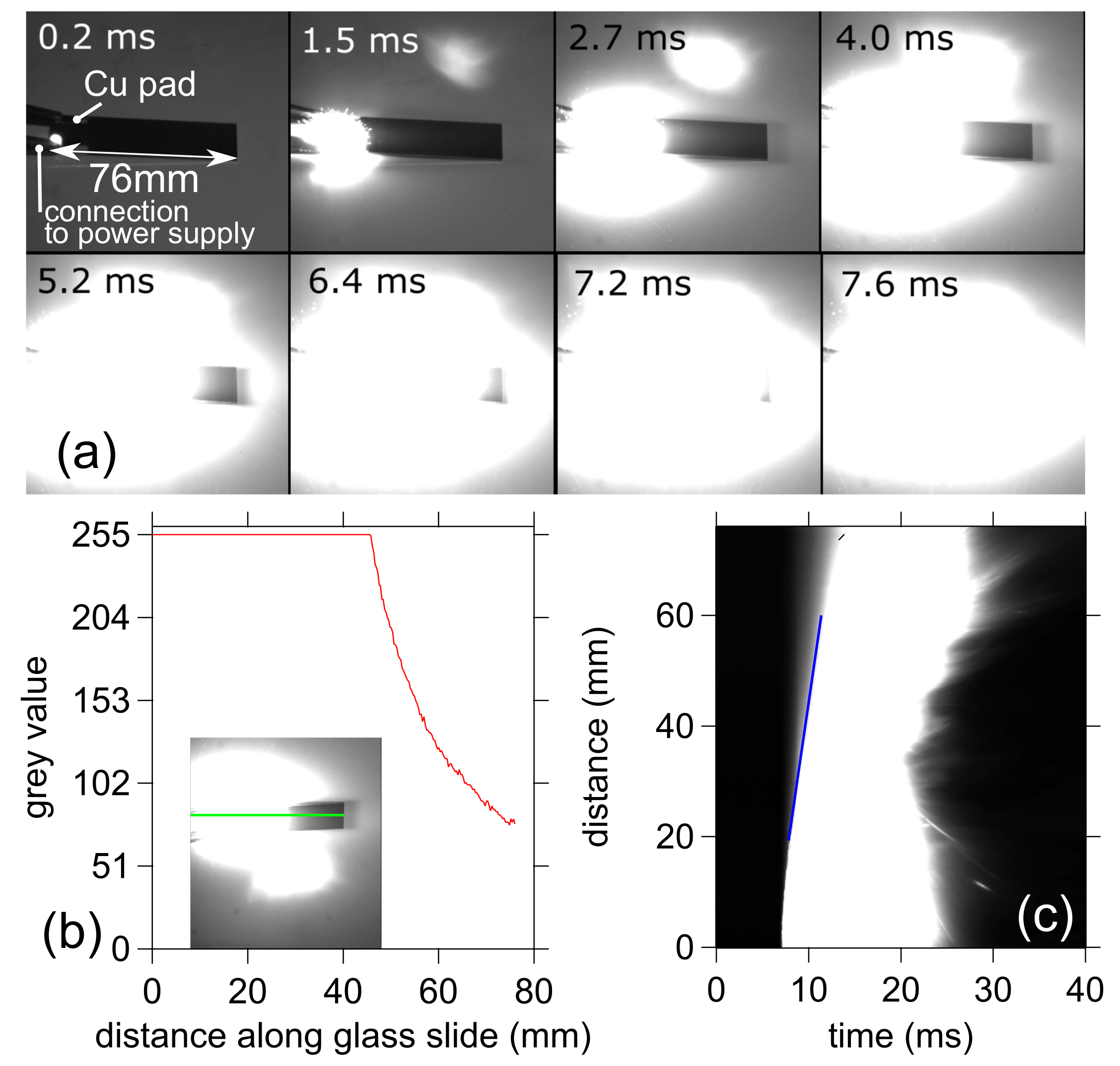
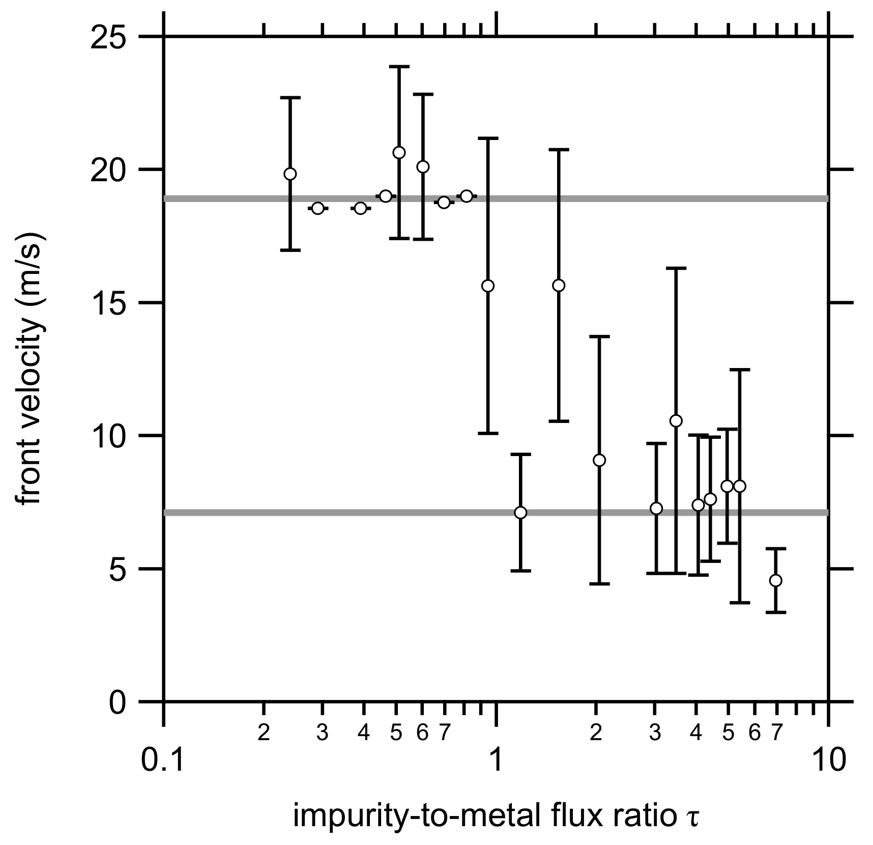
3.2. Front Velocity Measurements
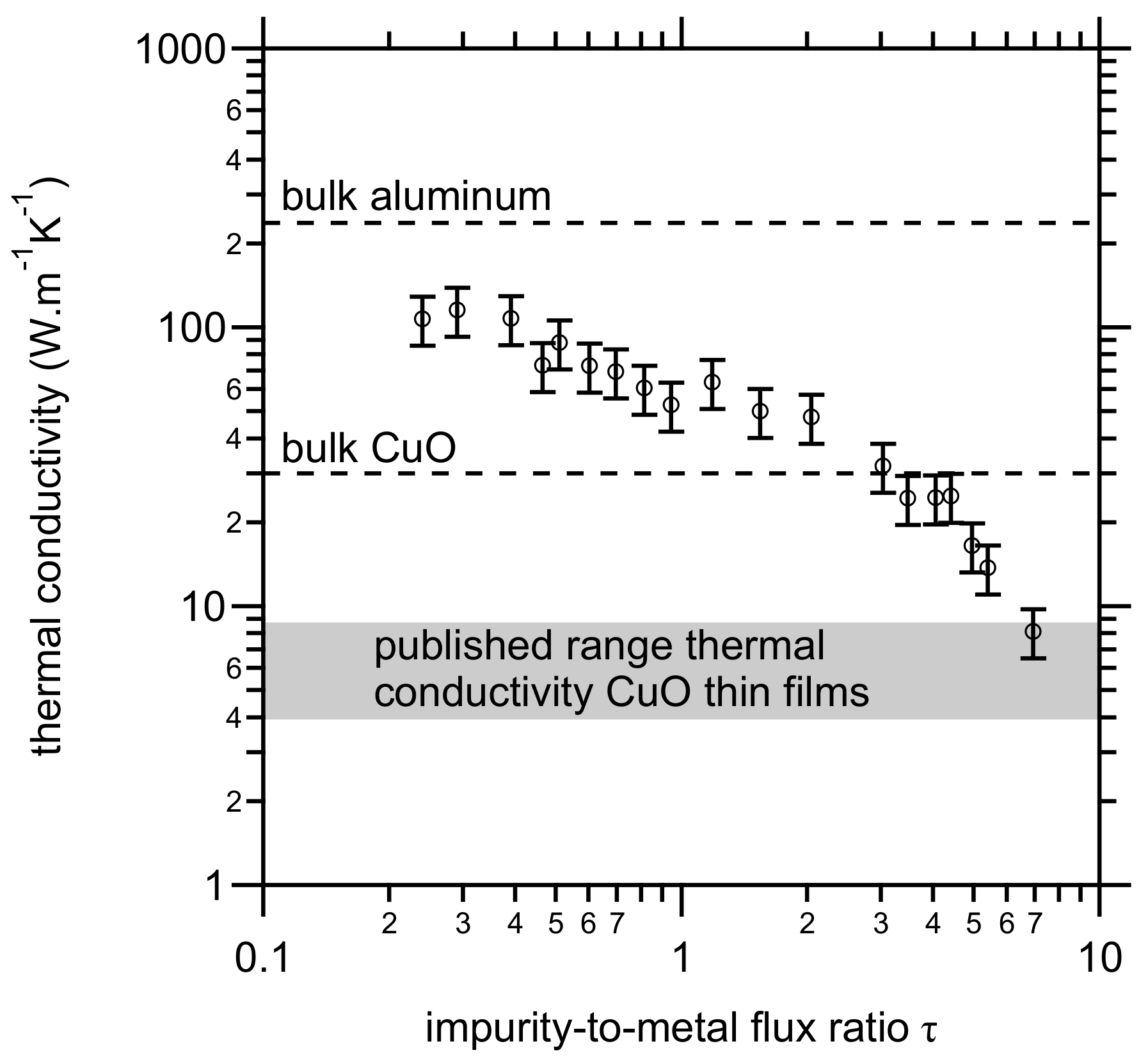
3.3. Thermal Conductivity
4. Discussion
5. Conclusions
Author Contributions
Funding
Institutional Review Board Statement
Informed Consent Statement
Data Availability Statement
Acknowledgments
Conflicts of Interest
References
- Mariello, M.; Guido, F.; Mastronardi, V.M.; Madaro, F.; Mehdipour, I.; Todaro, M.T.; Rizzi, F.; Vittorio, M.D. Micro- and nanodevices for wind energy harvesting. In Nano Tools and Devices for Enhanced Renewable Energy; Elsevier: Amsterdam, The Netherlands, 2021; pp. 291–374. [Google Scholar] [CrossRef]
- Silva, J.P.B.; Sekhar, K.C.; Pan, H.; MacManus-Driscoll, J.L.; Pereira, M. Advances in Dielectric Thin Films for Energy Storage Applications, Revealing the Promise of Group IV Binary Oxides. ACS Energy Lett. 2021, 6, 2208–2217. [Google Scholar] [CrossRef]
- Rossi, C.; Zhang, K.; Esteve, D.; Alphonse, P.; Tailhades, P.; Vahlas, C. Nanoenergetic materials for MEMS: A review. J. Microelectromech. Syst. 2007, 16, 919–931. [Google Scholar] [CrossRef] [Green Version]
- Adams, D.P. Reactive multilayers fabricated by vapor deposition: A critical review. Thin Solid Films 2015, 576, 98–128. [Google Scholar] [CrossRef] [Green Version]
- Weihs, T.P. Fabrication and characterization of reactive multilayer films and foils. In Metallic Films for Electronic, Optical and Magnetic Applications; Elsevier: Amsterdam, The Netherlands, 2014; pp. 160–243. [Google Scholar] [CrossRef]
- Goldschmidt, H.; Vautin, C. Aluminium as a heating and reducing agent. J. Soc. Chem. Ind. 1898, 6, 543–545. [Google Scholar]
- Salvagnac, L.; Assie-Souleille, S.; Rossi, C. Layered Al/CuO thin films for tunable ignition and actuations. Nanomaterials 2020, 10, 2009. [Google Scholar] [CrossRef]
- Fischer, S.H.; Grubelich, M.C. Theoretical Energy Release of Thermites, Intermetallics, and Combustible Metals; Technical Report; Sandia National Lab. (SNL-NM): Albuquerque, NM, USA, 1998. [Google Scholar] [CrossRef] [Green Version]
- Rossi, C. Engineering of Al/CuO reactive multilayer thin films for tunable initiation and actuation. Propellants Explos. Pyrotech. 2018, 44, 94–108. [Google Scholar] [CrossRef] [Green Version]
- Nicollet, A.; Lahiner, G.; Belisario, A.; Souleille, S.; Djafari-Rouhani, M.; Estève, A.; Rossi, C. Investigation of Al/CuO multilayered thermite ignition. J. Appl. Phys. 2017, 121, 034503. [Google Scholar] [CrossRef] [Green Version]
- Manesh, N.A.; Basu, S.; Kumar, R. Experimental flame speed in multi-layered nano-energetic materials. Combust. Flame 2010, 157, 476–480. [Google Scholar] [CrossRef]
- Amini-Manesh, N.; Basu, S.; Kumar, R. Modeling of a reacting nanofilm on a composite substrate. Energy 2011, 36, 1688–1697. [Google Scholar] [CrossRef]
- Lahiner, G.; Nicollet, A.; Zapata, J.; Marín, L.; Richard, N.; Rouhani, M.D.; Rossi, C.; Estève, A. A diffusion–reaction scheme for modeling ignition and self-propagating reactions in Al/CuO multilayered thin films. J. Appl. Phys. 2017, 122, 155105. [Google Scholar] [CrossRef]
- Bahrami, M.; Taton, G.; Conédéra, V.; Salvagnac, L.; Tenailleau, C.; Alphonse, P.; Rossi, C. Magnetron sputtered Al-CuO nanolaminates: Effect of stoichiometry and layers thickness on energy release and burning rate. Propellants Explos. Pyrotech. 2014, 39, 365–373. [Google Scholar] [CrossRef]
- Petrantoni, M.; Rossi, C.; Salvagnac, L.; Conédéra, V.; Estève, A.; Tenailleau, C.; Alphonse, P.; Chabal, Y.J. Multilayered Al/CuO thermite formation by reactive magnetron sputtering: Nano versus micro. J. Appl. Phys. 2010, 108, 084323. [Google Scholar] [CrossRef] [Green Version]
- Zapata, J.; Nicollet, A.; Julien, B.; Lahiner, G.; Esteve, A.; Rossi, C. Self-propagating combustion of sputter-deposited Al/CuO nanolaminates. Combust. Flame 2019, 205, 389–396. [Google Scholar] [CrossRef] [Green Version]
- Dulmaa, A.; Vrielinck, H.; Khelifi, S.; Depla, D. Sputter deposition of copper oxide films. Appl. Surf. Sci. 2019, 492, 711–717. [Google Scholar] [CrossRef]
- Dulmaa, A.; Cougnon, F.G.; Dedoncker, R.; Depla, D. On the grain size-thickness correlation for thin films. Acta Mater. 2021, 212, 116896. [Google Scholar] [CrossRef]
- Cougnon, F.G.; Dulmaa, A.; Dedoncker, R.; Galbadrakh, R.; Depla, D. Impurity dominated thin film growth. Appl. Phys. Lett. 2018, 112, 221903. [Google Scholar] [CrossRef] [Green Version]
- Weismiller, M.; Malchi, J.; Yetter, R.; Foley, T. Dependence of flame propagation on pressure and pressurizing gas for an Al/CuO nanoscale thermite. Proc. Combust. Inst. 2009, 32, 1895–1903. [Google Scholar] [CrossRef]
- Sullivan, K.T.; Kuntz, J.D.; Gash, A.E. The Role of Fuel Particle Size on Flame Propagation Velocity in Thermites with a Nanoscale Oxidizer. Propellants Explos. Pyrotech. 2014, 39, 407–415. [Google Scholar] [CrossRef]
- Nakashima, P.N.H. The crystallography of aluminum and its alloys. In Encyclopedia of Aluminum and Its Alloys; CRC Press: Boca Raton, FL, USA, 2019. [Google Scholar] [CrossRef] [Green Version]
- Tang, F.; Gianola, D.S.; Moody, M.P.; Hemker, K.J.; Cairney, J.M. Observations of grain boundary impurities in nanocrystalline Al and their influence on microstructural stability and mechanical behaviour. Acta Mater. 2012, 60, 1038–1047. [Google Scholar] [CrossRef]
- Linnera, J.; Sansone, G.; Maschio, L.; Karttunen, A.J. Thermoelectric properties of p-type Cu2O, CuO, and NiO from hybrid density functional theory. J. Phys. Chem. C 2018, 122, 15180–15189. [Google Scholar] [CrossRef]
- Lide, R.L. (Ed.) CRC Handbook of Chemistry and Physics, Internet Version 2005; CRC Press: Boca Raton, FL, USA, 2005. [Google Scholar]
- Chen, Y.Y.; Juang, J.Y. Finite element analysis and equivalent parallel-resistance model for conductive multilayer thin films. Meas. Sci. Technol. 2016, 27, 074006. [Google Scholar] [CrossRef]
- Wei-Gang, M.; Wang, H.D.; Xing, Z.; Koji, T. Different effects of grain boundary scattering on charge and heat transport in polycrystalline platinum and gold nanofilms. Chin. Phys. B 2009, 18, 2035–2040. [Google Scholar] [CrossRef]
- Gall, D. Electron mean free path in elemental metals. J. Appl. Phys. 2016, 119, 085101. [Google Scholar] [CrossRef] [Green Version]
- Schmidt, A.J.; Cheaito, R.; Chiesa, M. Characterization of thin metal films via frequency-domain thermoreflectance. J. Appl. Phys. 2010, 107, 024908. [Google Scholar] [CrossRef] [Green Version]
- Boiko, B.T.; Pugachev, A.T.; Bratsychin, V.M. Method for the determination of the thermophysical properties of evaporated thin films. Thin Solid Films 1973, 17, 157–161. [Google Scholar] [CrossRef]
- Lugo, J.M.; Oliva, A.I. Thermal properties of metallic films at room conditions by the heating slope. J. Thermophys. Heat Transf. 2016, 30, 452–460. [Google Scholar] [CrossRef]
- Abolghasemi, M.; Keshavarz, A.; Mehrabian, M.A. Thermodynamic analysis of a thermal storage unit under the influence of nano-particles added to the phase change material and/or the working fluid. Heat Mass Transf. 2012, 48, 1961–1970. [Google Scholar] [CrossRef]
- Ahmed, M.; Yusoff, M.; Ng, K.; Shuaib, N. Effect of corrugation profile on the thermal–hydraulic performance of corrugated channels using CuO–water nanofluid. Case Stud. Therm. Eng. 2014, 4, 65–75. [Google Scholar] [CrossRef] [Green Version]
- Kim, H.; Ham, J.; Park, C.; Cho, H. Theoretical investigation of the efficiency of a U-tube solar collector using various nanofluids. Energy 2016, 94, 497–507. [Google Scholar] [CrossRef]
- Jegadheeswaran, S.; Sundaramahalingam, A.; Pohekar, S.D. High-conductivity nanomaterials for enhancing thermal performance of latent heat thermal energy storage systems. J. Therm. Anal. Calorim. 2019, 138, 1137–1166. [Google Scholar] [CrossRef]
- Desmukh, K.B.; Karmare, S.V. A review on convective heat augmentation techniques in solar thermal collector using nanofluid. J. Therm. Eng. 2021, 1257–1266. [Google Scholar] [CrossRef]
- Gmelin, E. Cupric oxide-CuO: Its structural, electrical, thermal and magnetic properties. Indian J. Pure Appl. Phys. 1992, 30, 596–608. [Google Scholar]
- Kusiak, A.; Battaglia, J.L.; Gomez, S.; Manaud, J.P.; Lepetitcorps, Y. CuO thin films thermal conductivity and interfacial thermal resistance estimation. Eur. Phys. J. Appl. Phys. 2006, 35, 17–27. [Google Scholar] [CrossRef]
- Ntifiez Regueiro, M.; Castello, D.; Jaime, M. Thermal conducitivity of high temperature superconductors. Physica B 1991, 169, 631–632. [Google Scholar] [CrossRef]
- Liu, M.; Lin, M.C.; Wang, C. Enhancements of thermal conductivities with Cu, CuO, and carbon nanotube nanofluids and application of MWNT/water nanofluid on a water chiller system. Nanoscale Res. Lett. 2011, 6, 297. [Google Scholar] [CrossRef] [Green Version]
- Yoshida, N.; Naito, T.; Fujishiro, H. Thermoelectric Properties of Li-Doped CuO. Jpn. J. Appl. Phys. 2013, 52, 031102. [Google Scholar] [CrossRef]
- Hartung, D.; Gather, F.; Hering, P.; Kandzia, C.; Reppin, D.; Polity, A.; Meyer, B.K.; Klar, P.J. Assessing the thermoelectric properties of CuxO (x = 1 to 2) thin films as a function of composition. Appl. Phys. Lett. 2015, 106, 253901. [Google Scholar] [CrossRef]
- Armstrong, R. Models for gasless combustion in layered materials and random media. Combust. Sci. Technol. 1990, 71, 155–174. [Google Scholar] [CrossRef]
- Tichtchenko, E.; Estève, A.; Rossi, C. Modeling the self-propagation reaction in heterogeneous and dense media: Application to Al/CuO thermite. Combust. Flame 2021, 228, 173–183. [Google Scholar] [CrossRef]
- Gianola, D.S.; Van Petegem, S.; Legros, M.; Brandstetter, S.; Van Swygenhoven, H.; Hemker, K.J. Stress-assisted discontinuous grain growth and its effect on the deformation behavior of nanocrystalline aluminum thin films. Acta Mater. 2006, 54, 2253–2263. [Google Scholar] [CrossRef]
- Yu, H.Z.; Thompson, C.V. Stress engineering using low oxygen background pressures during Volmer-Weber growth of polycrystalline nickel films. J. Vac. Sci. Technol. A Vac. Surf. Films 2015, 33, 021504. [Google Scholar] [CrossRef]
- Cougnon, F.G.; Schramm, I.C.; Depla, D. On the electrical properties of sputter deposited thin films: The role of energy and impurity flux. Thin Solid Films 2019, 690, 137540. [Google Scholar] [CrossRef]
- Winkler, A.; Rendulic, K.D.; Wendl, K. Quantitative measurement of the sticking coefficient for oxygen on nickel. Appl. Surf. Sci. 1983, 14, 209–220. [Google Scholar] [CrossRef]
- Brune, H.; Wintterlin, J.; Trost, J.; Ertl, G.; Wiechers, J.; Behm, R.J. Interaction of oxygen with Al(111) studied by scanning tunneling microscopy. J. Chem. Phys. 1993, 99, 2128–2148. [Google Scholar] [CrossRef] [Green Version]
- Leroy, W.P.; Mahieu, S.; Persoons, R.; Depla, D. Method to determine the sticking coefficient of O2 on deposited Al during reactive magnetron sputtering using mass spectrometry. Plasma Process. Polym. 2009, 6, S342–S346. [Google Scholar] [CrossRef]
- Alawieh, L.; Knio, O.M.; Weihs, T.P. Effect of thermal properties on self-propagating fronts in reactive nanolaminates. J. Appl. Phys. 2011, 110, 013509. [Google Scholar] [CrossRef]
- Yu, J.; Tang, Z.; Zhang, F.; Ding, H.; Huang, Z. Measurement of the heat capacity of copper thin films using a micropulse calorimeter. J. Heat Transf. 2009, 132, 012403. [Google Scholar] [CrossRef]
- Jayaraman, S.; Mann, A.B.; Reiss, M.; Weihs, T.P.; Knio, O.M. Numerical study of the effect of heat losses on self-propagating reactions in multilayer foils. Combust. Flame 2001, 124, 178–194. [Google Scholar] [CrossRef]
- Agrawal, D.C. Introduction to Nanoscience and Nanomaterials; World Scientific: Singapore, 2013. [Google Scholar] [CrossRef] [Green Version]
- Lilensten, L.; B. Gault, B. New approach for FIB-preparation of atom probe specimens for aluminum alloys. PLoS ONE 2020, 15, e0231179. [Google Scholar] [CrossRef]
- Zweiacker, K. In-situ TEM Investigation of Rapid Solidification of Aluminum and Aluminum Copper Alloys. Ph.D. Thesis, University of Pittsburgh, Pittsburgh, PA, USA, 2015. [Google Scholar]
- Iyer, S.S.; Wong, C.Y. Grain growth study in aluminum films and electromigration implications. J. Appl. Phys. 1985, 57, 4594–4598. [Google Scholar] [CrossRef]
- Barna, P.B.; Adamik, M. Fundamental structure forming phenomena of polycrystalline films and the structure zone models. Thin Solid Films 1998, 317, 27–33. [Google Scholar] [CrossRef]
- Petrov, I.; Barna, P.B.; Hultman, L.; Greene, J.E. Microstructural evolution during film growth. J. Vac. Sci. Technol. A Vac. Surf. Films 2003, 21, S117–S128. [Google Scholar] [CrossRef]
- Koike, J.; S. Utsunomiya, S.; Y. Shimoyama, Y.; K. Maruyama, K.; Oikawa, H. Thermal cycling fatigue and deformation mechanism in aluminum alloy thin films on silicon. J. Mater. Res. 1998, 13, 3256–3264. [Google Scholar] [CrossRef]
- Lumpp, J.K.; Chen, N.; Goretta, K.C. Mechanical properties of CuO. High Temp. Mater. Process. 1990, 9, 1–6. [Google Scholar] [CrossRef]

| Parameter | Ti | Al | CuO |
|---|---|---|---|
| Target material | Ti | Al | Cu |
| Argon pressure (Pa) | 0.8 | 0.5 | 0.5 |
| Oxygen fraction | 0 | 0 | 0.28 |
| Discharge current (A) | 0.7 | 0.5 | 0.3 |
| Target-to-substrate distance T-S (cm) | 7 | 10 | 10 |
| Layer thickness (nm) | 400 | 100 | 100 |
| Deposition rate (nm/s) | 0.91 | 0.83 | 1.25 |
Publisher’s Note: MDPI stays neutral with regard to jurisdictional claims in published maps and institutional affiliations. |
© 2021 by the authors. Licensee MDPI, Basel, Switzerland. This article is an open access article distributed under the terms and conditions of the Creative Commons Attribution (CC BY) license (https://creativecommons.org/licenses/by/4.0/).
Share and Cite
Dulmaa, A.; Depla, D. Influence of Impurities on the Front Velocity of Sputter Deposited Al/CuO Thermite Multilayers. Materials 2021, 14, 7224. https://doi.org/10.3390/ma14237224
Dulmaa A, Depla D. Influence of Impurities on the Front Velocity of Sputter Deposited Al/CuO Thermite Multilayers. Materials. 2021; 14(23):7224. https://doi.org/10.3390/ma14237224
Chicago/Turabian StyleDulmaa, Altangerel, and Diederik Depla. 2021. "Influence of Impurities on the Front Velocity of Sputter Deposited Al/CuO Thermite Multilayers" Materials 14, no. 23: 7224. https://doi.org/10.3390/ma14237224
APA StyleDulmaa, A., & Depla, D. (2021). Influence of Impurities on the Front Velocity of Sputter Deposited Al/CuO Thermite Multilayers. Materials, 14(23), 7224. https://doi.org/10.3390/ma14237224