
Impact of Preparation of Titanium Alloys on Their Abrasive Water Jet Machining

Abstract
:1. Introduction
2. Experimental Setup
3. Results
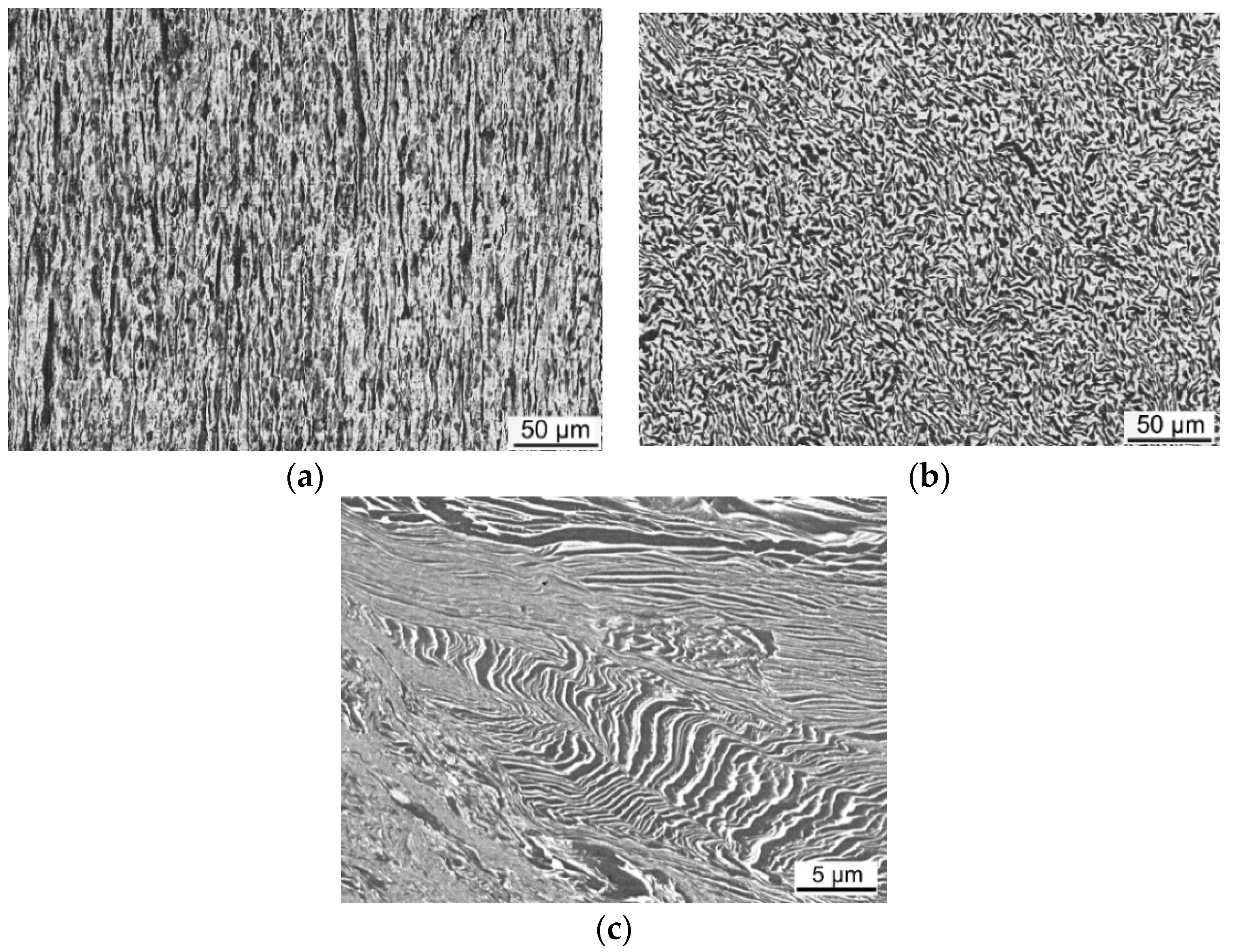
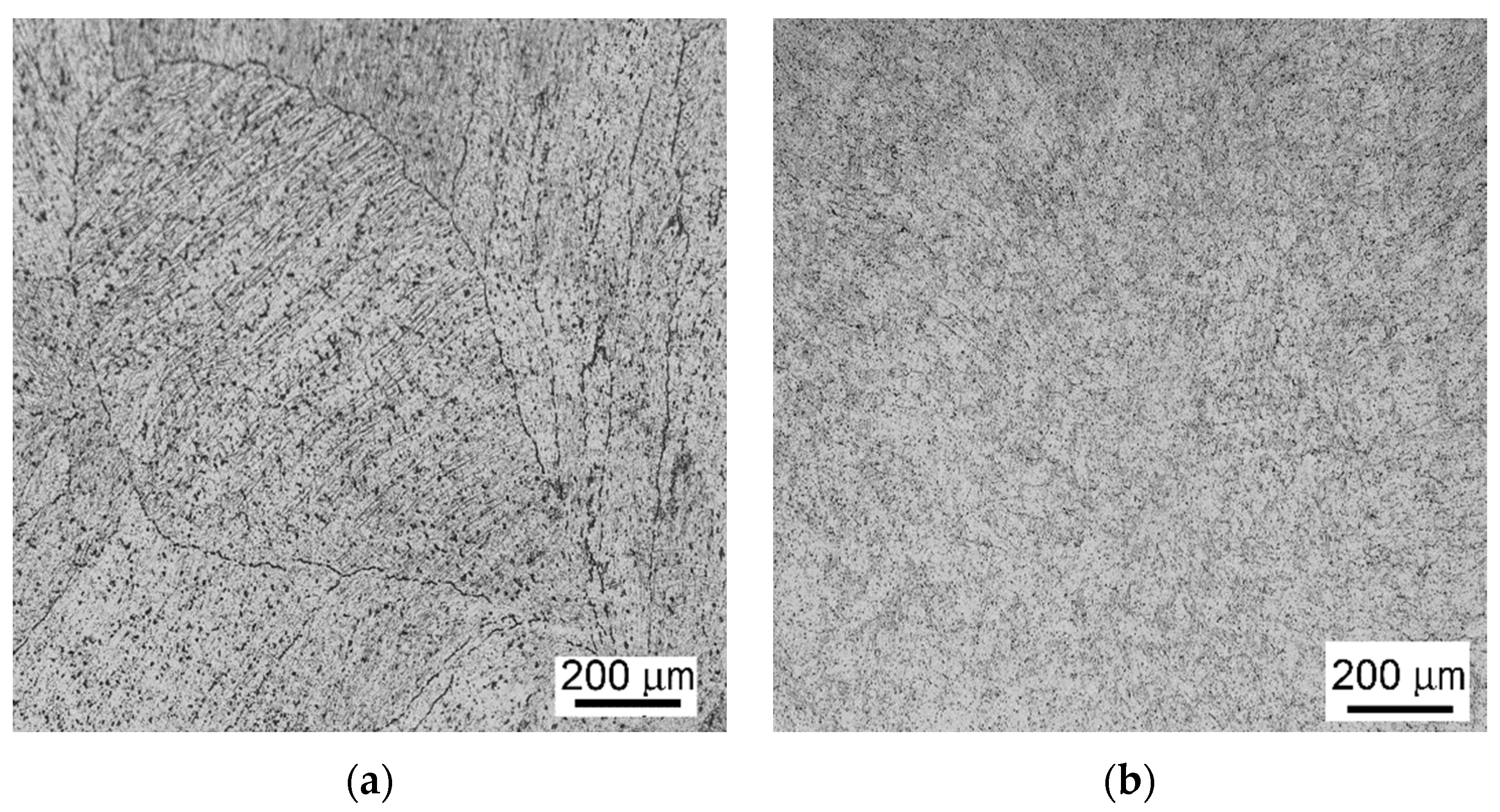
3.1. Microstructural Observations
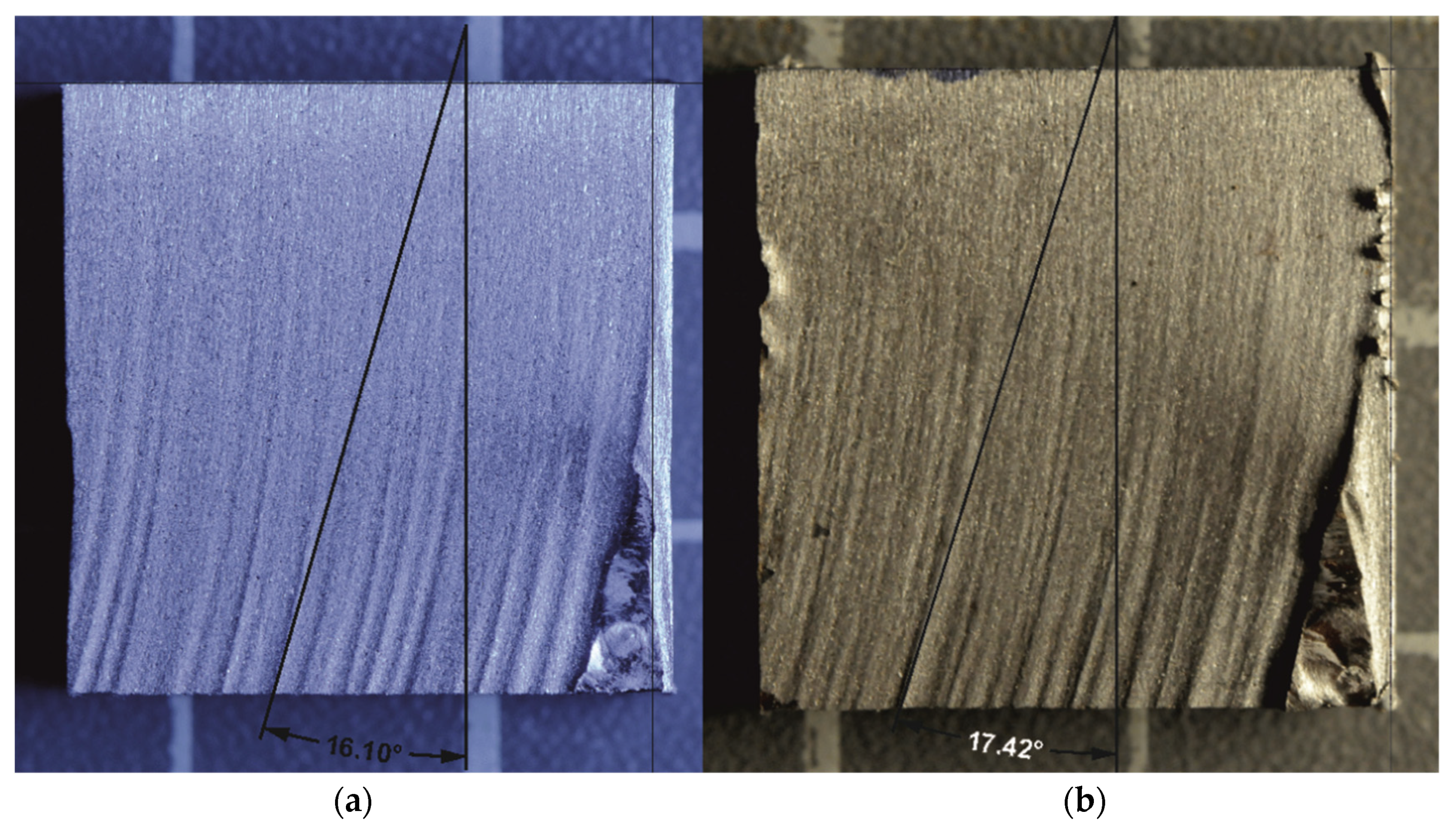
3.2. Declination Angles
4. Discussion
5. Conclusions
Author Contributions
Funding
Institutional Review Board Statement
Informed Consent Statement
Data Availability Statement
Acknowledgments
Conflicts of Interest
References
- Russell, K.L. Lee. Structure-Property Relations in Nonferrous Metals, 1st ed.; John Wiley & Sons, Inc.: Hoboken, NJ, USA, 2005. [Google Scholar]
- Lutjering, G.; Williams, J.C. Titanium; Springer: Berlin, Germany, 2003. [Google Scholar]
- Greger, M.; Kocich, R.; Kander, L.; Jonsta, P. Nanostructured titanium for dental applications. In Proceedings of the Metal 2010 19th International Conference on Metallurgy and Materials, Roznov pod Radhostem, Czech Republic, 18–20 May 2010; Tanger Ltd: Ostrava, Czech Republic, 2010; pp. 182–186. [Google Scholar]
- Zach, L.; Kunčická, L.; Růžička, P.; Kocich, R. Design analysis and verification of a knee joint oncological prosthesis finite element model. Comput. Biol. Med. 2014, 54, 53–60. [Google Scholar] [CrossRef]
- Rishi, P.; Ramulu, M. Abrasive water jet machining of titanium (Ti6Al4V)–CFRP stacks—A semianalytical modeling approach in the prediction of kerf geometry. J. Manuf. Process. 2019, 39, 327–337. [Google Scholar]
- Kunčická, L.; Kocich, R.; Lowe, T.C. Advances in metals and alloys for joint replacement. Prog. Mater. Sci. 2017, 88, 232–280. [Google Scholar] [CrossRef]
- Nocivin, A.; Raducanu, D.; Vasile, B.; Trisca-Rusu, C.; Cojocaru, E.; Dan, A.; Irimescu, R.; Cojocaru, V. Tailoring a low young modulus for a beta titanium alloy by combining severe plastic deformation with solution treatment. Materials 2021, 14, 3467. [Google Scholar] [CrossRef]
- Ozaltin, K.; Chrominski, W.; Kulczyk, M.; Panigrahi, A.; Horky, J.; Zehetbauer, M.; Lewandowska, M. Enhancement of mechanical properties of biocompatible Ti–45Nb alloy by hydrostatic extrusion. J. Mater. Sci. 2014, 49, 6930–6936. [Google Scholar] [CrossRef] [Green Version]
- Wang, Z.; Chen, J.; Besnard, C.; Kunčická, L.; Kocich, R.; Korsunsky, A.M. In situ neutron diffraction investigation of texture-dependent Shape Memory Effect in a near equiatomic NiTi alloy. Acta Mater. 2021, 202, 135–148. [Google Scholar] [CrossRef]
- Greger, M.; Kocich, R.; Černý, M.; Kander, L. Properties of comercial pure titanium after equal channel angular pressing. In Proceedings of the Metal 2009 18th International Conference on Metallurgy and Materials, Hradec and Moravici, Czech Republic, 19–21 May 2009; Tanger Ltd: Ostrava, Czech Republic, 2009; pp. 516–520. [Google Scholar]
- An, B.; Li, Z.; Diao, X.; Xin, H.; Zhang, Q.; Jia, X.; Wu, Y.; Li, K.; Guo, Y. In vitro and in vivo studies of ultrafine-grain Ti as dental implant material processed by ECAP. Mater. Sci. Eng. C 2016, 67, 34–41. [Google Scholar] [CrossRef]
- Zhao, P.C.; Yuan, G.J.; Wang, R.Z.; Guan, B.; Jia, Y.F.; Zhang, X.C.; Tu, S.T. Grain-refining and strengthening mechanisms of bulk ultrafine grained CP-Ti processed by L-ECAP and MDF. J. Mater. Sci. Technol. 2021, 83, 196–207. [Google Scholar] [CrossRef]
- Kocich, R.; Macháčková, A.; Andreyachshenko, V.A. A study of plastic deformation behaviour of Ti alloy during equal channel angular pressing with partial back pressure. Comput. Mater. Sci. 2015, 101, 233–241. [Google Scholar] [CrossRef]
- Kunčická, L.; Kocich, R.; Drápala, J. Andreyachshenko, V. FEM simulations and comparison of the ecap and ECAP-PBP influence on Ti6Al4V alloy’s deformation behaviour. In Proceedings of the Metal 2013 22nd International Conference on Metallurgy and Materials, Brno, Czech Republic, 15–17 May 2013; Tanger Ltd: Ostrava, Czech Republic, 2013; pp. 391–396. [Google Scholar]
- Kocich, R.; Kursa, M.; Szurman, I.; Dlouhý, A. The influence of imposed strain on the development of microstructure and transformation characteristics of Ni–Ti shape memory alloys. J. Alloys Compd. 2011, 509, 2716–2722. [Google Scholar] [CrossRef]
- Kocich, R.; Szurman, I.; Kursa, M.; Fiala, J. Fiala. Investigation of influence of preparation and heat treatment on deformation behaviour of the alloy NiTi after ECAE. Mater. Sci. Eng. A 2009, 512, 100–104. [Google Scholar] [CrossRef]
- Sheremetyev, V.; Churakova, A.; Derkach, M.; Gunderov, D.; Raab, G.; Prokoshkin, S. Effect of ECAP and annealing on structure and mechanical properties of metastable beta Ti-18Zr-15Nb (at.%) alloy. Mater. Lett. 2021, 305, 130760. [Google Scholar] [CrossRef]
- Lin, Z.; Wang, L.; Xue, X.; Lu, W.; Qin, J.; Zhang, D. Microstructure evolution and mechanical properties of a Ti–35Nb–3Zr–2Ta biomedical alloy processed by equal channel angular pressing (ECAP). Mater. Sci. Eng. C 2013, 33, 4551–4561. [Google Scholar] [CrossRef] [PubMed]
- Gupta, R.K.; Kumar, V.A.; Gururaja, U.V.; Subramani, K.; Prakash, U.; Chakravarthi, K.V.A.; Ramkumar, P.; Sarkar, P. Solution treatment and aging (STA) study of thick-wall ring from Titanium alloy Ti6Al4V. Met. Sci. Heat Treat. 2015, 717, 47. [Google Scholar]
- Gupta, R.K.; Kumar, V.A.; Chhangani, S. Study on variants of solution treatment and aging cycle of titanium alloy Ti6Al4V. J. Mater. Eng. Perform. 2016, 25, 1492–1501. [Google Scholar] [CrossRef]
- Ezugwu, E.O.; Wang, Z.M. Titanium alloys and their machinability—A review. J. Mater. Process. Technol. 1997, 68, 262–274. [Google Scholar] [CrossRef]
- Yuan, Y.; Chen, J.; Gao, H.; Wang, X. An investigation into the abrasive waterjet milling circular pocket on titanium alloy. Int. J. Adv. Manuf. Technol. 2020, 107, 4503–4515. [Google Scholar] [CrossRef]
- Hlaváč, L.M.; Gembalová, L.; Štěpán, P.; Hlaváčová, I.M. Improvement of abrasive water jet machining accuracy for titanium and TiNb alloy. Int. J. Adv. Manuf. Technol. 2015, 80, 1733–1740. [Google Scholar] [CrossRef]
- Shipway, P.H.; Fowler, G.; Pashby, I.R. Characteristics of the surface of a titanium alloy following milling with abrasive waterjets. Wear 2005, 258, 123–132. [Google Scholar] [CrossRef]
- Fowler, G.; Shipway, P.H.; Pashby, I.R. A technical note on grit embedment following abrasive water-jet milling of a titanium alloy. J. Mater. Process. Technol. 2005, 159, 356–368. [Google Scholar] [CrossRef]
- Fowler, G.; Shipway, P.H.; Pashby, I.R. Abrasive water-jet controlled depth milling of Ti6Al4V alloy—An investigation of the role of jet-workpiece traverse speed and abrasive grit size on the characteristics of the milled material. J. Mater. Process. Technol. 2005, 161, 407–414. [Google Scholar] [CrossRef]
- Fowler, G.; Pashby, I.R.; Shipway, P.H. The effect of particle hardness and shape when abrasive water jet milling of titanium alloy Ti6Al4V. Wear 2009, 266, 613–620. [Google Scholar] [CrossRef]
- Arola, D.; McCain, M.L.; Kunaporn, S.; Ramulu, M. Waterjet and abrasive waterjet surface treatment of titanium: A comparison of surface texture and residual stress. Wear 2001, 249, 943–950. [Google Scholar] [CrossRef]
- Arola, D.; Alade, A.E.; Weber, W. Improving fatigue strength of metals using abrasive waterjet peening. Mach. Sci. Technol. 2006, 10, 197–218. [Google Scholar] [CrossRef]
- Hashish, M. A modeling study of metal-cutting with abrasive waterjets. J. Eng. Mater. Technol. 1984, 106, 88–100. [Google Scholar] [CrossRef]
- Hashish, M. A model for abrasive-waterjet (AWJ) machining. J. Eng. Mater. Technol. 1989, 111, 154–162. [Google Scholar] [CrossRef]
- Bitter, J.G.A. A study of erosion phenomena part 1. Wear 1963, 6, 5–21. [Google Scholar] [CrossRef]
- Bitter, J.G.A. A study of erosion phenomena part 2. Wear 1963, 6, 169–190. [Google Scholar] [CrossRef]
- Sheldon, G.L.; Finnie, I. On the ductile behavior of nominally brittle materials during erosive cutting. ASME J. Eng. Ind. 1966, 88, 387–392. [Google Scholar] [CrossRef]
- Sheldon, G.L.; Finnie, I. The mechanism of material removal in the erosive cutting of brittle materials. ASME J. Eng. Ind. 1966, 88, 393–399. [Google Scholar] [CrossRef]
- Hlaváč, L.; Hlaváčová, I.; Gembalová, L.; Kaličinský, J.; Fabián, S.; Měšťánek, J.; Kmec, J.; Mádr, V. Experimental method for the investigation of the abrasive water jet cutting quality. J. Mater. Process. Technol. 2009, 209, 6190–6195. [Google Scholar] [CrossRef]
- Singh, R.; Singh, V.; Gupta, T.V.K. An experimental study on surface roughness in slicing tungsten carbide with abrasive water jet machining. In Proceedings of the International Conference on Advances in Mechanical Engineering, ICAME 2020, Nagpur, India, 10–11 January 2020; Kalamkar, V.R., Monkova, K., Eds.; Springer: Singapore, 2021; pp. 353–359. [Google Scholar]
- Hlaváč, L.M. Investigation of the abrasive water jet trajectory curvature inside the kerf. J. Mater. Process. Technol. 2009, 209, 4154–4161. [Google Scholar] [CrossRef]
- Hlaváč, L. Revised model of abrasive water jet cutting for industrial use. Materials 2021, 10, 4032. [Google Scholar] [CrossRef]
- Gupta, V.; Pandey, P.M.; Garg, M.P.; Khanna, R.; Batra, N.K. Minimization of kerf taper angle and kerf width using Taguchi’s method in abrasive water jet machiningof marble. Procedia Mater. Sci. 2014, 6, 140–149. [Google Scholar] [CrossRef] [Green Version]
- Shukla, R.; Singh, D. Experimentation investigation of abrasive water jet machining parameters using Taguchi and Evolutionary optimization techniques. Swarm Evol. Comput. 2017, 32, 167–183. [Google Scholar] [CrossRef]
- Perec, A.; Pude, F.; Kaufeld, M.; Wegener, K. Obtaining the selected surface roughness by means of mathematical model based parameter optimization in abrasive waterjet cutting. Stroj. Vestn. J. Mech. Eng. 2017, 63, 606–613. [Google Scholar] [CrossRef] [Green Version]
- Masoud, F.; Sapuan, S.M.; Ariffin, M.K.A.M.; Nukman, Y.; Bayraktar, E. Experimental analysis of kerf taper angle in cutting process of sugar palm fiber reinforced unsaturated polyester composites with laser beam and abrasive water jet cutting technologies. Polymers 2021, 13, 2543. [Google Scholar] [CrossRef] [PubMed]
- Hlaváč, L.M.; Krajcarz, D.; Hlaváčová, I.M.; Spadło, S. Precision comparison of analytical and statistical-regression models for AWJ cutting. Precis. Eng. J. Int. Soc. Precis. Eng. Nanotechnol. 2017, 50, 148–159. [Google Scholar] [CrossRef]
- Zeng, J.Y.; Kim, T.J. An erosion model of polycrystalline ceramics in abrasive waterjet cutting. Wear 1996, 193, 207–217. [Google Scholar] [CrossRef]
- Momber, A.W. Stress-strain relation for water-driven particle erosion of quasi-brittle materials. Theor. Appl. Fract. Mec. 2001, 35, 19–37. [Google Scholar] [CrossRef]
- Paul, S.; Hoogstrate, A.M.; Luttervelt, C.A.; Kals, H.J.J. Analytical modelling of the total depth of cut in the abrasive water jet machining of polycrystalline brittle material. J. Mater. Process. Technol. 1998, 73, 206–212. [Google Scholar] [CrossRef]
- Srinivas, S.; Babu, N.R. An analytical model for predicting depth of cut in abrasive waterjet cutting of ductile materials considering the deflection of jet in lateral direction. Int. J. Abras. Technol. 2009, 2, 259–278. [Google Scholar] [CrossRef]
- Paul, S.; Hoogstrate, A.M.; Luttervelt, C.A.; Kals, H.J.J. Analytical and experimental modelling of the abrasive water jet cutting of ductile materials. J. Mater. Process. Technol. 1998, 73, 189–199. [Google Scholar] [CrossRef]
- Deam, R.T.; Lemma, E.; Ahmed, D.H. Modelling of the abrasive water jet cutting process. Wear 2004, 257, 877–891. [Google Scholar] [CrossRef]
- CorelDRAW® Home & Student 2018; Graphics Suite; Corel Corporation: Ottawa, ON, Canada, 2018.
- Kunčická, L.; Kocich, R. Deformation behaviour of Cu-Al clad composites produced by rotary swaging. In Proceedings of the 5th Global Conference on Polymer and Composite Materials (PCM 2018), Kitakyushu, Japan, 10–13 April 2018; p. 012029. [Google Scholar] [CrossRef]
- Kunčická, L.; Kocich, R.; Dvořák, K.; Macháčková, A. Rotary swaged laminated Cu-Al composites: Effect of structure on residual stress and mechanical and electric properties. Mater. Sci. Eng. A 2019, 742, 743–750. [Google Scholar] [CrossRef]


| Pumping pressure (MPa) | 380 |
| Water orifice diameter (mm) | 0.25 |
| Focusing tube diameter (mm) | 0.76 |
| Focusing tube length (mm) | 76 |
| Stand-off distance (mm) | 2 |
| Abrasive mass flow rate (g/min) | 250 |
| Abrasive (Australian garnet) grain size | 80 MESH |
| Sample | Material | Manufacturing |
|---|---|---|
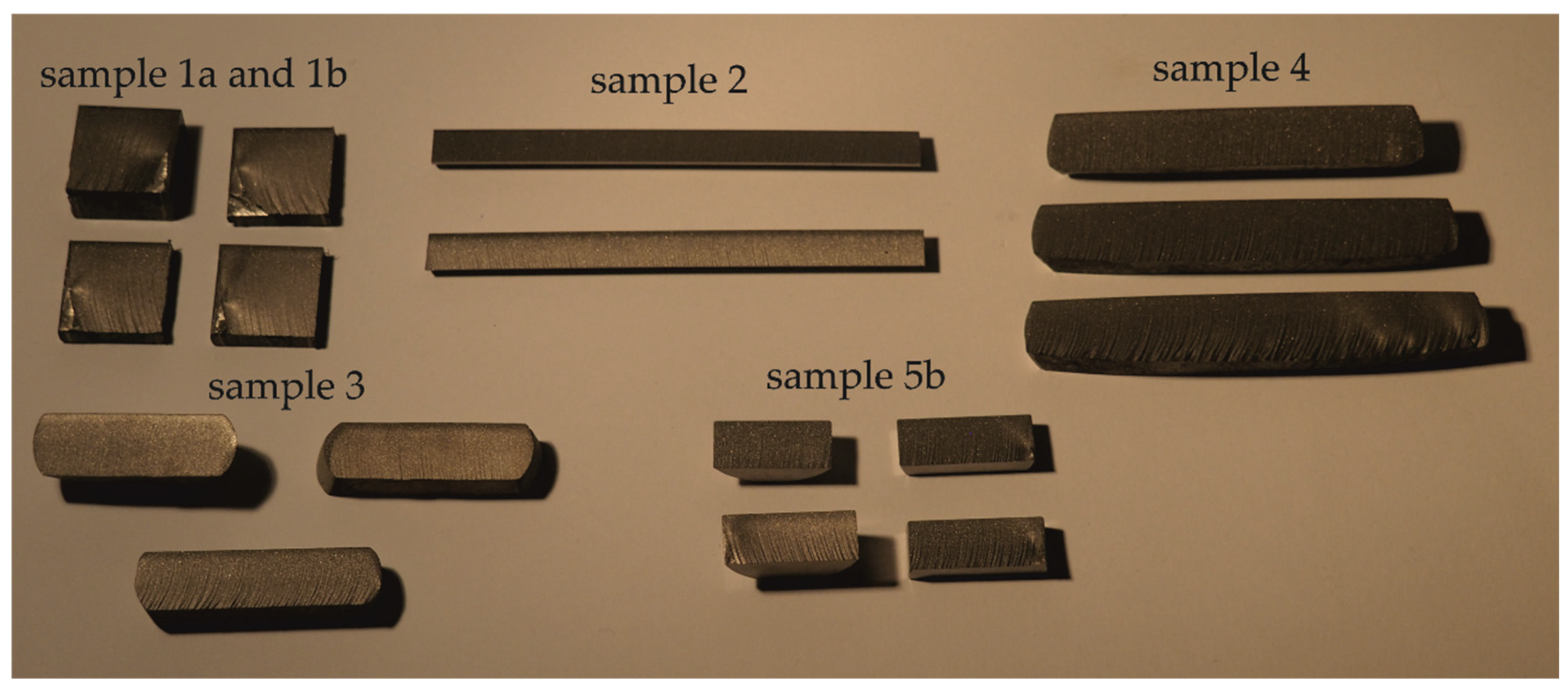
| Sample 1a | TiCP2 | room-temperature two pass ECAP |
| Sample 1b | TiCP2 | room-temperature two pass ECAP, 10 years of aging |
| Sample 2 | Ti6Al4V | hot forward extrusion (900 °C) |
| Sample 3 | Ti6Al4V | hot forging (900 °C, deformation ratio 60%), 4 years of aging |
| Sample 4 | Ti6Al4V | three-step cold stamping (deformation ratio 45%), 4 years of aging |
| Sample 5a | 50Ni-50Ti | as-cast by VIM |
| Sample 5b | 50Ni-50Ti | rotary swaged after VIM (swaging degree 0.9) |
| Sample 6 | TiCP2 | as-cast, aging unknown |
| Sample | Material Thickness (mm) | Traverse Speed Sets (mm/min) |
|---|---|---|
| Sample 1a | 20 | 30, 40, 60 |
| Sample 1b | 20 | 50, 75, 100, 125 |
| Sample 2 | 8 | 100, 150, 200 |
| Sample 3 | 12 | 100, 150, 200 |
| Sample 4 | 12.5–13.5 | 100, 150, 200 |
| Sample 5b | 10 | 100, 150, 200 |
| Sample 6 | 25 | 30, 60, 90 |
| Sample | Thickness (mm) | Traverse Speed (mm/min) | Average Declination Angle (°) |
|---|---|---|---|
| Sample 1a | 20 | 30 | 10.26 |
| 40 | 12.73 | ||
| 60 | 19.18 | ||
| Sample 1b | 20 | 50 | 12.46 |
| 75 | 17.36 | ||
| 100 | 21.80 | ||
| 125 | 26.31 | ||
| Sample 2 | 8 | 100 | 10.43 |
| 150 | 12.31 | ||
| 200 | 15.66 | ||
| Sample 3 | 12 | 100 | 12.25 |
| 150 | 17.30 | ||
| 200 | 27.00 | ||
| Sample 4 | 12.5 | 100 | 13.80 |
| 13.2 | 150 | 21.52 | |
| 13.5 | 200 | 32.60 | |
| Sample 5b | 10 | 100 | 11.36 |
| 150 | 15.36 | ||
| 200 | 21.66 | ||
| Sample 6 | 25 | 30 | 10.72 |
| 60 | 24.03 | ||
| 90 | 42.52 |
| MADA * (°) | RADA ** (°) | RADA ** with Aging (°) | Average RADA ** with Aging (°) | |
|---|---|---|---|---|
| Sample 1a | 10.26 | 12.09 | 12.09 | |
| 0 years | 12.73 | 11.26 | 11.26 | 11.55 |
| 19.18 | 11.30 | 11.30 | ||
| Sample 1b | 12.46 | 8.81 | 12.32 | |
| 10 years | 17.36 | 8.18 | 11.70 | 8.03 |
| 21.80 | 7.71 | 11.22 | ||
| 26.31 | 7.44 | 10.96 | ||
| Sample 2 | 10.43 | 14.58 | 14.58 | |
| 0 years | 12.31 | 11.46 | 11.46 | 12.33 |
| 15.66 | 10.94 | 10.94 | ||
| Sample 3 | 12.25 | 9.32 | 10.72 | |
| 4 years | 17.30 | 8.77 | 10.17 | 10.85 |
| 27.00 | 10.27 | 11.67 | ||
| Sample 4 | 13.80 | 9.87 | 11.27 | |
| 4 years | 21.52 | 9.46 | 10.86 | 11.31 |
| 32.60 | 10.39 | 11.79 | ||
| Sample 5b | 11.36 | 11.36 | 11.36 | |
| 0 years | 15.36 | 10.24 | 10.24 | 10.81 |
| 21.66 | 10.83 | 10.83 | ||
| Sample 6 | 10.72 | 9.04 | 10.09 | |
| 3 years | 24.03 | 10.13 | 11.18 | 11.42 |
| 42.52 | 11.95 | 13.00 | ||
| Sample 6 | 10.72 | 9.04 | 10.44 | |
| 4 years | 24.03 | 10.13 | 11.53 | 11.77 |
| 42.52 | 11.95 | 13.35 |
Publisher’s Note: MDPI stays neutral with regard to jurisdictional claims in published maps and institutional affiliations. |
© 2021 by the authors. Licensee MDPI, Basel, Switzerland. This article is an open access article distributed under the terms and conditions of the Creative Commons Attribution (CC BY) license (https://creativecommons.org/licenses/by/4.0/).
Share and Cite
Štefek, A.; Tyč, M. Impact of Preparation of Titanium Alloys on Their Abrasive Water Jet Machining. Materials 2021, 14, 7768. https://doi.org/10.3390/ma14247768
Štefek A, Tyč M. Impact of Preparation of Titanium Alloys on Their Abrasive Water Jet Machining. Materials. 2021; 14(24):7768. https://doi.org/10.3390/ma14247768
Chicago/Turabian StyleŠtefek, Adam, and Martin Tyč. 2021. "Impact of Preparation of Titanium Alloys on Their Abrasive Water Jet Machining" Materials 14, no. 24: 7768. https://doi.org/10.3390/ma14247768