
Dynamic Single-Fiber Pull-Out of Polypropylene Fibers Produced with Different Mechanical and Surface Properties for Concrete Reinforcement

 ,
, 
Abstract
:1. Introduction
2. Materials and Methods
2.1. Fiber Production and Surface Treatment
2.2. Concrete Matrix
2.3. Fiber Surface Characterization
2.4. Mechanical Testing of the Fibers
2.5. Differential Scanning Calorimetry
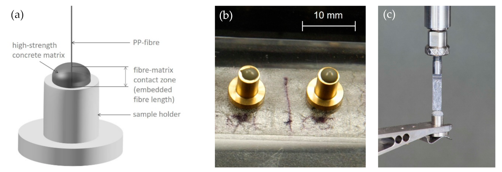
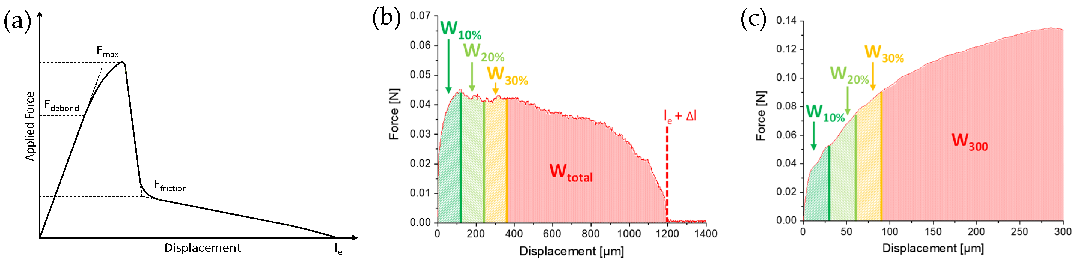
2.6. Single-Fiber Pull-Out Tests (SFPO)
3. Results and Discussion
3.1. Mechanical Properties of the Fibers
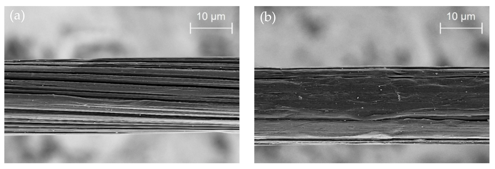
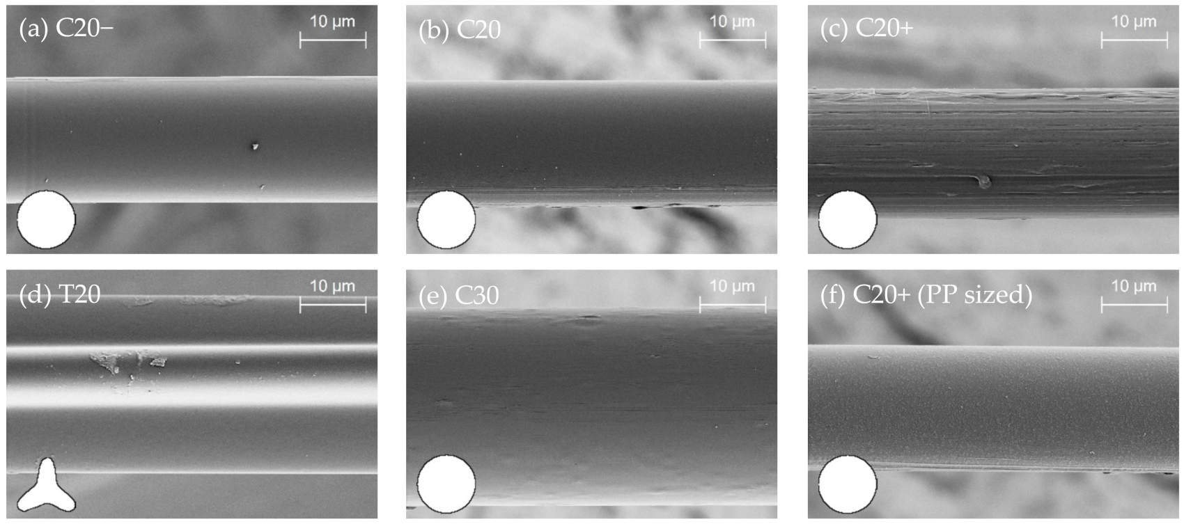
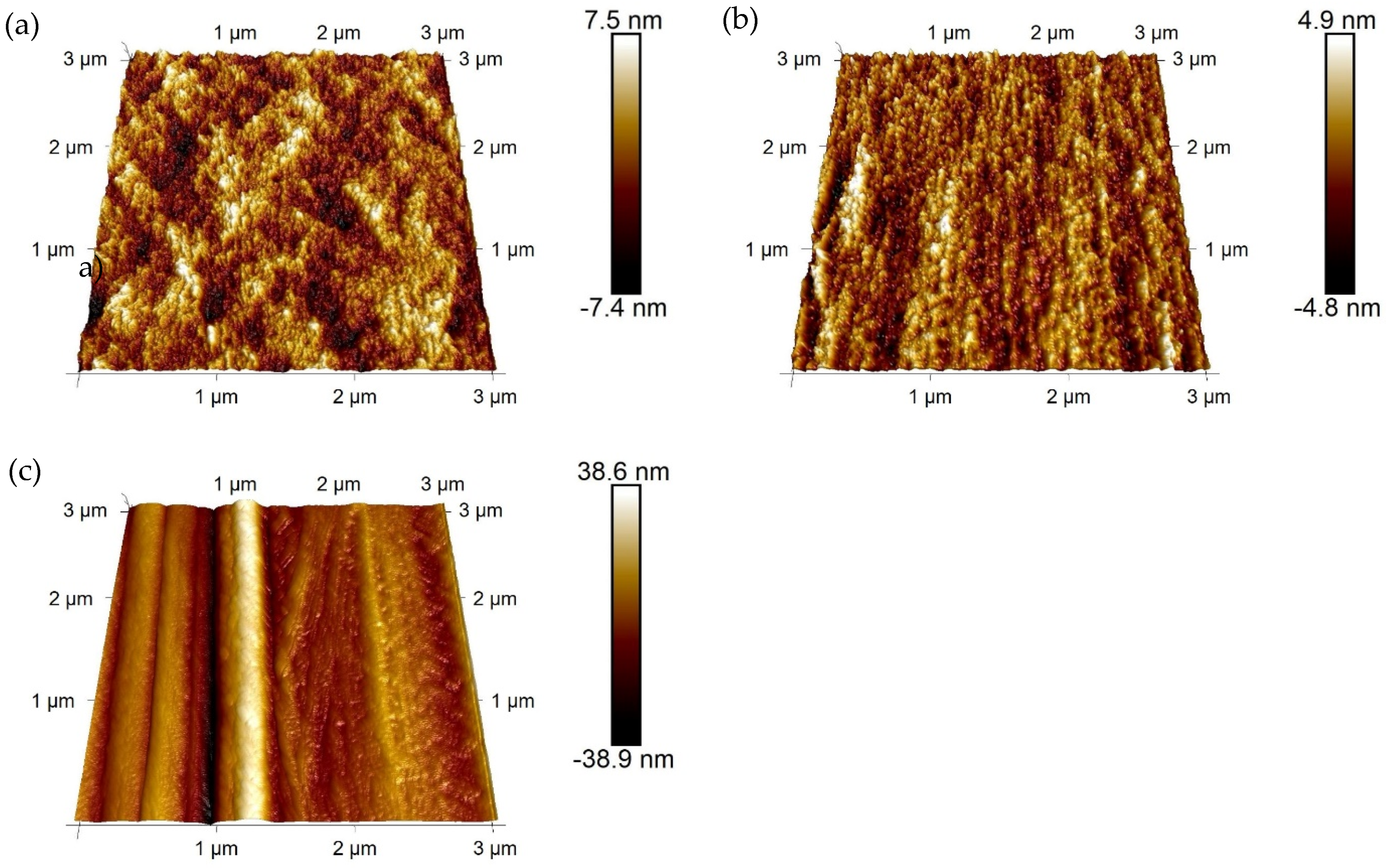
3.2. Surface Structure and Roughness
3.3. Contact Angle
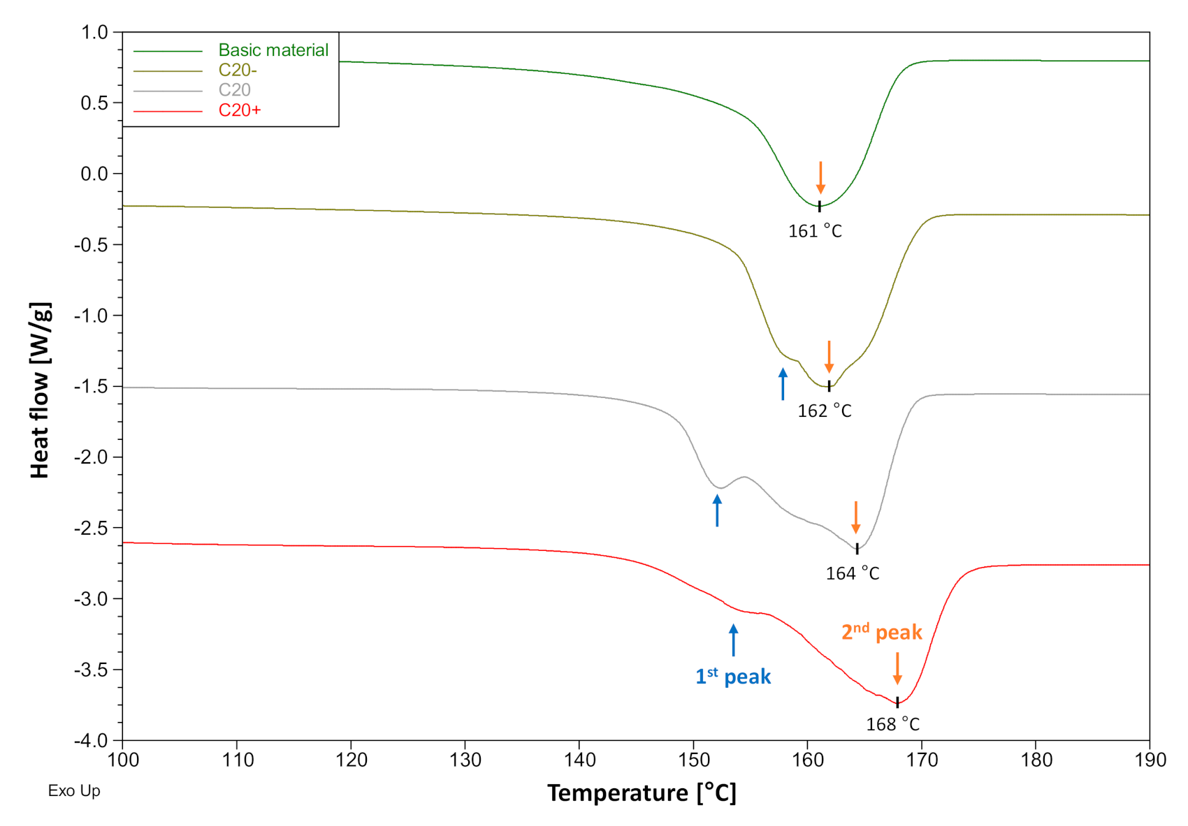
3.4. Crystallinity
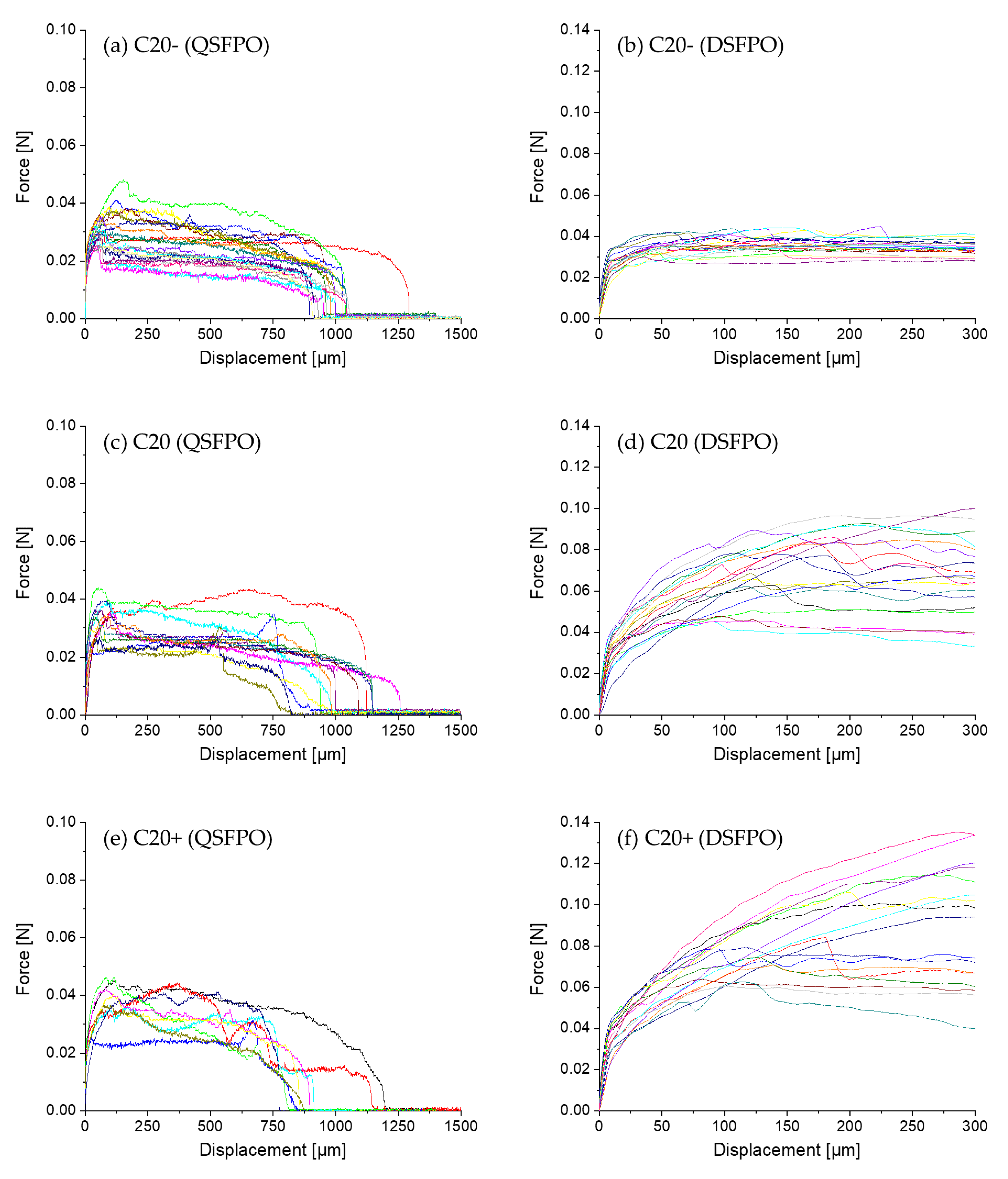
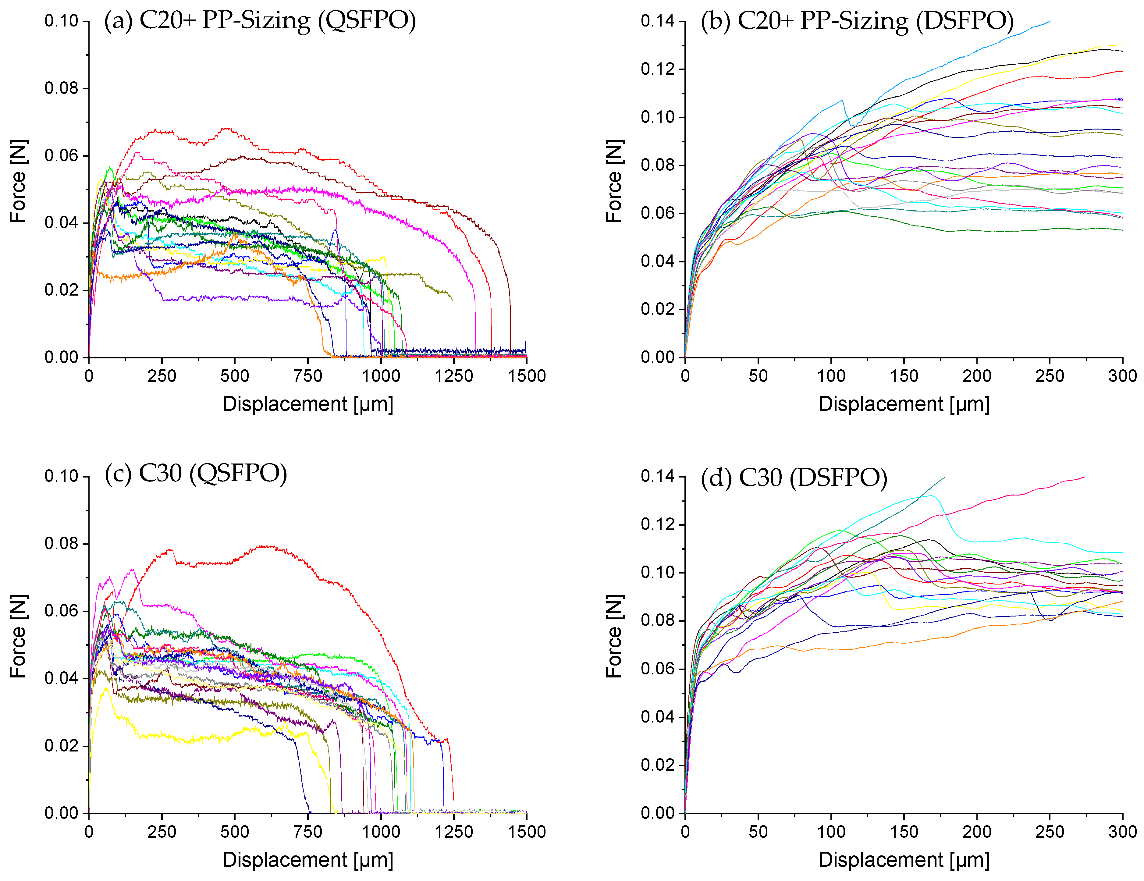
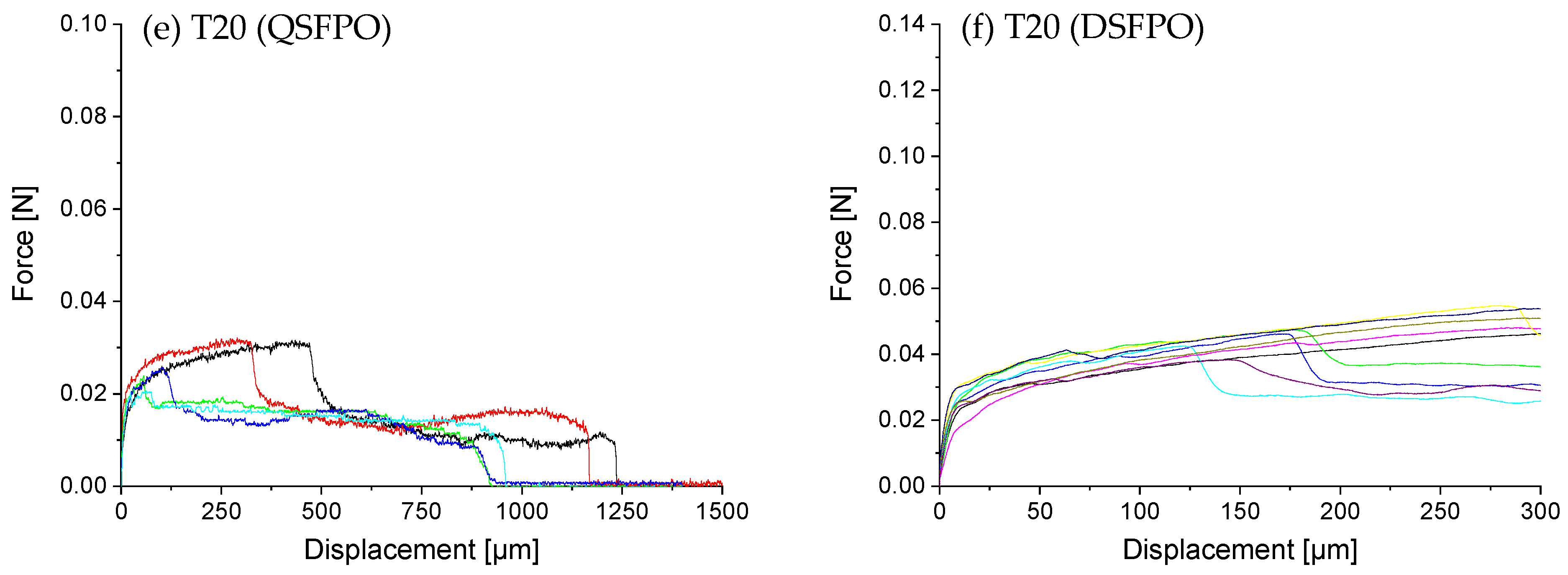
3.5. Quasi-Static and Dynamic Fiber Pull-Out
4. Conclusions
Author Contributions
Funding
Data Availability Statement
Acknowledgments
Conflicts of Interest
References
- Kakooei, S.; Akil, H.M.; Jamshidi, M.; Rouhi, J. The Effects of Polypropylene Fibers on the Properties of Reinforced Concrete Structures. Constr. Build. Mater. 2012, 27, 73–77. [Google Scholar] [CrossRef]
- Combrinck, R.; Boshoff, W.P. Typical Plastic Shrinkage Cracking Behaviour of Concrete. Mag. Concr. Res. 2013, 65, 486–493. [Google Scholar] [CrossRef]
- Banthia, N.; Gupta, R. Influence of Polypropylene Fiber Geometry on Plastic Shrinkage Cracking in Concrete. Cem. Concr. Res. 2006, 36, 1263–1267. [Google Scholar] [CrossRef]
- Song, P.S.; Hwang, S.; Sheu, B.C. Strength Properties of Nylon- and Polypropylene-Fiber-Reinforced Concretes. Cem. Concr. Res. 2005, 35, 1546–1550. [Google Scholar] [CrossRef]
- Zhang, L.; Wang, X.X.; Zheng, G. Effect of Polypropylene Fibers on the Strength and Elastic Modulus of Soil-Cement. In Proceedings of the Geosynthetics in Civil and Environmental Engineering; Li, G., Chen, Y., Tang, X., Eds.; Springer: Berlin/Heidelberg, Germany, 2009; pp. 386–391. [Google Scholar]
- Li, Y.; Pimienta, P.; Pinoteau, N.; Tan, K.H. Effect of Aggregate Size and Inclusion of Polypropylene and Steel Fibers on Explosive Spalling and Pore Pressure in Ultra-High-Performance Concrete (UHPC) at Elevated Temperature. Cem. Concr. Compos. 2019, 99, 62–71. [Google Scholar] [CrossRef]
- Noumowe, A. Mechanical Properties and Microstructure of High Strength Concrete Containing Polypropylene Fibres Exposed to Temperatures up to 200 °C. Cem. Concr. Res. 2005, 35, 2192–2198. [Google Scholar] [CrossRef]
- Xiao, J.; Falkner, H. On Residual Strength of High-Performance Concrete with and without Polypropylene Fibres at Elevated Temperatures. Fire Saf. J. 2006, 41, 115–121. [Google Scholar] [CrossRef]
- Pistol, K.; Weise, F.; Meng, B.; Diederichs, U. Polypropylene Fibres and Micro Cracking in Fire Exposed Concrete. AMR 2014, 897, 284–289. [Google Scholar] [CrossRef]
- Mindess, S.; Vondran, G. Properties of Concrete Reinforced with Fibrillated Polypropylene Fibres under Impact Loading. Cem. Concr. Res. 1988, 18, 109–115. [Google Scholar] [CrossRef]
- Pakravan, H.; Jamshidi, M.; Latifi, M. The Effect of Hybridization and Geometry of Polypropylene Fibers on Engineered Cementitious Composites Reinforced by Polyvinyl Alcohol Fibers. J. Compos. Mater. 2016, 50, 1007–1020. [Google Scholar] [CrossRef]
- Alavi Nia, A.; Hedayatian, M.; Nili, M.; Sabet, V.A. An Experimental and Numerical Study on How Steel and Polypropylene Fibers Affect the Impact Resistance in Fiber-Reinforced Concrete. Int. J. Impact Eng. 2012, 46, 62–73. [Google Scholar] [CrossRef]
- Li, V.C. On Engineered Cementitious Composites (ECC). J. Adv. Concr. Technol. 2003, 1, 215–230. [Google Scholar] [CrossRef] [Green Version]
- Curosu, I.; Liebscher, M.; Mechtcherine, V.; Bellmann, C.; Michel, S. Tensile Behavior of High-Strength Strain-Hardening Cement-Based Composites (HS-SHCC) Made with High-Performance Polyethylene, Aramid and PBO Fibers. Cem. Concr. Res. 2017, 98, 71–81. [Google Scholar] [CrossRef]
- Yu, J.; Yao, J.; Lin, X.; Li, H.; Lam, J.Y.K.; Leung, C.K.Y.; Sham, I.M.L.; Shih, K. Tensile Performance of Sustainable Strain-Hardening Cementitious Composites with Hybrid PVA and Recycled PET Fibers. Cem. Concr. Res. 2018, 107, 110–123. [Google Scholar] [CrossRef]
- Construction Materials: Their Nature and Behaviour, Fourth Edition. Available online: https://www.crcpress.com/Construction-Materials-Their-Nature-and-Behaviour-Fourth-Edition/Domone-Illston/p/book/9781315272436 (accessed on 21 May 2019).
- Juijn, J.A. Fibers. In Handbook of Polymer Reaction Engineering; John Wiley & Sons, Ltd: Hoboken, NJ, USA, 2005; pp. 911–970. ISBN 978-3-527-61987-0. [Google Scholar]
- Li, V.C. Engineered Cementitious Composites (ECC)–Material, Structural, and Durability Performance. In Concrete Construction Engineering Handbook; Nawy, E.G., Ed.; CRC Press: Boca Raton, FL, USA, 2008; Chapter 24; pp. 1–40. ISBN 978-0-8493-7492-0. [Google Scholar]
- de LHONEUX, B.; Kalbskopf, R.; Kim, P.; Li, V.C.; Lin, Z.; Vidts, D.; Wang, S.; Wu, H.-C. Development of High Tenacity Polypropylene Fibers for Cementitious Composites. In Proceedings of the JCI International Workshop on Ductile Fiber Reinforced Cementitious Composites (DFRCC)-Application and Evaluation (DFRCC-2002), Takayama, Japan, 21–22 October 2002; pp. 121–131. [Google Scholar]
- Lin, X.; Yu, J.; Li, H.; Lam, J.Y.K.; Shih, K.; Sham, I.M.L.; Leung, C.K.Y. Recycling Polyethylene Terephthalate Wastes as Short Fibers in Strain-Hardening Cementitious Composites (SHCC). J. Hazard. Mater. 2018, 357, 40–52. [Google Scholar] [CrossRef] [PubMed]
- Trejbal, J.; Kopecký, L.; Tesárek, P.; Fládr, J.; Antoš, J.; Somr, M.; Nežerka, V. Impact of Surface Plasma Treatment on the Performance of PET Fiber Reinforcement in Cementitious Composites. Cem. Concr. Res. 2016, 89, 276–287. [Google Scholar] [CrossRef]
- Zych, T.; Krasodomski, W. Polyolefin fibres used in cementitious composites–manufacturing, properties and application. Czas. Tech. 2016, 2016, 155–177. [Google Scholar] [CrossRef]
- Won, J.-P.; Lim, D.-H.; Park, C.-G. Bond Behaviour and Flexural Performance of Structural Synthetic Fibre-Reinforced Concrete. Mag. Concr. Res. 2006, 58, 401–410. [Google Scholar] [CrossRef]
- Singh, S.; Shukla, A.; Brown, R. Pullout Behavior of Polypropylene Fibers from Cementitious Matrix. Cem. Concr. Res. 2004, 34, 1919–1925. [Google Scholar] [CrossRef]
- Leaders in Concrete & Concrete Products: BarChipInc. Barchip. Available online: https://barchip.com/product/ (accessed on 31 March 2020).
- Li, V.C.; Wu, H.-C.; Chan, Y.-W. Effect of Plasma Treatment of Polyethylene Fibers on Interface and Ementitious Composite Properties. J. Am. Ceram. Soc. 1996, 79, 700–704. [Google Scholar] [CrossRef] [Green Version]
- Liu, T.; Wei, H.; Zhou, A.; Zou, D.; Jian, H. Multiscale Investigation on Tensile Properties of Ultra-High Performance Concrete with Silane Coupling Agent Modified Steel Fibers. Cem. Concr. Compos. 2020, 111, 103638. [Google Scholar] [CrossRef]
- Zhou, A.; Yu, Z.; Wei, H.; Tam, L.; Liu, T.; Zou, D. Understanding the Toughening Mechanism of Silane Coupling Agents in the Interfacial Bonding in Steel Fiber-Reinforced Cementitious Composites. ACS Appl. Mater. Interfaces 2020, 12, 44163–44171. [Google Scholar] [CrossRef]
- Wang, Y.; Li, V.C.; Backer, S. Modelling of Fibre Pull-out from a Cement Matrix. Int. J. Cem. Compos. Lightweight Concr. 1988, 10, 143–149. [Google Scholar] [CrossRef]
- Banthia, N. A Study of Some Factors Affecting the Fiber–Matrix Bond in Steel Fiber Reinforced Concrete. Can. J. Civ. Eng. 1990, 17, 610–620. [Google Scholar] [CrossRef]
- Stang, H.; Shah, S.P. Failure of Fibre-Reinforced Composites by Pull-out Fracture. J. Mater. Sci. 1986, 21, 953–957. [Google Scholar] [CrossRef]
- Wu, Z.; Khayat, K.H.; Shi, C. How Do Fiber Shape and Matrix Composition Affect Fiber Pullout Behavior and Flexural Properties of UHPC? Cem. Concr. Compos. 2018, 90, 193–201. [Google Scholar] [CrossRef] [Green Version]
- Robins, P.; Austin, S.; Jones, P. Pull-out Behaviour of Hooked Steel Fibres. Mater. Struct. 2002, 35, 9. [Google Scholar] [CrossRef]
- Wille, K.; Naaman, A.E. Bond Stress-Slip Behavior of Steel Fibers Embedded in Ultra High Performance Concrete. In Proceedings of the 18th European conference on fracture (ECF 18), Dresden, Germany, 30 August–3 September 2010; pp. 99–111. [Google Scholar]
- Xu, M.; Hallinan, B.; Wille, K. Effect of Loading Rates on Pullout Behavior of High Strength Steel Fibers Embedded in Ultra-High Performance Concrete. Cem. Concr. Compos. 2016, 70, 98–109. [Google Scholar] [CrossRef]
- Tai, Y.-S.; El-Tawil, S. High Loading-Rate Pullout Behavior of Inclined Deformed Steel Fibers Embedded in Ultra-High Performance Concrete. Constr. Build. Mater. 2017, 148, 204–218. [Google Scholar] [CrossRef]
- Kühnert, I.; Spörer, Y.; Brünig, H.; Tran, N.H.A.; Rudolph, N. Processing of Poly(lactic Acid). In Industrial Applications of Poly(lactic acid); Di Lorenzo, M.L., Androsch, R., Eds.; Springer: Cham, Switzerland, 2018; pp. 1–33. ISBN 978-3-319-75459-8. [Google Scholar]
- Curosu, I.; Mechtcherine, V.; Millon, O. Effect of Fiber Properties and Matrix Composition on the Tensile Behavior of Strain-Hardening Cement-Based Composites (SHCCs) Subject to Impact Loading. Cem. Concr. Res. 2016, 82, 23–35. [Google Scholar] [CrossRef]
- Mäder, E. Study of Fibre Surface Treatments for Control of Interphase Properties in Composites. Compos. Sci. Technol. 1997, 57, 1077–1088. [Google Scholar] [CrossRef]
- Standard Test Methods for Linear Density of Textile Fibers; ASTM D1577-07(2018); ASTM International: West Conshohocken, PA, USA, 2018; Available online: www.astm.org (accessed on 1 February 2021).
- Ehrenstein, G.W.; Riedel, G.; Trawiel, P. Praxis der thermischen Analyse von Kunststoffen; Carl Hanser Verlag GmbH & Co. KG: München, Germany, 2003; ISBN 978-3-446-22340-0. [Google Scholar]
- Mäder, E.; Grundke, K.; Jacobasch, H.-J.; Wachinger, G. Surface, Interphase and Composite Property Relations in Fibre-Reinforced Polymers. Composites 1994, 25, 739–744. [Google Scholar] [CrossRef]
- Scheffler, C.; Zhandarov, S.; Mäder, E. Alkali Resistant Glass Fiber Reinforced Concrete: Pull-out Investigation of Interphase Behavior under Quasi-Static and High Rate Loading. Cem. Concr. Res. 2017, 84, 19–27. [Google Scholar] [CrossRef]
- Zhandarov, S.; Mäder, E.; Scheffler, C.; Kalinka, G.; Poitzsch, C.; Fliescher, S. Investigation of Interfacial Strength Parameters in Polymer Matrix Composites: Compatibility and Reproducibility. Adv. Ind. Eng. Polym. Res. 2018, 1, 82–92. [Google Scholar] [CrossRef]
- Beyreuther, R.; Brünig, H. Dynamics of Fibre Formation and Processing: Modelling and Application in Fibre and Textile Industry; Springer: Berlin/Heidelberg, Germany, 2007; ISBN 978-3-540-46221-7. [Google Scholar]
- Opdahl, A.; Somorjai, G.A. Stretched Polymer Surfaces: Atomic Force Microscopy Measurement of the Surface Deformation and Surface Elastic Properties of Stretched Polyethylene. J. Polym. Sci. Part B Polym. Phys. 2001, 39, 2263–2274. [Google Scholar] [CrossRef]
- Huang, F.; Wei, Q.; Wang, X.; Xu, W. Dynamic Contact Angles and Morphology of PP Fibres Treated with Plasma. Polym. Test. 2006, 25, 22–27. [Google Scholar] [CrossRef]
- Nygård, P.; Grundke, K.; Mäder, E.; Bellmann, C. Wetting Kinetics and Adhesion Strength between Polypropylene Melt and Glass Fibre: Influence of Chemical Reactivity and Fibre Roughness. J. Adhes. Sci. Technol. 2002, 16, 1781–1808. [Google Scholar] [CrossRef]
- Yu, Y.; White, J.L. Comparison of Structure Development in Quiescent Crystallization, Die Extrusion and Melt Spinning of Isotactic Polypropylene and Its Compounds Containing Fillers and Nucleating Agents. Polym. Eng. Sci. 2001, 41, 1292–1298. [Google Scholar] [CrossRef]
- Vogel, R.; Gedan-Smolka, M.; Häussler, L.; Brünig, H. Evaluation of the Crystallization of Polypropylene at Melt Spinning Conditions Using the Green Chemical Orotic Acid as Nucleating Agent. Adv. Res. Text Eng. 2018, 3. [Google Scholar] [CrossRef]
- Zhandarov, S.; Mäder, E. Characterization of Fiber/Matrix Interface Strength: Applicability of Different Tests, Approaches and Parameters. Compos. Sci. Technol. 2005, 65, 149–160. [Google Scholar] [CrossRef]
- Scheer, R.J.; Nairn, J.A. A Comparison of Several Fracture Mechanics Methods for Measuring Interfacial Toughness with Microbond Tests. J. Adhes. 1995, 53, 45–68. [Google Scholar] [CrossRef]
- Mäder, E.; Scheffler, C.; Miene, A.; Bremen eV, F.; Fliescher, S.; Mörschel, U.; Poitzsch, C. FIMATEST–A New Testing System to Determine the Fibre-Matrix Adhesion Strength by Menas of Pull-out Tests. In Proceedings of the 56th Dornbirn-MFC, Dornbirn, Austria, 13–15 September 2017; Volume 56. [Google Scholar]
- Ranjbarian, M.; Mechtcherine, V.; Zhang, Z.; Curosu, I.; Storm, J.; Kaliske, M. Locking Front Model for Pull-out Behaviour of PVA Microfibre Embedded in Cementitious Matrix. Cem. Concr. Res. 2019, 103, 318–330. [Google Scholar] [CrossRef]
- Curosu, I.; Liebscher, M.; Alsous, G.; Muja, E.; Li, H.; Drechsler, A.; Frenzel, R.; Synytska, A.; Mechtcherine, V. Tailoring the Crack-Bridging Behavior of Strain-Hardening Cement-Based Composites (SHCC) by Chemical Surface Modification of Poly(Vinyl Alcohol) (PVA) Fibers. Cem. Concr. Res. 2020, 114, 103722. [Google Scholar] [CrossRef]
- Bindiganavile, V.; Banthia, N. Impact Response of the Fiber-Matrix Bond in Concrete. Can. J. Civ. Eng. 2005, 32, 924–933. [Google Scholar] [CrossRef]


| Fiber Type | Target Diameter (µm) | Cross-Section Shape | Surface Treatment | Draw Ratio |
|---|---|---|---|---|
| C10 | 10 | circular | none | 1.6 |
| C20 | 20 | circular | none | 1.7 |
| C30 | 30 | circular | none | 1.9 |
| C20+ | 20 | circular | none | 2.25 |
| C20− | 20 | circular | none | 1.0 |
| T20 | 20 | trilobal | none | 1.0 |
| C20+ (PP-sized) | 20 | circular | PP sizing | 2.25 |
| Components | (kg/m3) |
|---|---|
| CEM I 52.5 R-SR3/NA (Holcim, Switzerland) | 1460 |
| Silica fume Elkem 971-U (Elkem, Norway) | 292 |
| Quartz sand 0.06–0.2 mm (Strobel Quarzsand, Germany) | 145 |
| Superplasticizer Glenium ACE 460 (BASF, Germany) | 35 |
| Water | 315 |
| Fiber Type | Effective Diameter (µm) | Young’s Modulus (MPa) | Tensile Strength (MPa) | Strain at Break (%) |
|---|---|---|---|---|
| C10 | 12.9 ± 0.6 | 2.3 ± 0.3 | 269.9 ± 20.0 | 147.3 ± 23.6 |
| C20 | 19.4 ± 0.7 | 3.4 ± 0.1 | 348.5 ± 11.2 | 125.8 ± 9.5 |
| C30 | 29.5 ± 0.7 | 3.2 ± 0.2 | 375.5 ± 16.8 | 119.3 ± 12.1 |
| C20+ | 19.4 ± 1.0 | 4.6 ± 0.2 | 427.1 ± 14.3 | 76.3 ± 11.7 |
| C20− | 21.5 ± 1.2 | 2.6 ± 0.2 | 194.8 ± 9.0 | 228.8 ± 30.3 |
| T20 | (20.7 ± 1.6) * | 2.6 ± 0.1 | 183.5 ± 14.7 | 215.8 ± 20.5 |
| C20+ (PP-sized) | see C20+ | see C20+ | see C20+ | see C20+ |
| Fiber Type | Ra (nm) | Rmax (nm) |
|---|---|---|
| C20− | 2.79 ± 1.56 | 28.20 ± 20.71 |
| C20 | 2.38 ± 2.04 | 27.08 ± 18.63 |
| C20+ | 5.72 ± 1.82 | 56.92 ± 8.23 |
| Fiber Type | Contact Angle (°) |
|---|---|
| C10 | 90.5 ± 5.6 |
| C20 | 95.8 ± 5.2 |
| C30 | 102.3 ± 2.0 |
| C20+ | 90.0 ± 2.2 |
| C20− | 104.5 ± 7.6 |
| T20 | 93.4 ± 4.0 |
| C20+ (PP-sized) | 87.9 ± 5.2 |
| Fiber Type | Melting Temperature (°C) | Melting Enthalpy (J/g) | Crystallinity (%) |
|---|---|---|---|
| Basic PP material | 161 | 89.4 | 43.2 |
| C20− | 162 | 91.5 | 44.2 |
| C20 | 164 | 94.9 | 45.8 |
| C20+ | 168 | 87.3 | 42.2 |
| Quasi-Static | Dynamic | ||
|---|---|---|---|
| Fiber Type | W300 (Nm)·10−6 | Wtotal (Nm)·10−6 | W300 (Nm)·10−6 |
| C20− | 8.18 ± 1.82 | 23.42 ± 6.29 | 10.20 ± 0.95 |
| C20 | 8.53 ± 1.45 | 25.88 ± 7.00 | 18.31 ± 4.08 |
| C20+ | 10.12 ± 1.53 | 26.78 ± 6.70 | 22.34 ± 4.64 |
| T20 | 6.38 ± 1.47 | 17.20 ± 4.24 | 11.43 ± 1.51 |
| C20+ (PP-sized) | 12.03 ± 2.52 | 38.85 ± 16.42 | 23.46 ± 4.01 |
| C30 | 13.91 ± 2.66 | 41.68 ± 12.40 | 28.24 ± 3.83 |
Publisher’s Note: MDPI stays neutral with regard to jurisdictional claims in published maps and institutional affiliations. |
© 2021 by the authors. Licensee MDPI, Basel, Switzerland. This article is an open access article distributed under the terms and conditions of the Creative Commons Attribution (CC BY) license (http://creativecommons.org/licenses/by/4.0/).
Share and Cite
Wölfel, E.; Brünig, H.; Curosu, I.; Mechtcherine, V.; Scheffler, C. Dynamic Single-Fiber Pull-Out of Polypropylene Fibers Produced with Different Mechanical and Surface Properties for Concrete Reinforcement. Materials 2021, 14, 722. https://doi.org/10.3390/ma14040722
Wölfel E, Brünig H, Curosu I, Mechtcherine V, Scheffler C. Dynamic Single-Fiber Pull-Out of Polypropylene Fibers Produced with Different Mechanical and Surface Properties for Concrete Reinforcement. Materials. 2021; 14(4):722. https://doi.org/10.3390/ma14040722
Chicago/Turabian StyleWölfel, Enrico, Harald Brünig, Iurie Curosu, Viktor Mechtcherine, and Christina Scheffler. 2021. "Dynamic Single-Fiber Pull-Out of Polypropylene Fibers Produced with Different Mechanical and Surface Properties for Concrete Reinforcement" Materials 14, no. 4: 722. https://doi.org/10.3390/ma14040722
APA StyleWölfel, E., Brünig, H., Curosu, I., Mechtcherine, V., & Scheffler, C. (2021). Dynamic Single-Fiber Pull-Out of Polypropylene Fibers Produced with Different Mechanical and Surface Properties for Concrete Reinforcement. Materials, 14(4), 722. https://doi.org/10.3390/ma14040722