
Research on the Thermal Properties of Fireplace Concrete Materials Containing Various Mineral Aggregates Enriched by Organic and Inorganic Fibers

 , , ,
, , ,
Abstract
:1. Introduction
2. Research Significance
3. Materials and Methods
3.1. Materials and Mix Proportions
3.2. Research Methodology
3.2.1. Thermal Properties
3.2.2. Differential Thermal Analysis
3.2.3. Mechanical Pproperties
3.2.4. Microstructure of the Fireplace Concrete
4. Results
4.1. Thermal Properties
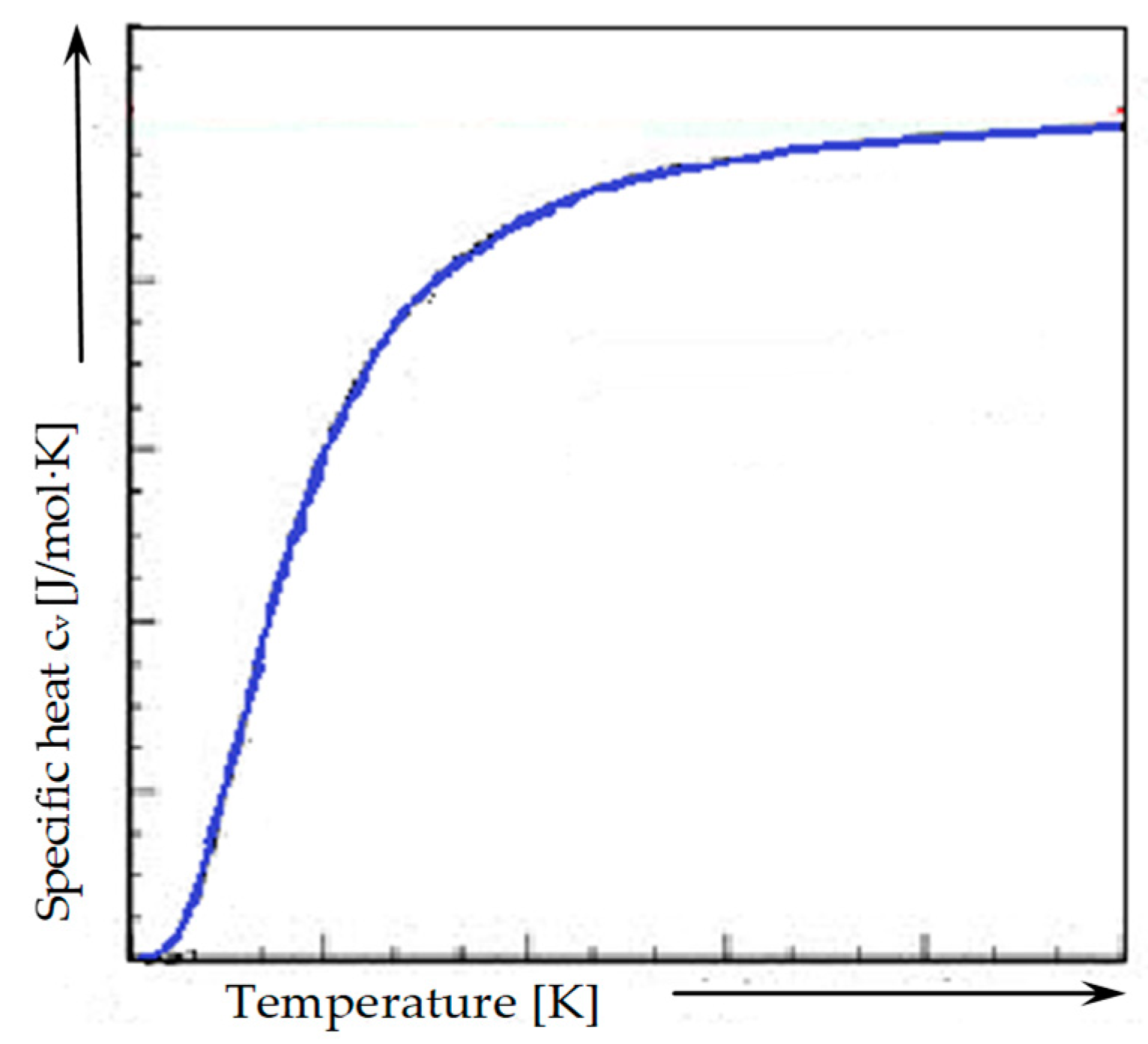
Calculation of Heat Capacity
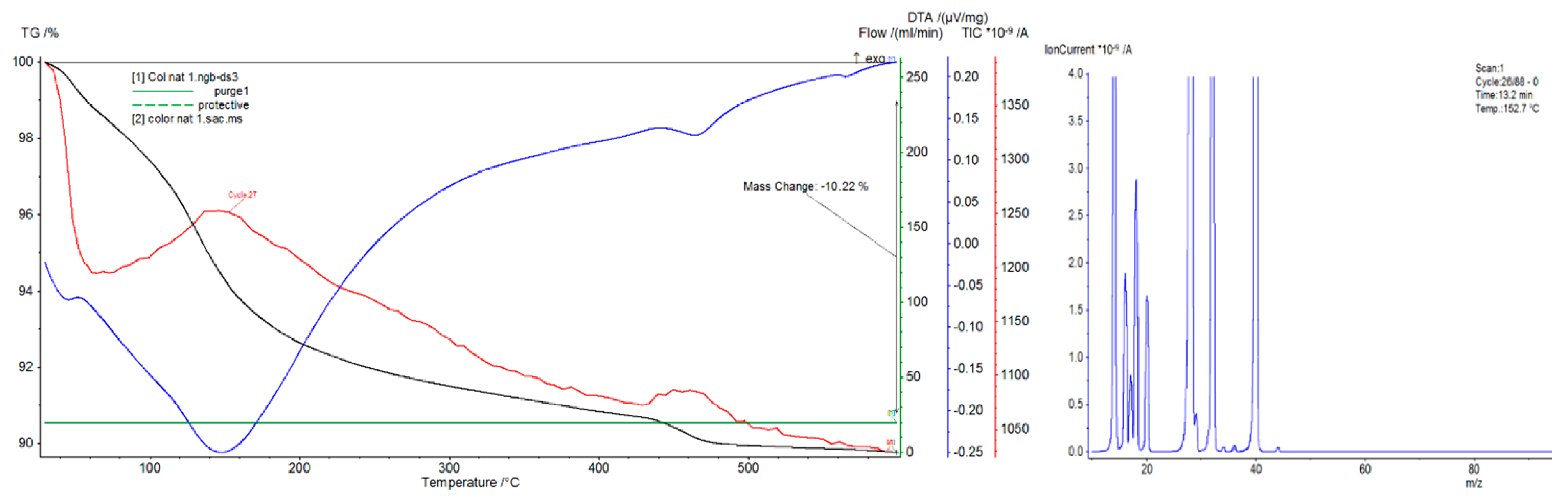
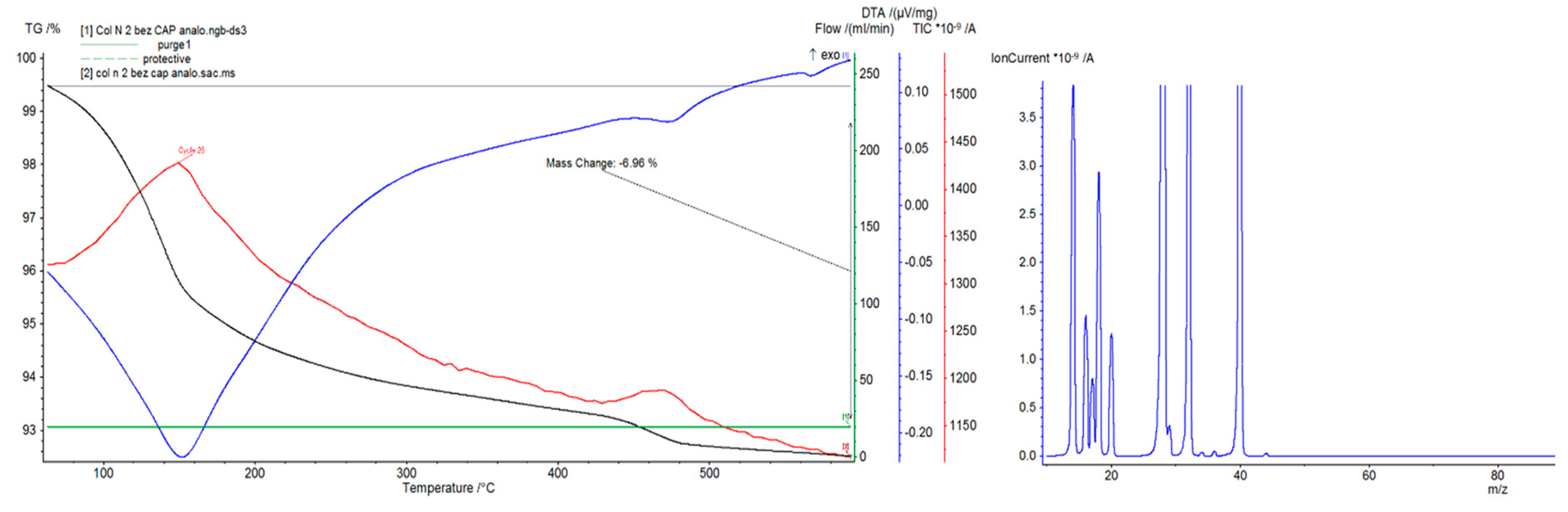
4.2. Differential Thermal Analysis
4.3. Mechanical Properties
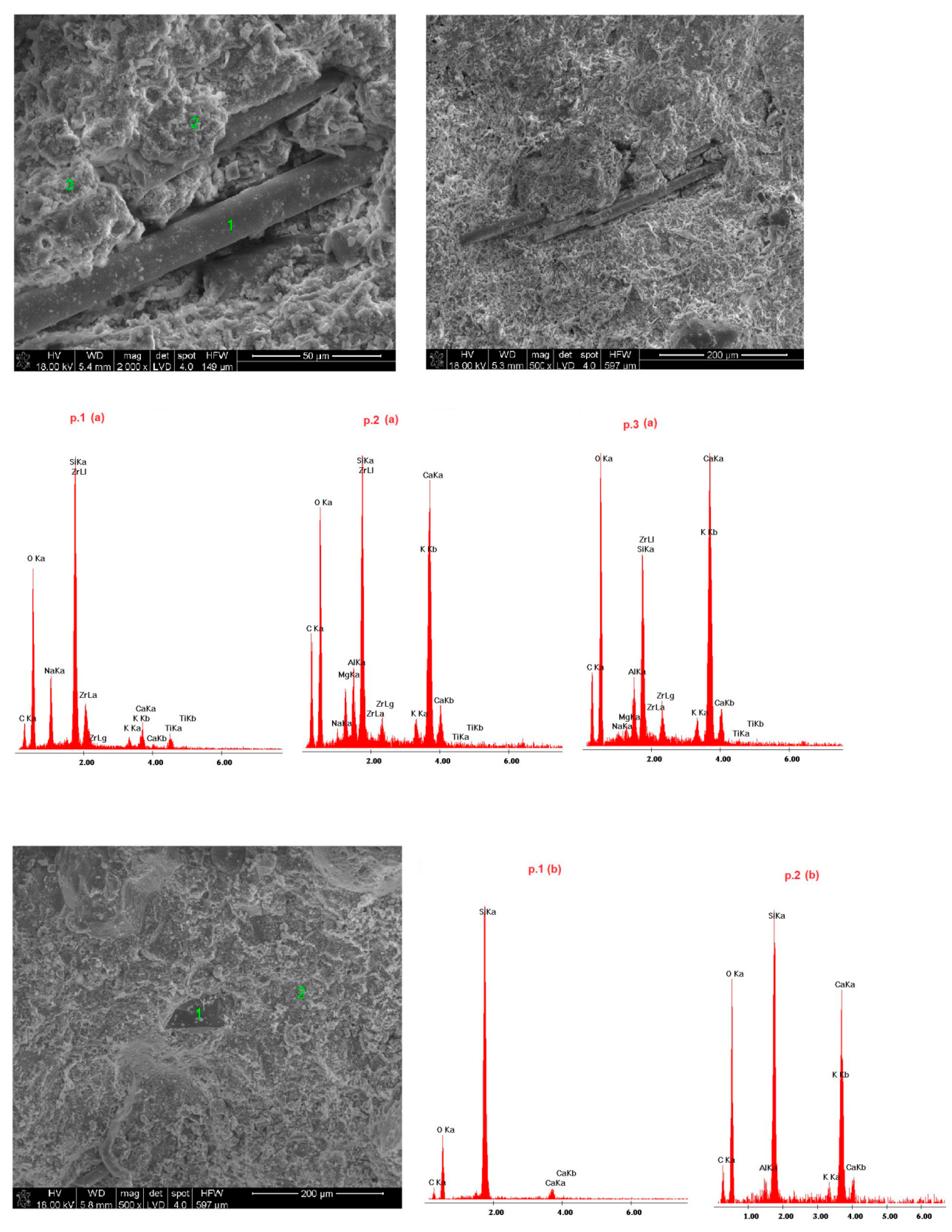
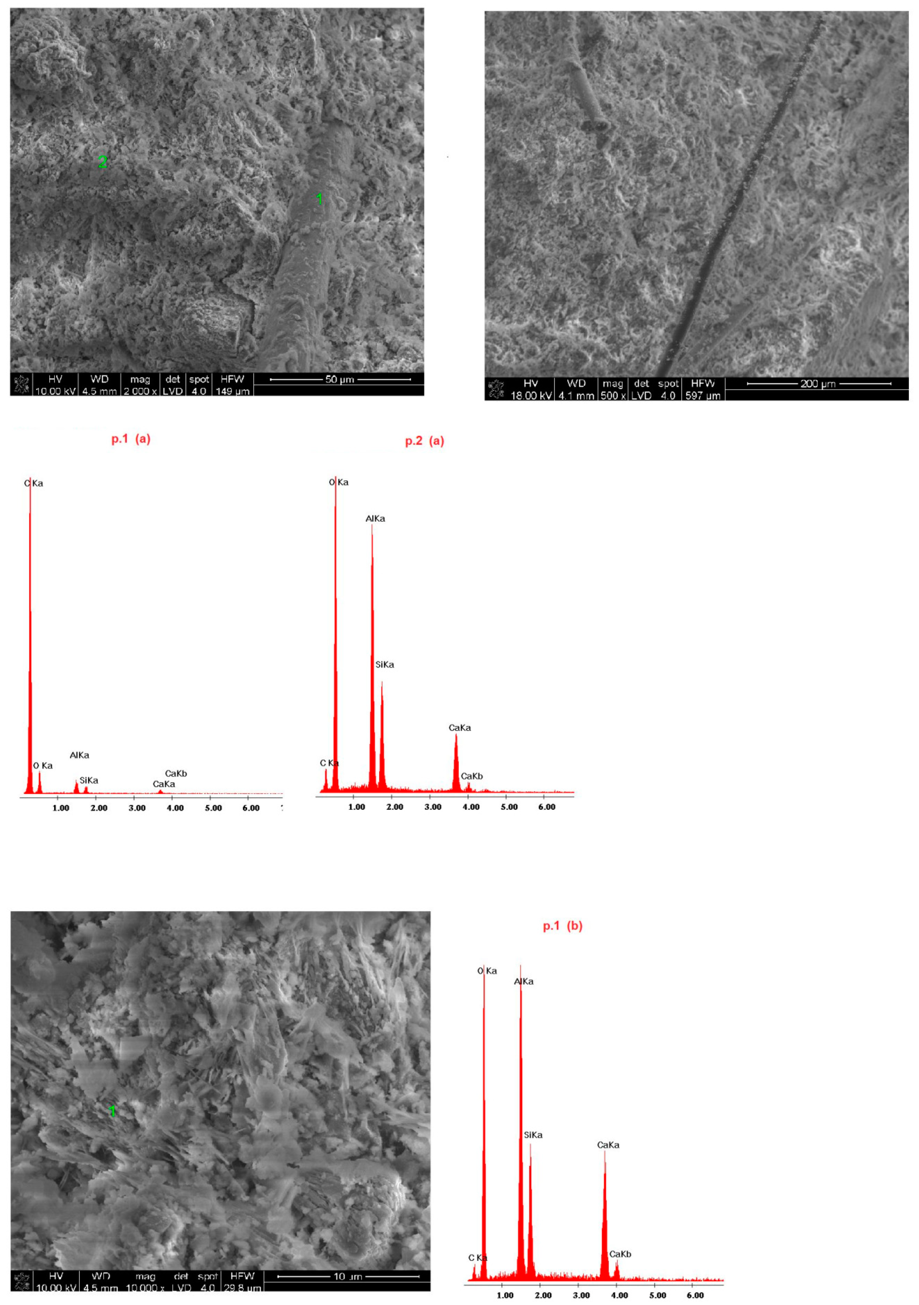
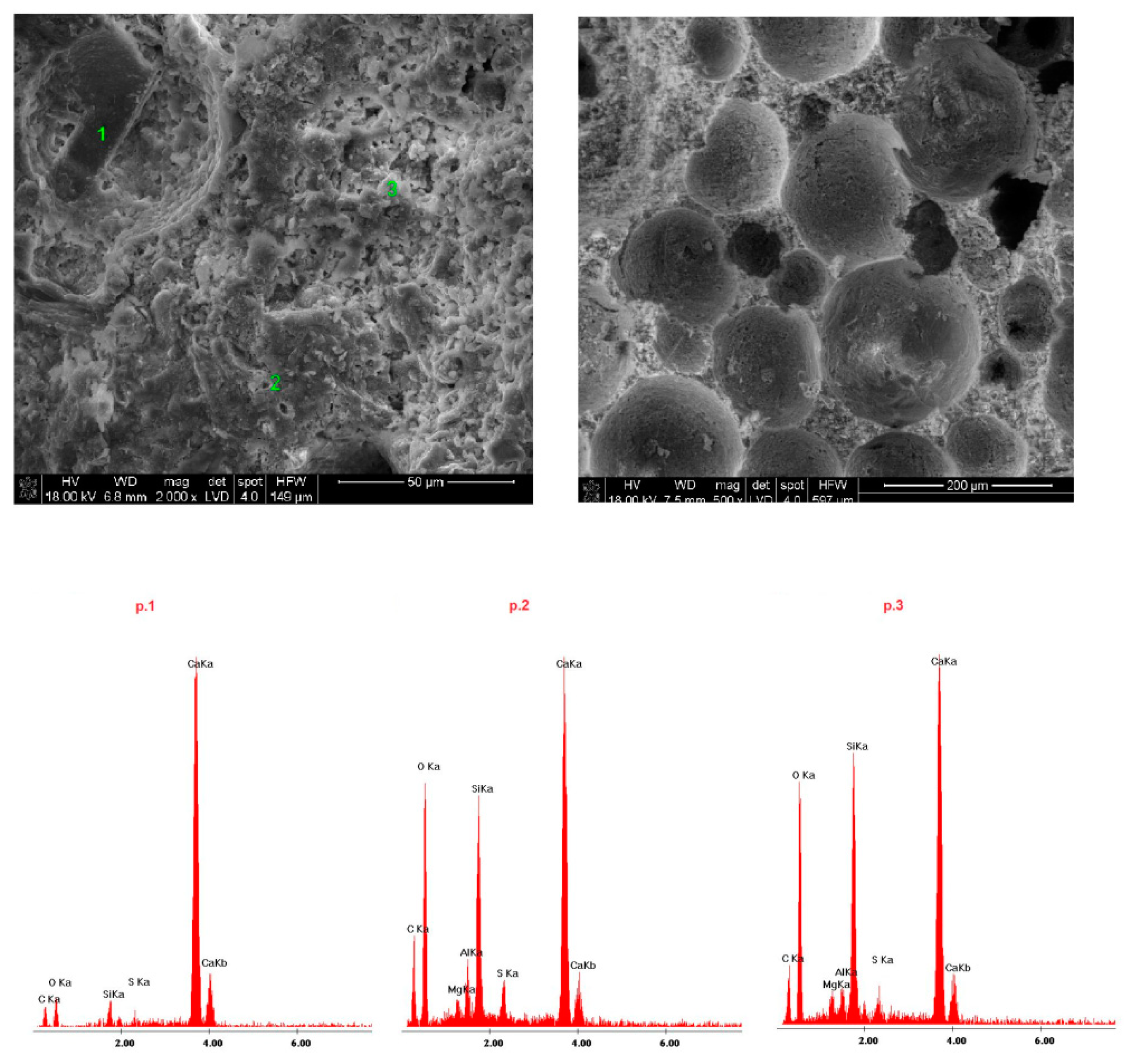
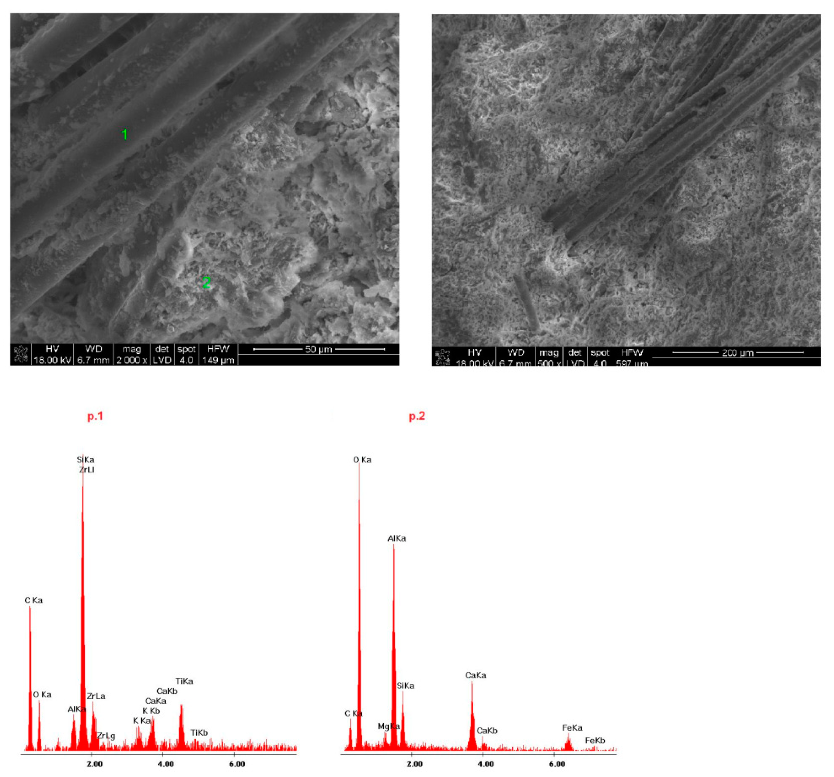
4.4. Microstructure of Fireplace Concrete
bellite: 2CaO·SiO2 + 2H2O → C1.5SH1.5 + 0.5 H2O
gypsum: CaSO4·0.5H2O + 1.5H2O → CaSO4·2H2O
calcium oxide: CaO + H2O → Ca(OH)2
5. Discussion
- I.
- At a temperature of about 100 °C, mechanically (capillary) bound moisture evaporates.
- II.
- At a temperature of about 200 °C, physicochemically bound water is released due to adsorption.
- III.
- At 400 °C, the release of chemically bound water in hydrated aluminosilicate compounds begins. This does not yet entail a significant decrease in mechanical strength.
- IV.
- At a temperature of about 530 °C, due to the decomposition of calcium hydroxide, mechanical strength decreases rapidly.
- V.
- At a temperature of about 1000 °C, the water is completely removed, and the structure disintegrates into a powder. The material sinters at even higher temperatures.
6. Conclusions
Author Contributions
Funding
Institutional Review Board Statement
Informed Consent Statement
Data Availability Statement
Acknowledgments
Conflicts of Interest
References
- Rao, V.V.; Parameshwaran, R.; Ram, V.V. PCM-mortar based construction materials for energy effcient buildings: A review on research trends. Energy Build. 2018, 158, 95–122. [Google Scholar] [CrossRef]
- Sargam, Y.; Wang, K.; Alleman, J.E. Effects of Modern Concrete Materials on Thermal Conductivity. Am. Soc. Civil Eng. 2020. [Google Scholar] [CrossRef]
- Kakae, N.; Miyamoto, K.; Momma, T.; Sawada, S.; Kumagai, H.; Ohga, Y.; Hirai, H.; Abiru, T. Physical and thermal properties of concrete subjected to hightemperature. J. Adv. Concr. Technol. 2017, 15, 90–212. [Google Scholar] [CrossRef] [Green Version]
- An, J.; Kim, S.S.; Nam, B.H.; Durham, S.A. Effect of Aggregate Mineralogy and Concrete Microstructure on Thermal Expansion and Strength Properties of Concrete. Appl. Sci. 2017, 7, 1307. [Google Scholar] [CrossRef] [Green Version]
- Chan, Y.N.; Lou, X.; Sun, W. Compressive strength and pore structure of high-performance concrete after exposure to high temperature up to 800 °C. Cem. Concr. Res. 2000, 30, 247–251. [Google Scholar] [CrossRef]
- Chan, Y.N.; Peng, G.F.; Anson, M. Residual strength and pore structure of high-strength concrete after exposure to high temperatures. Cem. Concr. Compos. 1999, 34, 1065–1069. [Google Scholar] [CrossRef]
- Yousefi, A.; Tang, W.; Khavarian, M.; Fang, C.; Wang, S. Thermal and Mechanical Properties of Cement Mortar Composite Containing Recycled Expanded Glass Aggregate and Nano Titanium Dioxide. Appl. Sci. 2020, 10, 2246. [Google Scholar] [CrossRef] [Green Version]
- Krishnamoorthy, R.R.; Zujip, J.A. Thermal conductivity and microstructure of concrete using recycle glass as a fine aggregate replacement. Int. J. Emerg. Technol. Adv. Eng. 2013, 3, 463–471. [Google Scholar]
- Huhta, A.; Karki, A.; Hanski, E. A new method for testing thermal shock resistance properties of soapstone—Effects of microstructures and mineralogical variables. Bull. Geol. Soc. Finl. 2016, 88, 21–46. [Google Scholar] [CrossRef]
- Garbalińska, H.; Bochenek, M. Thermal insulation and thermal accumulation of selected wall materials. In Technical Transactions Architecture; Publishing Cracow University of Technology: Krakow, Poland, 2011; Volume 11, pp. 89–96. [Google Scholar]
- Szargut, J. TermodynamikaTechniczna; WydawnictwoPolitechnikiŚląskiej: Gliwice, Poland, 2000. [Google Scholar]
- Cavalline, T.L.; Castrodale, R.W.; Freeman, C.; Wall, J. Impact of lightweight aggregate on concrete thermal properties. ACI Mater. J. 2017, 114, 945–956. [Google Scholar] [CrossRef]
- Roberz, F.; Loonen, R.C.G.M.; Hoes, P.; Hensen, J.L.M. Ultra-lightweight concrete: Energy and Comfort performance evaluation in relation to buildings with low and high thermal mass. Energy Build. 2017, 138, 432–442. [Google Scholar] [CrossRef]
- Marie, I. Thermal conductivity of hybrid recycled aggregate—Rubberized concrete. Constr. Build. Mater. 2017, 133, 516–524. [Google Scholar] [CrossRef]
- Bravo, M.; Brito, J.D.; Evangelista, L. 2017 Thermal Performance of Concrete with Recycled Aggregates from CDW Plants. Appl. Sci. 2017, 7, 740. [Google Scholar] [CrossRef] [Green Version]
- Zhu, L.; Dai, J.; Bai, G.; Zhang, F. Study on thermal properties of recycled aggregate concrete and recycled concrete blocks. Constr. Build. Mater. Constr. 2015, 94, 620–628. [Google Scholar] [CrossRef]
- Benazzouk, A.; Douzane, O.; Mezreb, K.; Laidoudi, B.; Quéneudec, M. Thermal conductivity of cement composites containing rubber waste particles: Experimental study and modelling. Constr. Build. Mater. 2008, 22, 573–579. [Google Scholar] [CrossRef]
- Chung, S.Y.; AbdElrahman, M.; Sikora, P.; Rucinska, T.; Horszczaruk, E.; Stephan, D. Evaluation of the effects of crushed and expanded waste glass aggregates on the material properties of lightweight concrete using image-based approaches. Materials 2017, 10, 1354. [Google Scholar] [CrossRef] [PubMed] [Green Version]
- Nagy, B.; Nehme, S.G.; Szagri, D. Thermal Properties and Modeling of Fiber Reinforced Concrete. Energy Procedia 2015, 78, 2742–2747. [Google Scholar] [CrossRef] [Green Version]
- Abyaneh, S.D.; Wong, H.S.; Buenfeld, N.R. Computational investigation of capillary absorption in concrete using a three-dimensional mesoscale approach. Comput. Mater. Sci. 2014, 87, 54–64. [Google Scholar] [CrossRef] [Green Version]
- Liu, Q.F.; Feng, G.L.; Xia, J.; Yang, J.; Li, L. Ionic transport features in concrete composites containing various shaped aggregates: A numerical study. Compos.Struct. 2018, 183, 371–380. [Google Scholar] [CrossRef] [Green Version]
- Mao, L.X.; Hu, Z.; Xia, J.; Feng, G.L.; Azim, I.; Yang, J.; Liu, Q.F. Multi-phase modelling of electrochemical rehabilitation for ASR and chloride affected concrete composites. Compos. Struct. 2019, 207, 176–189. [Google Scholar] [CrossRef]
- Abyaneh, S.D.; Wong, H.S.; Buenfeld, N.R. Modelling the diffusivity of mortar and concrete using a three-dimensional mesostructure with several aggregate shapes. Comput. Mater. Sci. 2013, 78, 63–73. [Google Scholar] [CrossRef] [Green Version]
- Zheng, J.J.; Zhou, X.Z.; Wu, Y.W.; Xin, J.Y. A numerical method for the chloride diffusivity in concrete with aggregate shape effect. Constr. Build. Mater. 2012, 31, 151–156. [Google Scholar] [CrossRef]
- Zergadło, B.; Halicka, A. Analizawłaściwościcieplnychbetonu z kruszywem z odpadówceramikisanitarnej. Bud. Archit. 2011, 9, 39–49. [Google Scholar]
- Jastrzębski, P.; Saługa, P. Innowacyjnemetodygromadzeniaciepła. Zesz. Nauk. Inst. Gospod. Surowcami Miner. Energią PAN 2018, 105, 225–232. [Google Scholar]
- Kata, D. SpiekanyAzotekGlinu o WysokimPrzewodnictwieCieplnym; Wydawnictwa AGH: Kraków, Poland, 2015. [Google Scholar]
- Avghad, S.N.; Keche, A.J.; Kousal, A. Thermal Energy Storage: A Review. IOSR- J. Mech. Civ. Eng. 2016, 13, 72–77. [Google Scholar]
- Gencel, O.; Koksal, F.; Şahin, M.; Durgun, M.Y.; Lobland, H.E.H.; Brostow, W. Modeling of thermal conductivity of concrete with vermiculite using by artificial neural networks approaches. Exp. Heat Transfer 2013, 26, 360–383. [Google Scholar] [CrossRef]
- Kurpinska, M.; Kułak, L. Predicting performance of lightweight concrete with granulated expanded Glass and Ash aggregate by means of using Artificial Neural Networks. Materials 2019, 12, 2002. [Google Scholar] [CrossRef] [PubMed] [Green Version]
- Carlson, J.D.; Bhardwaj, R.; Phelan, P.E.; Kaloush, K.E.; Golden, J.S. Determining thermal conductivity of paving materials using cylindrical sample geometry. J. Mater. Civ. Eng. 2010, 22, 186–195. [Google Scholar] [CrossRef]
- Devpura, A.; Phelan, P.E.; Prasher, R.S. Size effects on the thermal conductivity of polymers laden with highly conductive filler particles. Microscale Themophysics Eng. 2010, 5, 177–189. [Google Scholar] [CrossRef]
- Patterson, N.; Yoon, S.; Macphee, D.E.; Imbabi, M.S. The cuboid method for measurement of thermal properties of cement-based materials using the guarded heat flow meter. Constr. Build. Mater. 2018. [CrossRef]
- PN-EN 206 + A1:2016-12;Concrete— equirements, Properties, Production and Compliance; Polish Committee for Standardization: Warsaw, Poland, 2016.
- Grimvall, G. Thermophysical Properties of Materials; North-Holland: Amsterdam, The Netherlands, 1986. [Google Scholar]
- Bailey, D.G. Heat Capacity of Minerals: A hands-On Introduction to Chemical Thermodynamics. In Teaching Mineralogy, Mineralogical Society of America; Mineralogical Society of America: Chantilly, VA, USA, 1997. [Google Scholar]
- Stempkowska, A.; Izak, P.; Mastalska-Popławska, J.; Staszewska, M. The analysis ofthermal properties of selected rock materials by thermovision methods. J. Pol. Miner. Eng. Soc. 2018, 20, 337–344. [Google Scholar]
- Stempkowska, A.; Gawenda, T.; Naziemiec, Z.; Adam Ostrowski, K.; Saramak, D.; Surowiak, A. Impact of the Geometrical Parameters of Dolomite Coarse Aggregate on the Thermal and Mechanic Properties of Preplaced Aggregate Concrete. Materials 2020, 186, 4358. [Google Scholar] [CrossRef] [PubMed]
- Rutkowska, G. Betonzwykłyjakomateriał do akumulacjiciepła w budownictwie. Architektura 2011, 10, 33–41. [Google Scholar]
- Mshali, M.R.; Visser, A.T. Influence of mica on unconfined compressive strength of a cement-treated weathered granite gravel. J. South Afr. Inst. Civ. Eng. 2012, 54, 71–77. [Google Scholar]
- Tugrul, A.; Hasdemir, S.; Yılmaz, M. The Effect of Feldspar, Mica and Clay Minerals on Compressive Strength of Mortar. In Engineering Geology for Society and Territory; Springer: Cham, Switzerland, 2015; Volume 5. [Google Scholar] [CrossRef]
- Taylor, H.F.W. The Chemistry of Cements; Academic Press Limited: London, UK, 1990. [Google Scholar]
- Kurdowski, W. ChemiaCementuiBetonu; Wydawnictwa AGH: Kraków, Poland, 2010. [Google Scholar]
- Gruner, M. KorozjaiOchronaBetonu; Arkady: Warszawa, Poland, 1983. [Google Scholar]
- Królikowski, W. TworzywaWzmocnioneiWłóknaWzmacniające; WydawnictwoNaukowo—Techniczne: Warszawa, Polland, 1988. [Google Scholar]
- Kalifa, P.; Chene, G.; Galle, C. High-temperature behavior of HPC with polypropylene fibers. From spalling to microstructure. Cem. Concr. Res. 2001, 31, 1487–1499. [Google Scholar] [CrossRef]
- Kalifa, P.; Menneteau, F.D.; Quenard, D. Spalling and pore pressure in HPC at high temperatures. Cem. Concr. Res. 2000, 30, 1915–1927. [Google Scholar] [CrossRef]
- Vitek, J.L. Fire resistance of concrete tunnel linings, Experimental research. In Proceedings of the 3rd Central European Congress on Concrete Engineering 2007—Innovative Materials and Technologies, Visegrad, Hungary, 17–18 September 2007. [Google Scholar]


| Sample | Ingredient | % wt |
|---|---|---|
| 1 Concrete with sandstone aggregate enriched with glass fibres | Portland cement CEM I 52.5 R Sand aggregate 0–2 mm Quatrz meal 0.75 Glass fibres 12 mm Pigment Superplasticizer + additives | 28.528 45.645 13.313 0.266 0.799 1.654 |
| 2 Concrete with silicate and refractory aggregate enriched with polypropylene fibres | High alumina cement 70 Portland cement CEM I 52.5 R Fine silicate aggregate 0–2 mm Refractory aggregate 0–5 mm Polypropylene fibres 3 mm Pigment Superplasticizer + additives | 15.1 4.9 12.0 67.4 0.141 0.304 0.100 |
| 3 Concrete with silicate and carbonate aggregates enriched with glass and polypropylene fibers | Portland cement CEM I 52.5 R Carbonate aggregate 8–16mm Silicate aggregate 0–4 mm Glass fibres 12 mm Polypropylene fibres 3 mm Pigment Superplasticizer + additives | 31.343 47.062 6.268 0.209 0.020 1.567 2.037 |
| 4 Foam concrete with sand aggregate enriched with glass and steel fibers | Portland cement CEM I 52.5 R Sand 0–2 mm Glass fibres 12 mm Steel fibres 25 mm Superplasticizer + additives | 26.725 61.824 1.158 0.677 1.242 |
| 5 Concrete with mafic agregate enriched with polypropylene and steel fibres | Portland cement CEM I 52.5 R High alumina cement 40 Mafic fine aggregate 0.75–3 mm Mafic aggregate 2–8 mm Polypropylene fibres 6 and 20 mm Steel fibres 12 mm Pigment Superplasticizer + additives | 4.740 11.037 32.298 40.355 0.025 0.677 0.406 0.304 |
| Sample | Mass (g) | Volume (cm3) | Density (g/cm3) |
|---|---|---|---|
| 1 | 447.24 | 210.05 | 2.13 |
| 2 | 351.52 | 199.31 | 1.76 |
| 3 | 372.98 | 176.7 | 2.11 |
| 4 | 282 | 188.6 | 1.5 |
| 5 | 589.33 | 272.65 | 2.16 |
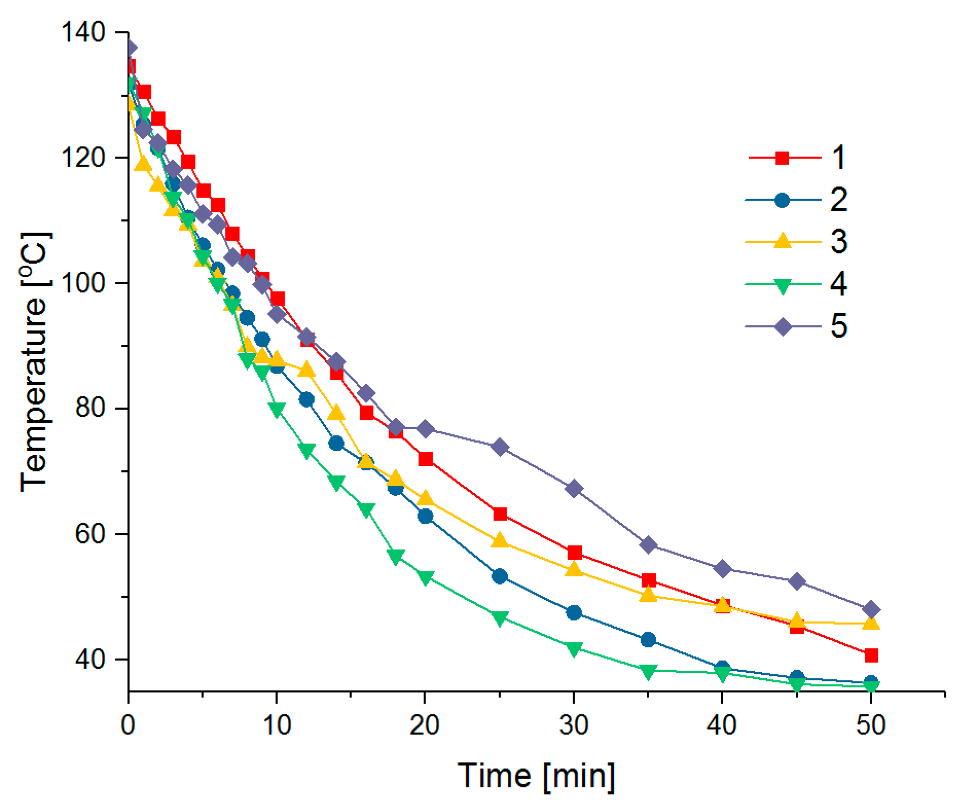
| Time (min) | Temperature (°C) | ||||
|---|---|---|---|---|---|
| 1 | 2 | 3 | 4 | 5 | |
| 0 | 134.8 | 131.8 | 128.6 | 132.1 | 137.7 |
| 1 | 130.7 | 125.4 | 119 | 127.3 | 124.6 |
| 2 | 126.4 | 121.6 | 115.6 | 121.7 | 122.5 |
| 3 | 123.5 | 116 | 111.7 | 113.8 | 118.3 |
| 4 | 119.5 | 110.6 | 109.5 | 110.4 | 115.8 |
| 5 | 115 | 106.2 | 103.6 | 104.5 | 111.2 |
| 6 | 112.6 | 102.3 | 101 | 100.1 | 109.5 |
| 7 | 108.1 | 98.5 | 96.6 | 96.7 | 104.3 |
| 8 | 104.4 | 94.6 | 90 | 88 | 103.3 |
| 9 | 100.9 | 91.2 | 88.3 | 86.1 | 99.9 |
| 10 | 97.8 | 86.9 | 87.8 | 80.2 | 95.2 |
| 12 | 91.2 | 81.6 | 86.2 | 73.6 | 91.6 |
| 14 | 85.9 | 74.6 | 79.3 | 68.5 | 87.6 |
| 16 | 79.5 | 71.5 | 71.5 | 64.2 | 82.6 |
| 18 | 76.5 | 67.5 | 68.8 | 56.7 | 77.2 |
| 20 | 72.2 | 63 | 65.6 | 53.4 | 76.9 |
| 25 | 63.4 | 53.4 | 58.9 | 46.9 | 74 |
| 30 | 57.2 | 47.6 | 54.3 | 42 | 67.4 |
| 35 | 52.8 | 43.3 | 50.3 | 38.4 | 58.4 |
| 40 | 48.8 | 38.7 | 48.6 | 38 | 54.6 |
| 45 | 45.5 | 37.2 | 46.1 | 36.2 | 52.6 |
| 50 | 40.9 | 36.4 | 45.8 | 35.8 | 48.1 |
| Ingredient | cv (J/kg·K) |
|---|---|
| Sand | 800 |
| Cement | 504 |
| Water | 4190 |
| Silicate aggregate | 1006 |
| Mafic aggregate | 990 |
| Carbonate aggregate | 920 |
| Refractory aggregate | 1750 |
| Glass fiber | 840 |
| Polypropylene fiber | 1460 |
| Steel fiber | 440 |
| Sample | Σ cv (J/kg·K) |
|---|---|
| 1 | 1017.79 |
| 2 | 765.78 |
| 3 | 1170.03 |
| 4 | 990.58 |
| 5 | 1120.15 |
| Sample | ∆T (K) | ∆Q (kJ) |
|---|---|---|
| 1 | 93.9 | 42.72 |
| 2 | 95.4 | 25.64 |
| 3 | 82.8 | 36.13 |
| 4 | 96.3 | 26.9 |
| 5 | 89.6 | 59.11 |
| Sample | b (kJ/m3·K) | bmax (MJ/m3) |
|---|---|---|
| 1 | 2167.89 | 203.57 |
| 2 | 1347.77 | 128.50 |
| 3 | 2468.76 | 204.43 |
| 4 | 1485.87 | 143.01 |
| 5 | 2419.52 | 216.83 |
| Sample | P (W) |
|---|---|
| 1 | 14.24 |
| 2 | 8.55 |
| 3 | 12.04 |
| 4 | 8.97 |
| 5 | 19.70 |
| Sample Symbol | Maturation Time (days) | ||
|---|---|---|---|
| 1 | 7 | 28 | |
| Mechanical (MPa) | |||
| 1 | 8.5 | 9.9 | 12.3 |
| 2 | 3.5 | 4.3 | 5 |
| 3 | 7.4 | 10 | 13.2 |
| 4 | 2.9 | 4.1 | 4.7 |
| 5 | 1.8 | 3 | 4.8 |
Publisher’s Note: MDPI stays neutral with regard to jurisdictional claims in published maps and institutional affiliations. |
© 2021 by the authors. Licensee MDPI, Basel, Switzerland. This article is an open access article distributed under the terms and conditions of the Creative Commons Attribution (CC BY) license (http://creativecommons.org/licenses/by/4.0/).
Share and Cite
Stempkowska, A.; Mastalska-Popławska, J.; Izak, P.; Wójcik, Ł.; Gawenda, T.; Karbowy, M. Research on the Thermal Properties of Fireplace Concrete Materials Containing Various Mineral Aggregates Enriched by Organic and Inorganic Fibers. Materials 2021, 14, 904. https://doi.org/10.3390/ma14040904
Stempkowska A, Mastalska-Popławska J, Izak P, Wójcik Ł, Gawenda T, Karbowy M. Research on the Thermal Properties of Fireplace Concrete Materials Containing Various Mineral Aggregates Enriched by Organic and Inorganic Fibers. Materials. 2021; 14(4):904. https://doi.org/10.3390/ma14040904
Chicago/Turabian StyleStempkowska, Agata, Joanna Mastalska-Popławska, Piotr Izak, Łukasz Wójcik, Tomasz Gawenda, and Marzena Karbowy. 2021. "Research on the Thermal Properties of Fireplace Concrete Materials Containing Various Mineral Aggregates Enriched by Organic and Inorganic Fibers" Materials 14, no. 4: 904. https://doi.org/10.3390/ma14040904