
Experimental Study of High Performance Synchronous Grouting Materials Prepared with Clay

Abstract
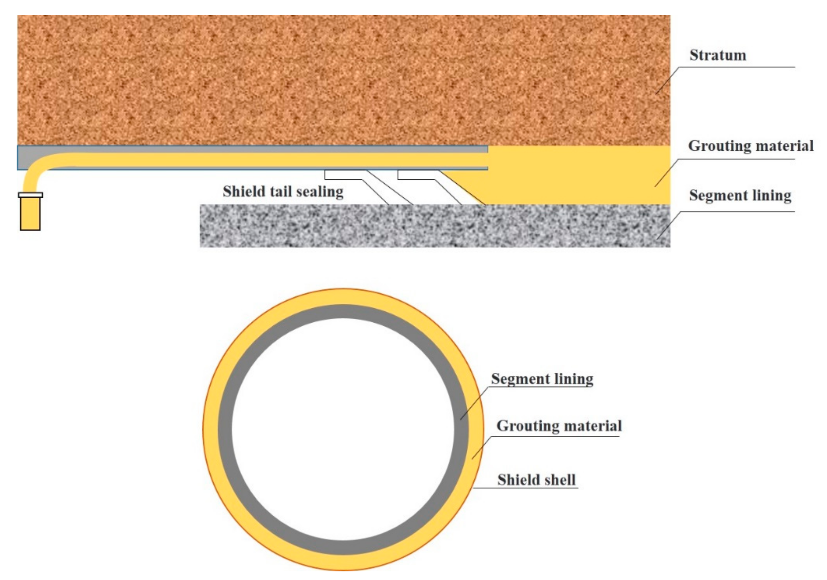
:1. Introduction
2. Materials and Methods
2.1. Materials
2.2. Mixing and Testing Procedures
3. Results and Discussion
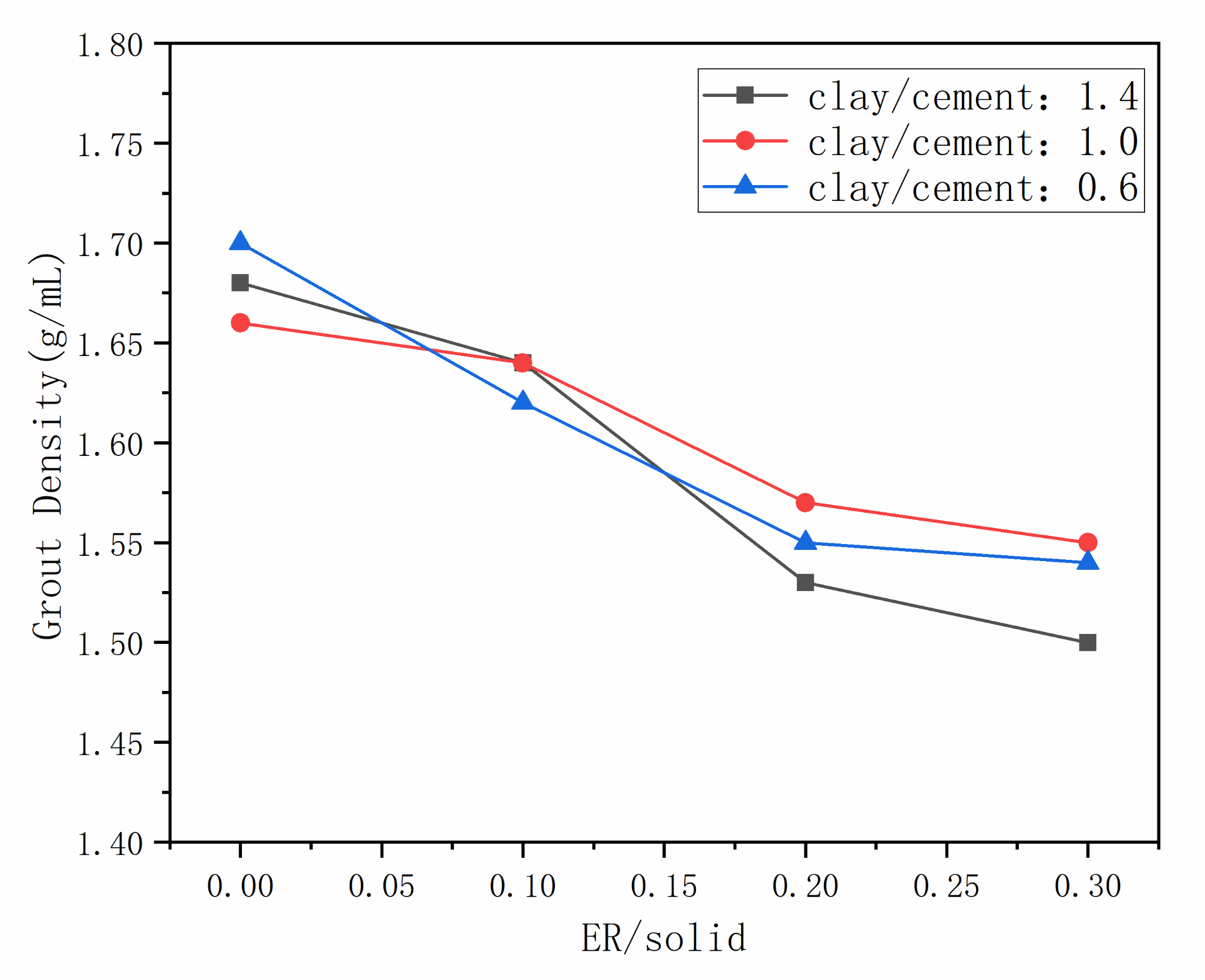
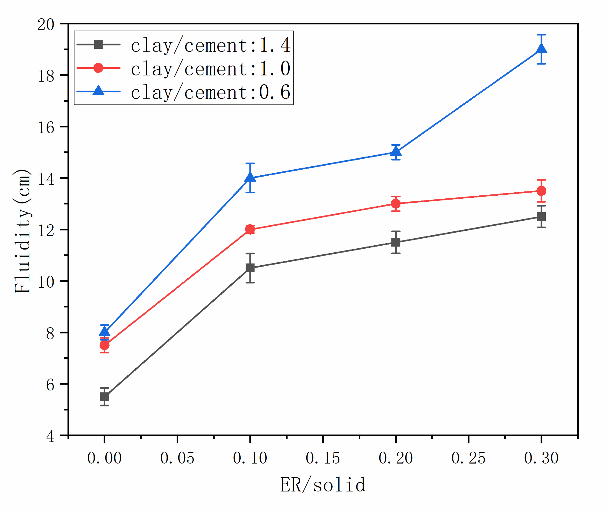
3.1. Workability
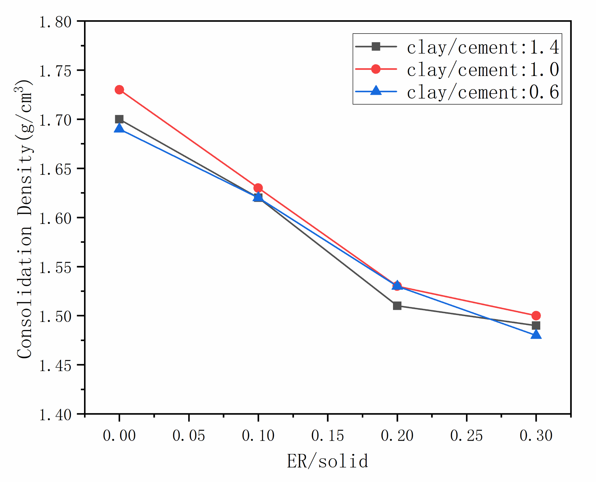
3.2. Stability
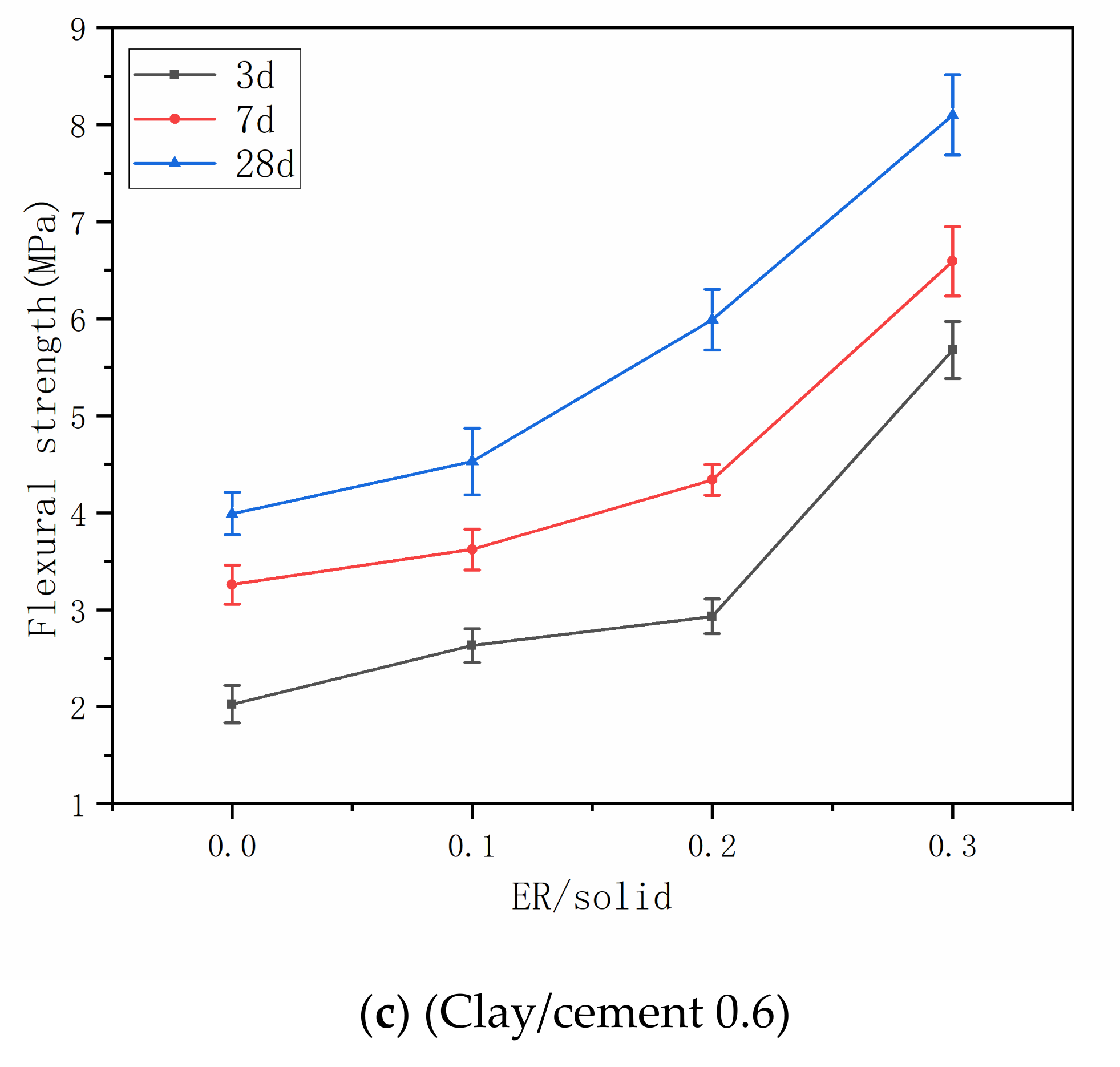
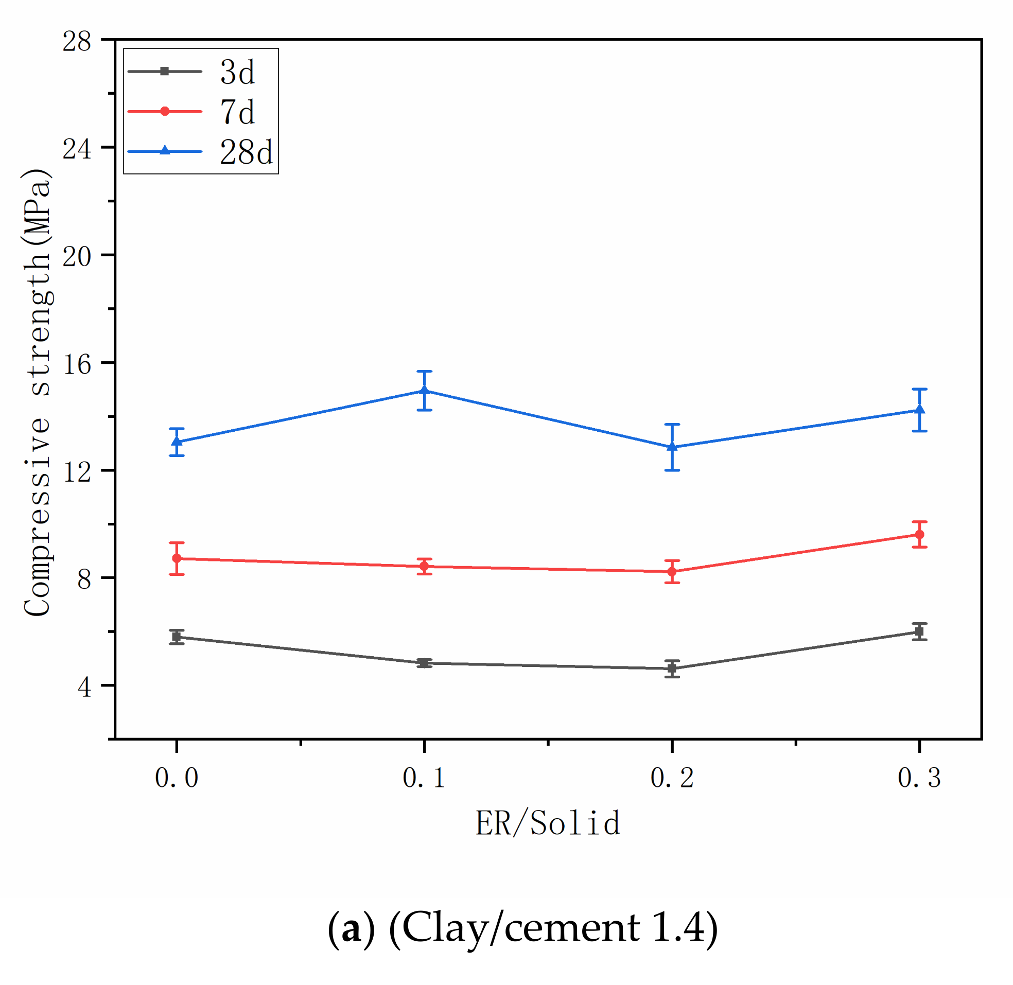
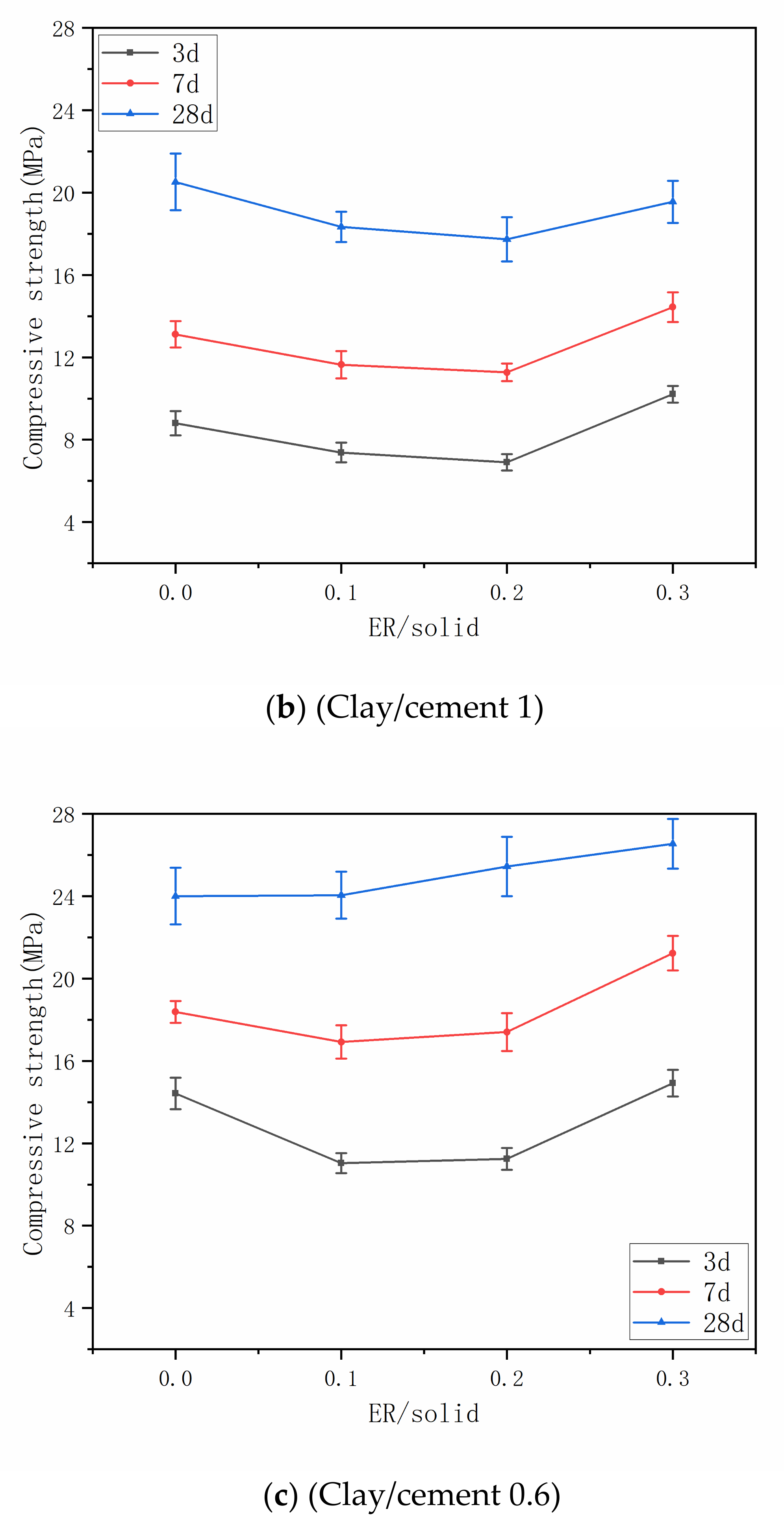
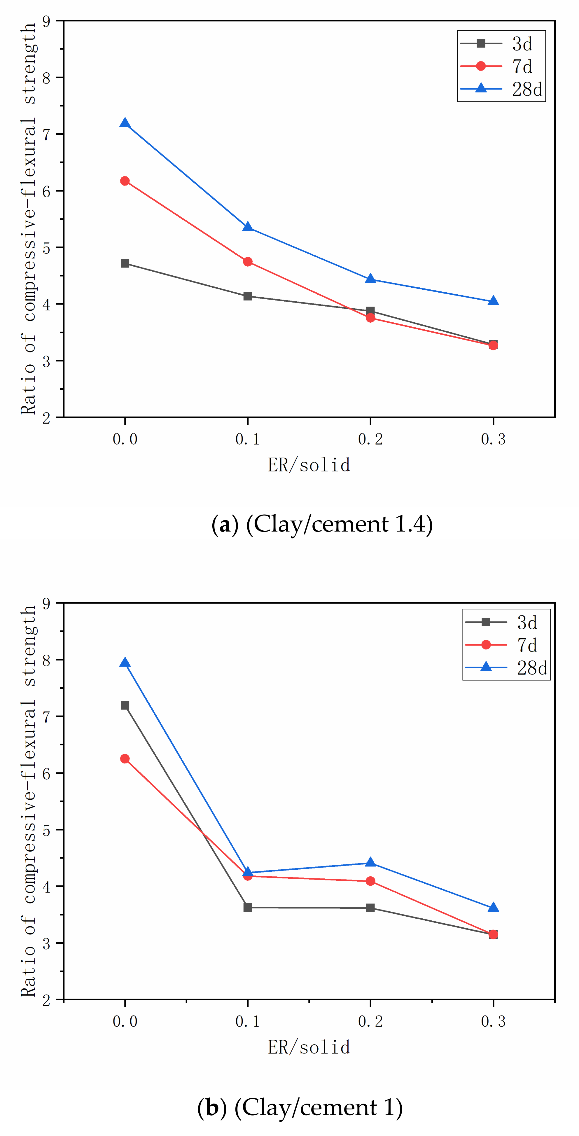
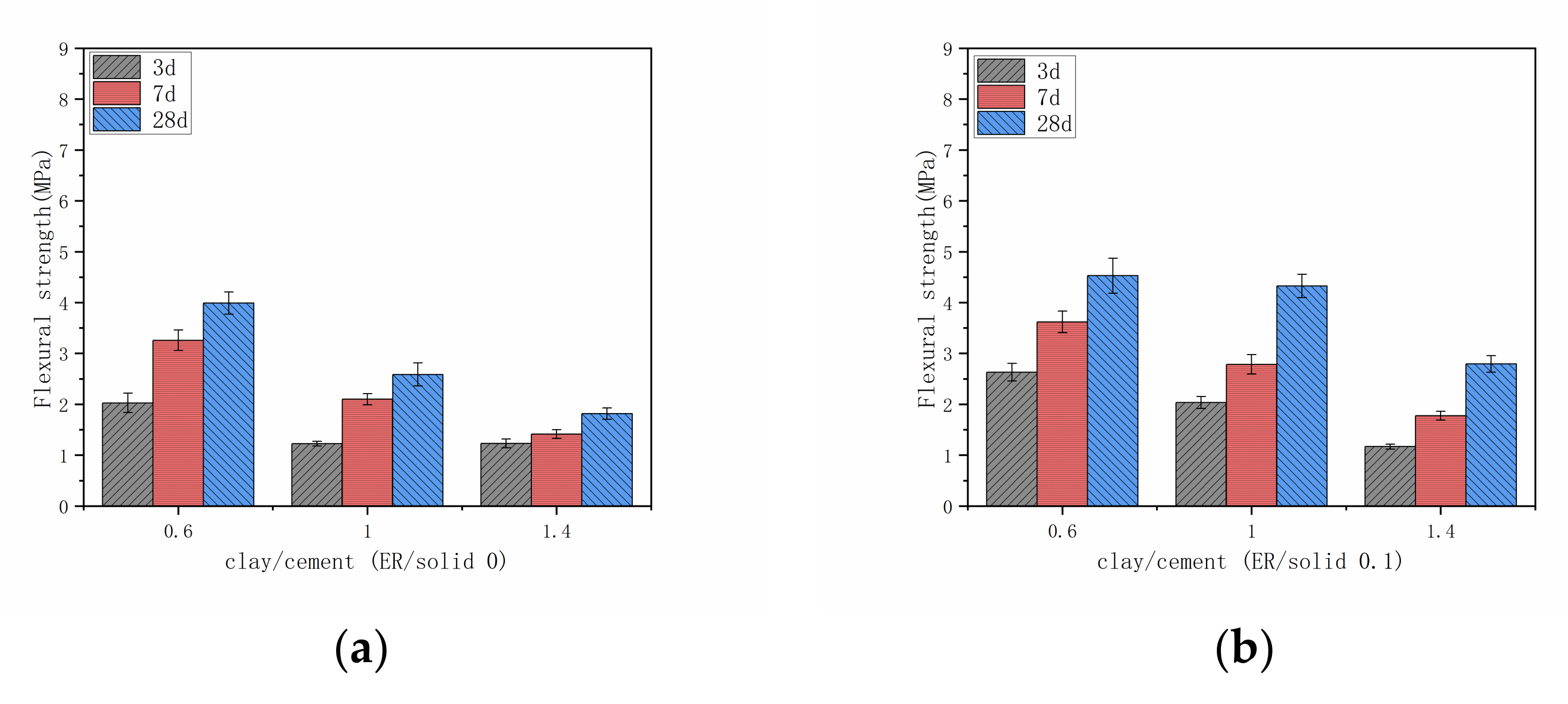
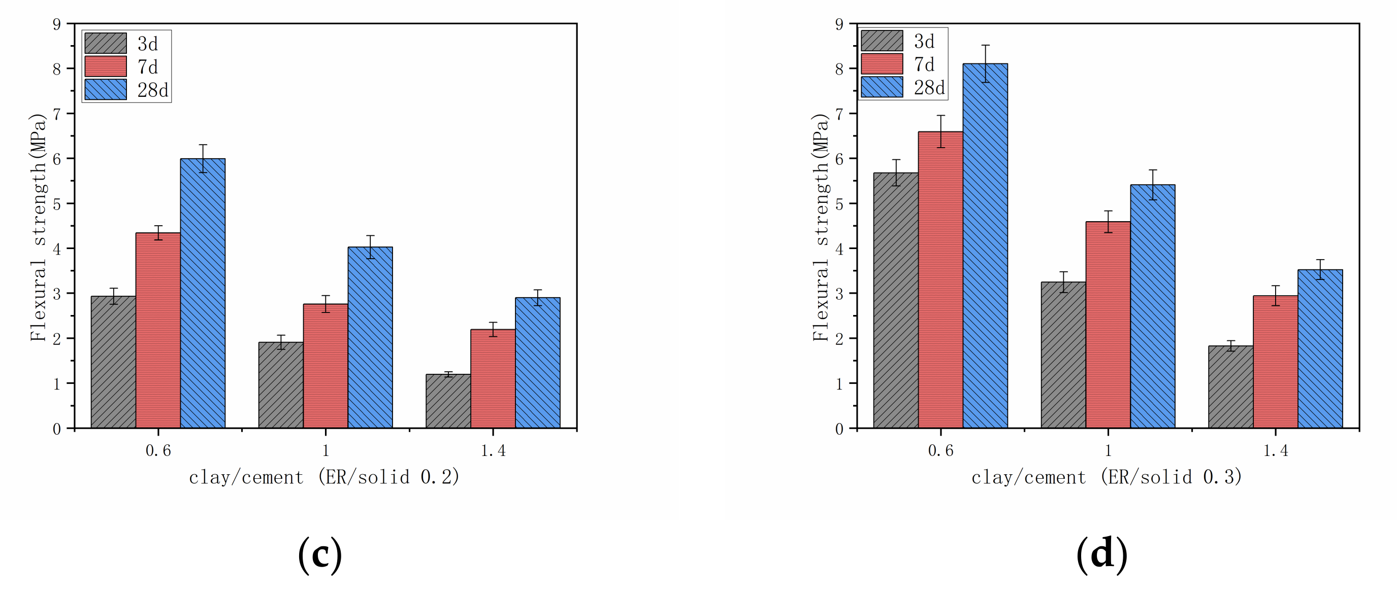
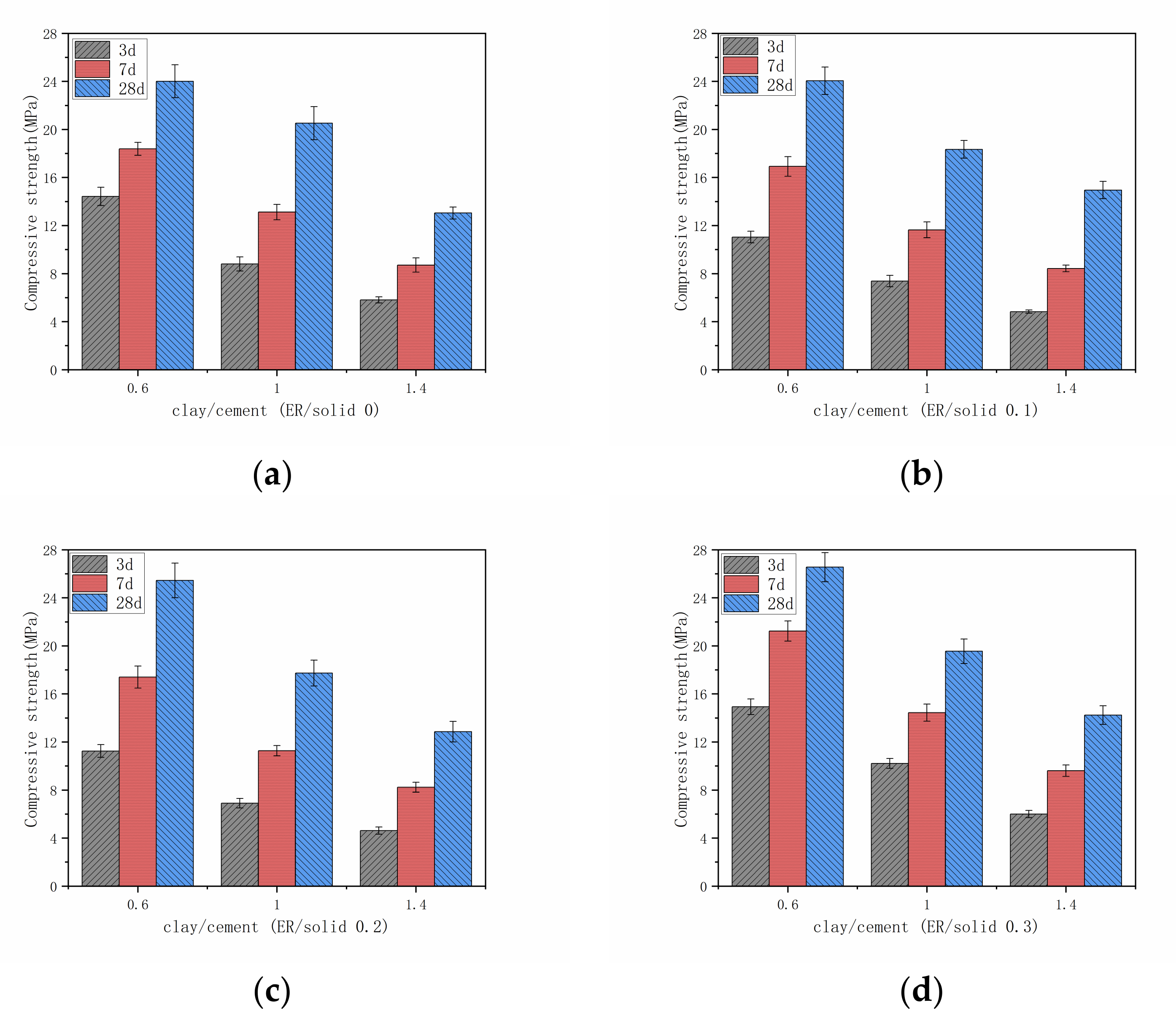
3.3. Mechanical Properties
3.4. Microstructure Analysis
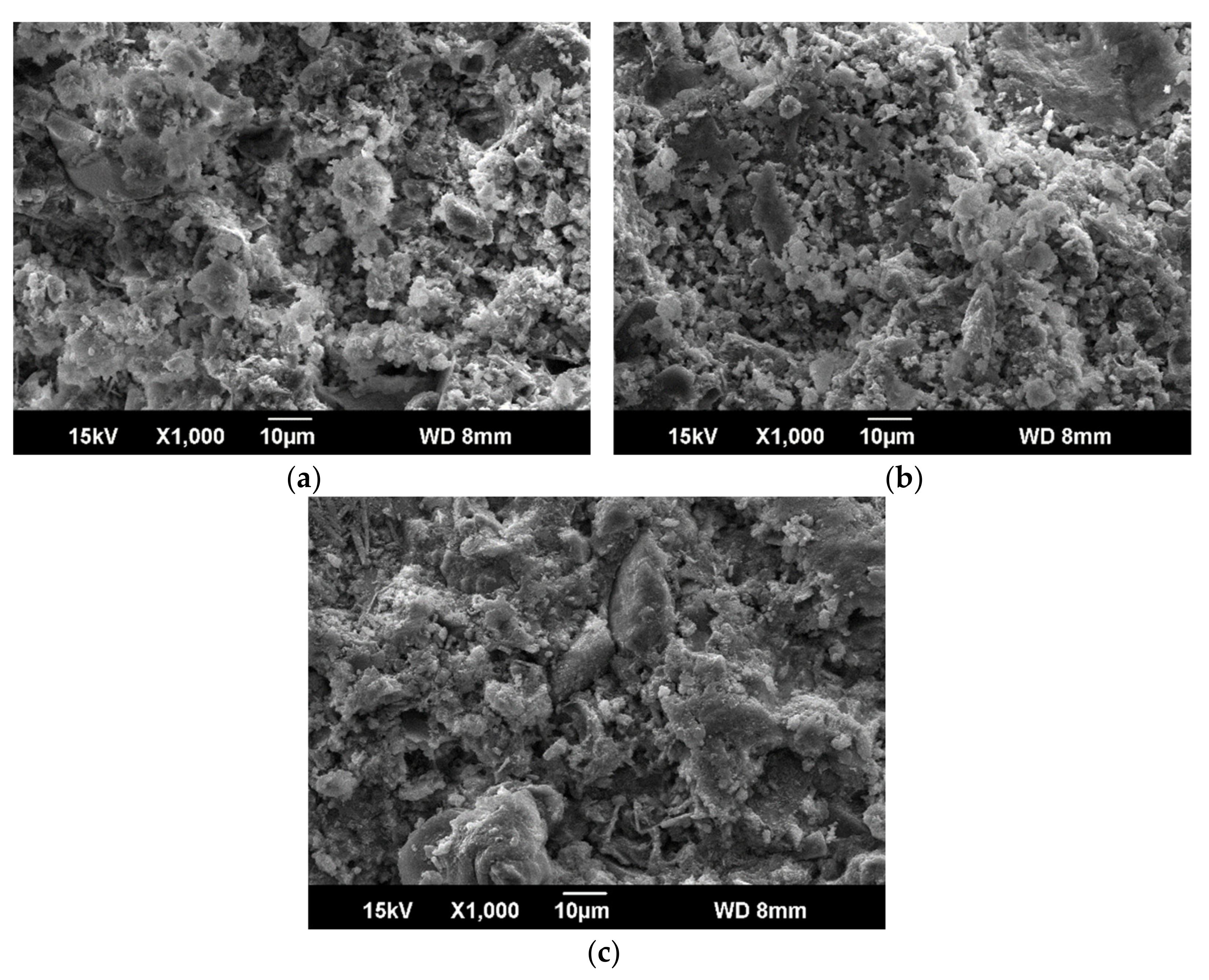
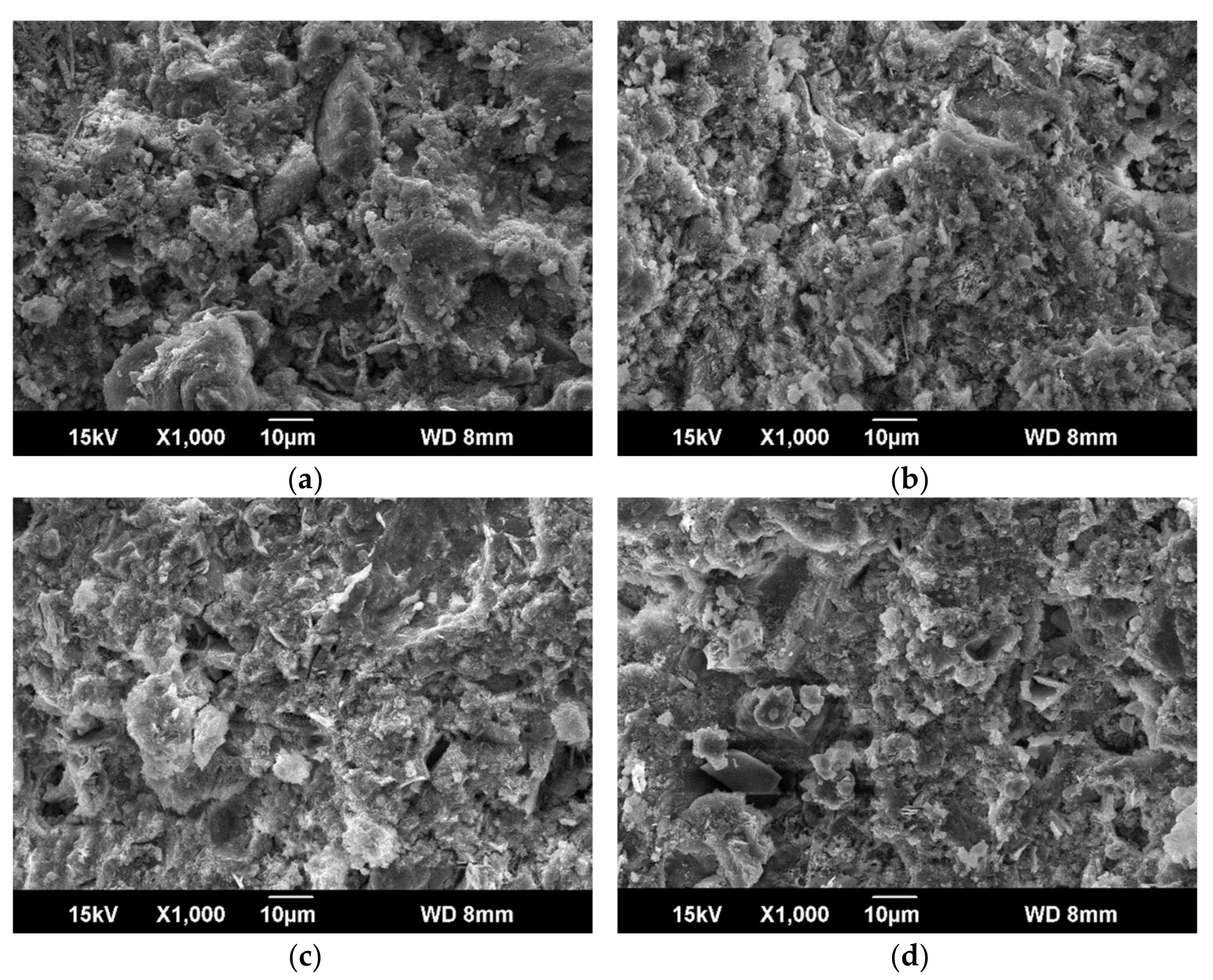
3.4.1. SEM Analyses
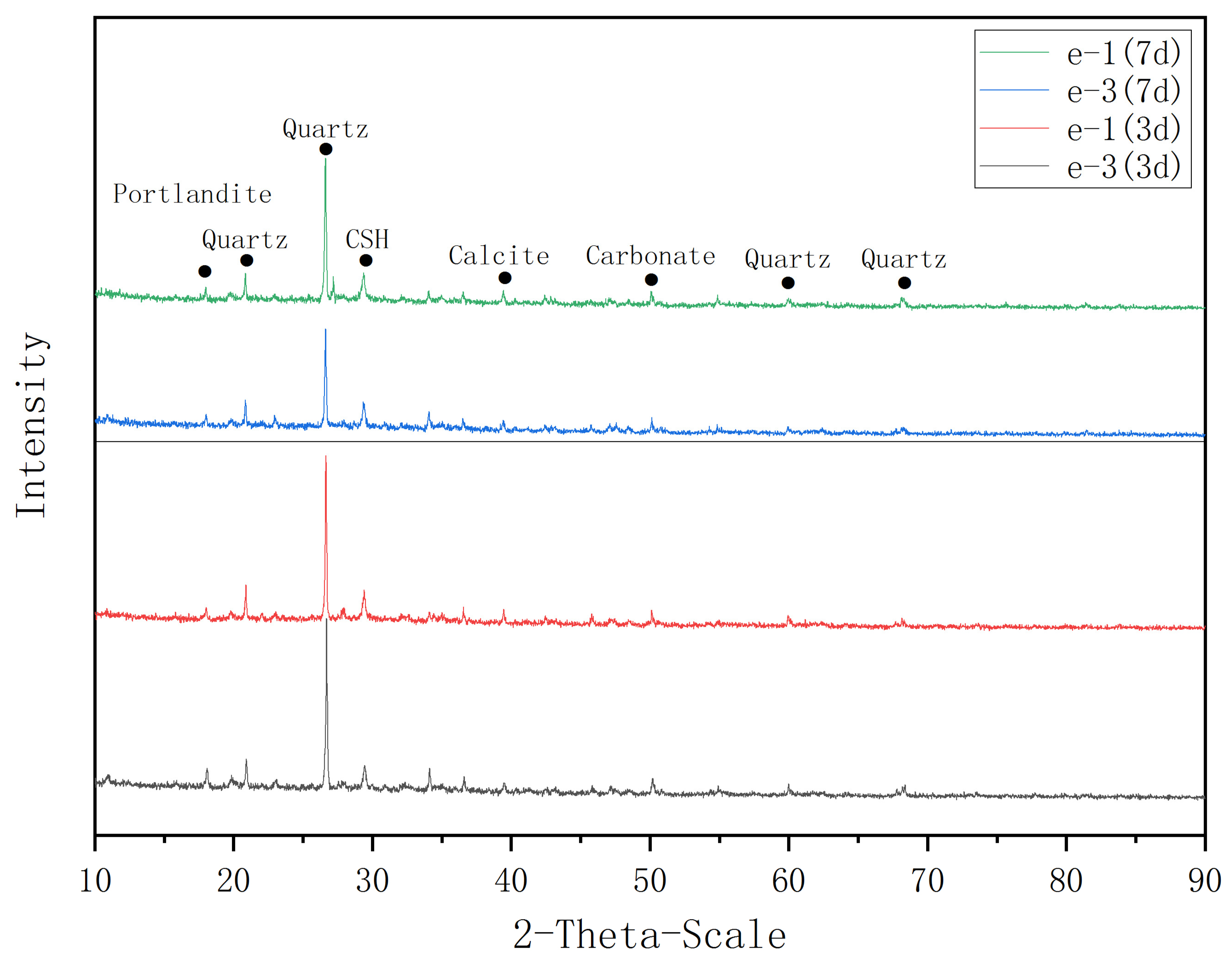
3.4.2. XRD Analyses
4. Conclusions
- (1)
- The addition of waterborne epoxy resin can reduce the density of the grout, improve the fluidity of the grout, the grout is stable with high stone rate.
- (2)
- The mechanical properties of grout increased with the increase of epoxy resin content, but decreased with the increase of clay content.
- (3)
- Microstructure test showed that the proper amount of epoxy resin mixed into cement clay slurry can combine well with hydration products and form a network structure, which can not only improve the hydration products, but also connect clay particles and hydration products, absorb energy of external load, and delay or restrain the development of the cracks, so as to enhance the toughness of the grout.
Author Contributions
Funding
Data Availability Statement
Conflicts of Interest
References
- Sharghi, M.; Chakeri, H.; Ozcelik, Y. Investigation into the effects of two component grout properties on surface settlements. Tunn. Undergr. Space Technol. 2017, 63, 205–216. [Google Scholar] [CrossRef]
- Shah, R.; Lavasan, A.A.; Peila, D.; Todaro, C.; Luciani, A.; Schanz, T. Numerical Study on Backfilling the Tail Void Using a Two-Component Grout. J. Mater. Civil Eng. 2018, 30, 04018003. [Google Scholar] [CrossRef]
- Sharghi, M.; Chakeri, H.; Afshin, H.; Ozcelik, Y. An Experimental Study of the Performance of Two-Component Backfilling Grout Used behind the Segmental Lining of a Tunnel-Boring Machine. J. Test. Eval. 2018, 46, 20160617. [Google Scholar] [CrossRef]
- Pelizza, S.; Peila, D.; Borio, L.; Negro, E.; Schulkins, R.; Boscaro, A. Analysis of the Performance of Two Component Back-Filling Grout in Tunnel Boring Machines Operating under Face Pressure. Available online: https://www.tunnelcanada.ca/members/documents/2010/WTC2010/pdf/fin00148.pdf (accessed on 31 January 2020).
- Zhu, L.; Bai, T. The comparison of Grouting Material Proportion of Earth Pressure balance Shield Tunneling in Shanghai. Undergr. Eng. Tunn. 1993, 42–48. (In Chinese). Available online: https://xueshu.baidu.com/usercenter/paper/show?paperid=ff911b1acd4fbfb030d5d9d5623a903e&site=xueshu_se (accessed on 22 January 2020).
- Xiao, C.; Zhang, Q. Study on the Experiment of Grouting Material Proportion. J. Yangtze Univ. Nat. Sci. Ed. 2013, 10, 107–109. (In Chinese) [Google Scholar]
- Ye, F.; Mao, J.; Ji, M.; Sun, C.; Chen, Z. Research Status and Development Trend of Back-Filled Grouting of Shield Tunnels. Tunn. Constr. 2015, 35, 739–752. [Google Scholar]
- Wang, H.; Tian, K.; Ding, Q.; Chen, Y.; Hu, S. The Development of Underwater Disperse Mortar for Tail Void Grouting. China Concr. Cem. Prod. 2006, 6, 32–34. (In Chinese) [Google Scholar]
- Peng, B.; Tian, K.; Ding, Q. Polymer Modified Cement Mortar Used in Synchronous Grouting of Shield Tunnelling. Concrete 2008, 7, 97–99, 102. (In Chinese) [Google Scholar]
- Su, H.; Li, Z.; Wang, Z. Grouting Experiment of Shield Tunnel Crossing Yellow River in Middle Route of the South-to-North Water Diversion Project. South-to-North Water Transf. Water Sci. Technol. 2008, 1, 28–32. (In Chinese) [Google Scholar]
- Peila, D.; Chieregato, A.; Martinelli, D.; Oñate Salazar, C.; Shah, R.; Boscaro, A.; Negro, E.D.; Picchio, A. Long Term Behavior of Two Component Back-Fill Grout Mix Used in Full Face Mechanized Tunneling. Geoing. Ambient. Min. 2015, 144, 57–63. [Google Scholar]
- Zhang, C.; Yang, J.; Fu, J.; Wang, S.; Yin, J.; Xie, Y. Recycling of Discharged Soil From EPB Shield Tunnels as a Sustainable Raw Material for Synchronous Grouting. J. Clean. Prod. 2020, 268, 121947. [Google Scholar] [CrossRef]
- Li, H.; Xie, F.; Xuan, H.; Sheng, D.; Hu, T.; Wang, X.; Xie, Z. Phosphate Removal by Using Magnesium Oxide/Constructionwaste of Subway Composite Ceramsite. Appl. Chem. Ind. 2015, 44, 1581–1585. (In Chinese) [Google Scholar]
- Zhang, T.; Rong, H.; Liu, Z.; Wang, H.; Zhang, L.; Di, Z.; Song, W.; Qi, Z.; Li, X. Research On Preparation And Properties Of Muck Ce-Ramsite for 900 Density Level. New Build. Mater. 2017, 44, 109–113. (In Chinese) [Google Scholar]
- Grohs, H. Cost-Efficient Regeneration of Bore Slurry for Driving of the Weser Tunnel. Aufbereit. Tech. 2002, 43, 30–37. [Google Scholar]
- Jiang, J.; Yin, B. Research on Development of New Wall Materials by Shield Muck. Brick-Tile 2019, 3, 45–48. (In Chinese) [Google Scholar]
- Hao, T.; Li, X.; Leng, F.; Wang, S. Synchronous Grouting Materials for Shield Slag in silty Clay of Zhengzhou Metro. J. Chang. Univ. Nat. Sci. Ed. 2020, 40, 53–62. (In Chinese) [Google Scholar]
- Liang, J. Study on the Ratio Optimization of Grouting Material and the Deformation Characteristics of the Grouting Material behind the Shield Tunnel Wall. Master’s Thesis, Hohai University, Nanjing, China, 2006. (In Chinese). [Google Scholar]
- Zhong, X.; Zuo, J.; Liu, Q.; Han, Y. Reuse of Excavated Fine Sand for Back Grouting of Shield Tunneling. Rock Soil Mech. 2008, 29 (Suppl. S1), 293–296. (In Chinese) [Google Scholar]
- Zhou, S.; Li, X.; Ji, C.; Xiao, J. Back-Fill Grout Experimental Test for Discharged Soils Reuse of the Large-Diameter Size Slurry Shield Tunnel. KSCE J. Civ. Eng. 2017, 21, 1–9. [Google Scholar] [CrossRef]
- Zhang, Y.; Xia, P.; Wei, D.; Jiang, T.; Chen, X.; Lu, S. Slurry Treatment and Waste Muck Recycling Use in Construction of Weisanlu Yangtze River Crossing Tunnel in Nanjing. Tunn. Constr. 2015, 35, 1229–1233. (In Chinese) [Google Scholar]
- Xu, K. The Research and Application on High-Performance Grouting Made by Shield Sediment. Master’s Thesis, Wuhan University of Technology, Wuhan, China, 2011. (In Chinese). [Google Scholar]
- Yang, Z.; He, Z.; Wu, K. Study of Application of Waste Slurry to Backfilled Grouting of Shield Tunnel. Tunn. Constr. 2017, 37, 985–989. (In Chinese) [Google Scholar]
- Zhou, D.; Li, M. Experimental Study on New Materials of Synchronic Grouting in Shield Tunneling. Undergr. Eng. Tunn. 2002, 1, 10–13. (In Chinese) [Google Scholar]
- Standardization Administration of the People’s Republic of China. GB/T 176-2017 Methods of Chemical Analysis of Cement; Standards; Press of China: Beijing, China, 2017. [Google Scholar]
- National Energy Administration. SY/T 5163-2010 Analysis Method for Clay Minerals and Ordinary Non-Clay Minerals in Sedimentary Rocks by the X-ray Diffraction; Petroleum Industry Press: Beijing, China, 2010. [Google Scholar]
- Anagnostopoulos, C.A. Strength Properties of an Epoxy Resin and Cement-Stabilized Silty Clay Soil. Appl. Clay Sci. 2015, 114, 517–529. [Google Scholar] [CrossRef]
- He, S.; Lai, J.; Wang, L.; Wang, K. A Literature Review on Properties and Applications of Grouts for Shield Tunnel. Constr. Build. Mater. 2020, 239, 117782. [Google Scholar] [CrossRef]
- General Administration of Quality Supervision, Inspection and Quarantine of the People’s Republic of China. GB/T 19139-2003 Procedure for Testing Well Cements; Standards Press of China: Beijing, China, 2003. [Google Scholar]
- General Administration of Quality Supervision, Inspection and Quarantine of the People’s Republic of China. GB/T 8077-2000 Methods for Testing Uniformity of Concrete Admixture; Standards Press of China: Beijing, China, 2000. [Google Scholar]
- General Administration of Quality Supervision, Inspection and Quarantine of the People’s Republic of China. GB/T 17671-1999 Method of Testing cements-Determination of Strength; Standards Press of China: Beijing, China, 1999. [Google Scholar]
- Ohama, Y. Recent Progress in Concrete-Polymer Composites. Adv. Cem. Based Mater. 1997, 5, 31–40. [Google Scholar] [CrossRef]
- Su, Z.; Bijen, J.M.J.M.; Larbi, J.A. Influence of Polymer Modification on the Hydration of Portland Cement. Cem. Concr. Res. 1991, 21, 242–250. [Google Scholar] [CrossRef]
- Anagnostopoulos, C.A.; Sapidis, G.; Papastergiadis, E. Fundamental Properties of Epoxy Resin-Modified Cement Grouts. Constr. Build. Mater. 2016, 125, 184–195. [Google Scholar] [CrossRef]
- Zhang, C.; Yang, J.; Ou, X.; Fu, J.; Xie, Y.; Liang, X. Clay Dosage and Water/Cement Ratio of Clay-Cement Grout for Optimal Engineering Performance. Appl. Clay Sci. 2018, 163, 312–318. [Google Scholar] [CrossRef]
- Barluenga, G.; Hernández-Olivares, F. SBR Latex Modified Mortar Rheology and Mechanical Behaviour. Cem. Concr. Res. 2004, 34, 527–535. [Google Scholar] [CrossRef]
- Jenni, A.; Zurbriggen, R.; Holzer, L.; Herwegh, M. Changes in Microstructures and Physical Properties of Polymer-Modified Mortars during Wet Storage. Cem. Concr. Res. 2006, 36, 79–90. [Google Scholar] [CrossRef]
- Huang, Z.; Chen, W.; Li, Q.; Wang, M.; Fan, J. Mechanical Properties and Microstructure of Waterborne Epoxy Resin Modified Cement Mortar. Bull. Chin. Ceram. Soc. 2017, 36, 2530–2535. (In Chinese) [Google Scholar]
- Pusch, R.; Yong, R. Water Saturation and Retention of Hydrophilic Clay Buffer—Microstructural Aspects. Appl. Clay Sci. 2003, 23, 61–68. [Google Scholar] [CrossRef]
- Al-Malah, K.; Abu-Jdayil, B. Clay-Based Heat Insulator Composites: Thermal and Water Retention Properties. Appl. Clay Sci. 2007, 37, 90–96. [Google Scholar] [CrossRef]
- Vipulanandan, C.; Sunder, S. Effects of Meta-Kaolin Clay on the Working and Strength Properties of Cement Grouts. In Proceedings of the Fourth International Conference on Grouting and Deep Mixing, New Orleans, LA, USA, 15–18 February 2012. [Google Scholar]
- Zhang, G.; Liu, J.; Li, Y.; Liang, J. A Pasty Clay–Cement Grouting Material for Soft and Loose Ground under Groundwater Conditions. Adv. Cem. Res. 2017, 29, 54–62. [Google Scholar] [CrossRef]
- Gao, L. Effects of Polymer on Properties of Cement-Based Composite. Master’s Thesis, Hebei Polytechnic University, Tangshan, China, 2005. (In Chinese). [Google Scholar]
- Chew, S.H.; Kamruzzaman, A.H.M.; Lee, F.H. Physicochemical and Engineering Behavior of Cement Treated Clays. J. Geotech. Geoenviron. Eng. 2004, 130, 696–706. [Google Scholar] [CrossRef]
- Lee, F.H.; Lee, Y.; Chew, S.H.; Yong, K.Y. Strength and Modulus of Marine Clay-Cement Mixes. J. Geotech. Geoenviron. Eng. 2005, 131, 178–186. [Google Scholar] [CrossRef]
- Wang, X. SEM Study of Hardening Processes of Clay-Hardening Grouts. Chin. J. Geotech. Eng. 1999, 1, 37–43. (In Chinese) [Google Scholar]
- Wegmann, A. Chemical Resistance of Waterborne Epoxy/Amine Coatings. Prog. Org. Coat. 1997, 32, 213–239. [Google Scholar] [CrossRef]
- Aggarwal, L.K.; Thapliyal, P.C.; Karade, S.R. Properties of Polymer-Modified Mortars Using Epoxy and Acrylic Emulsions. Constr. Build. Mater. 2007, 21, 379–383. [Google Scholar] [CrossRef]


| Constituents | CaO | Al2O3 | SiO2 | Fe2O3 | MgO | SO3 | TiO2 | L.O.I. |
| % | 68.50 | 1.28 | 18.40 | 2.73 | 5.48 | 2.45 | 1.04 | 0.12 |
| Constituents | CaO | Al2O3 | SiO2 | Fe2O3 | MgO | SO3 | K2O | L.O.I. |
| % | 1.50 | 17.80 | 68.40 | 6.73 | 2.96 | 0.45 | 2.04 | 0.12 |
| Constituents | Illite/Smectite Mixed-Layer | Illite | Kaolinite | Ratio of Mixed-Layer |
|---|---|---|---|---|
| % | 56.00 | 19.00 | 25.00 | 50.00 |
| Designation | Proportion (Solid: Clay/Cement) | Proportion (Epoxy Resin (ER)/Solid) |
|---|---|---|
| e-1 | 1.4 | 0 |
| e-2 | 1.4 | 0.1 |
| e-3 | 1.4 | 0.2 |
| e-4 | 1.4 | 0.3 |
| e-5 | 1.0 | 0 |
| e-6 | 1.0 | 0.1 |
| e-7 | 1.0 | 0.2 |
| e-8 | 1.0 | 0.3 |
| e-9 | 0.6 | 0 |
| e-10 | 0.6 | 0.1 |
| e-11 | 0.6 | 0.2 |
| e-12 | 0.6 | 0.3 |
| Designation | e-1 | e-2 | e-3 | e-4 | e-5 | e-6 | e-7 | e-8 | e-9 | e-10 | e-11 | e-12 |
| Initial setting time (min) | 325 | 332 | 334 | 352 | 293 | 326 | 330 | 347 | 268 | 279 | 294 | 322 |
| Final setting time (min) | 560 | 539 | 541 | 547 | 471 | 509 | 527 | 532 | 451 | 468 | 496 | 514 |
| Designation | e-1 | e-2 | e-3 | e-4 | e-5 | e-6 | e-7 | e-8 | e-9 | e-10 | e-11 | e-12 |
|---|---|---|---|---|---|---|---|---|---|---|---|---|
| Bleeding rate (%) | 0 | 0.5 | 0 | 0 | 0 | 1 | 0 | 0 | 0.5 | 1 | 1 | 0 |
| Stone rate (%) | 99.4 | 99.1 | 99.7 | 99.3 | 99.4 | 99.2 | 99.4 | 99.3 | 99.4 | 98.6 | 98.6 | 97.8 |
Publisher’s Note: MDPI stays neutral with regard to jurisdictional claims in published maps and institutional affiliations. |
© 2021 by the authors. Licensee MDPI, Basel, Switzerland. This article is an open access article distributed under the terms and conditions of the Creative Commons Attribution (CC BY) license (http://creativecommons.org/licenses/by/4.0/).
Share and Cite
Cui, Y.; Tan, Z. Experimental Study of High Performance Synchronous Grouting Materials Prepared with Clay. Materials 2021, 14, 1362. https://doi.org/10.3390/ma14061362
Cui Y, Tan Z. Experimental Study of High Performance Synchronous Grouting Materials Prepared with Clay. Materials. 2021; 14(6):1362. https://doi.org/10.3390/ma14061362
Chicago/Turabian StyleCui, Ying, and Zhongsheng Tan. 2021. "Experimental Study of High Performance Synchronous Grouting Materials Prepared with Clay" Materials 14, no. 6: 1362. https://doi.org/10.3390/ma14061362