
Failure Mechanism of Hybrid Steel Beams with Trapezoidal Corrugated-Web Non-Welded Inclined Folds


Abstract
:1. Introduction
2. Research Objectives
- To test a trapezoidal SBCW hybrid section until failure under in-plane bending and shear
- To investigate the performance of a hybrid SBCW with various HF lengths under bending and constant shear force throughout the beam length
- To experimentally determine whether the non-welding of the IFs can affect the failure mechanism and capacity of hybrid SBCWs
- Eliminating the failure, this might exist because of the flange local buckling, by using a very limited number of stiffeners in a certain place
3. Experimental Programme
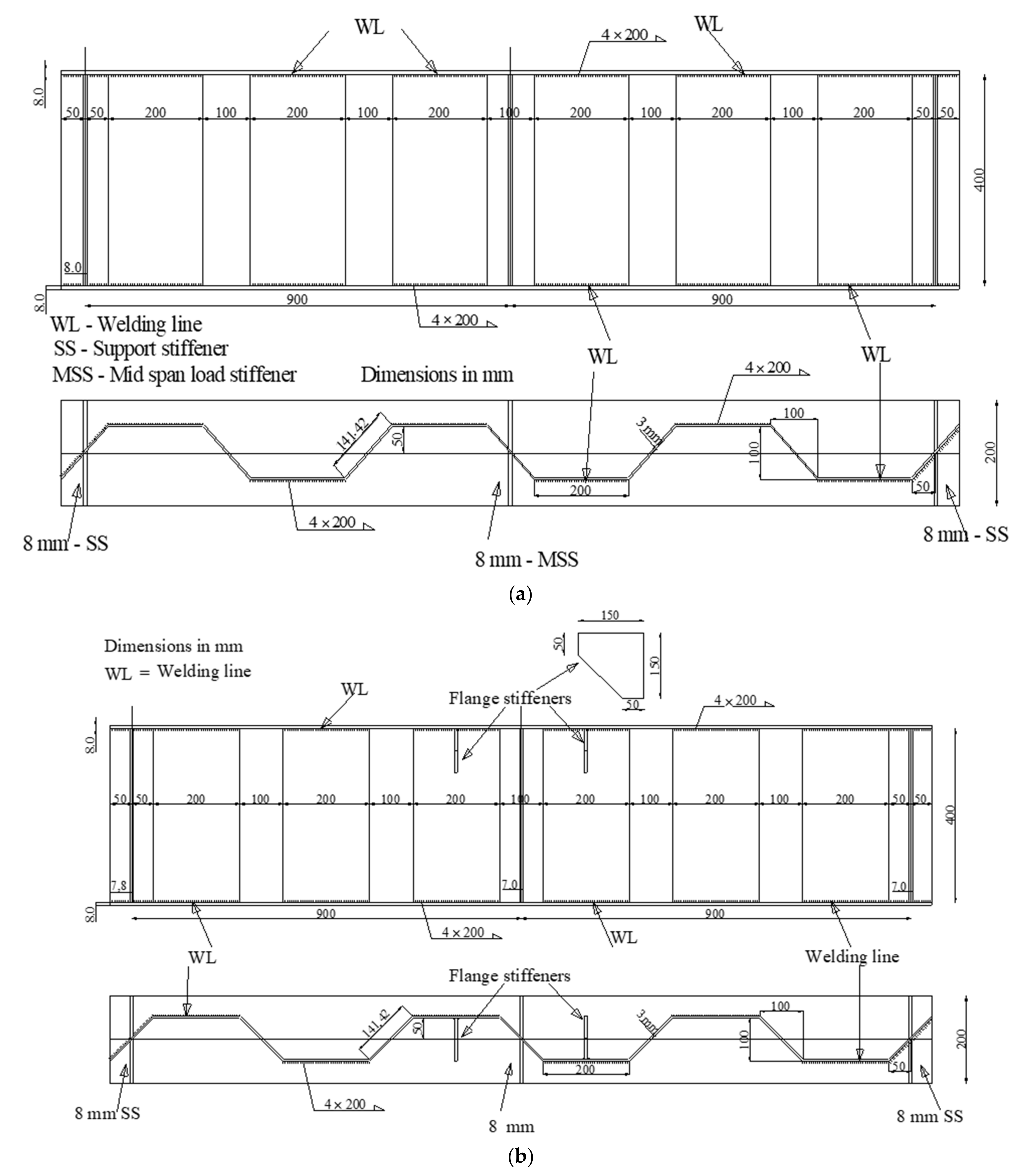
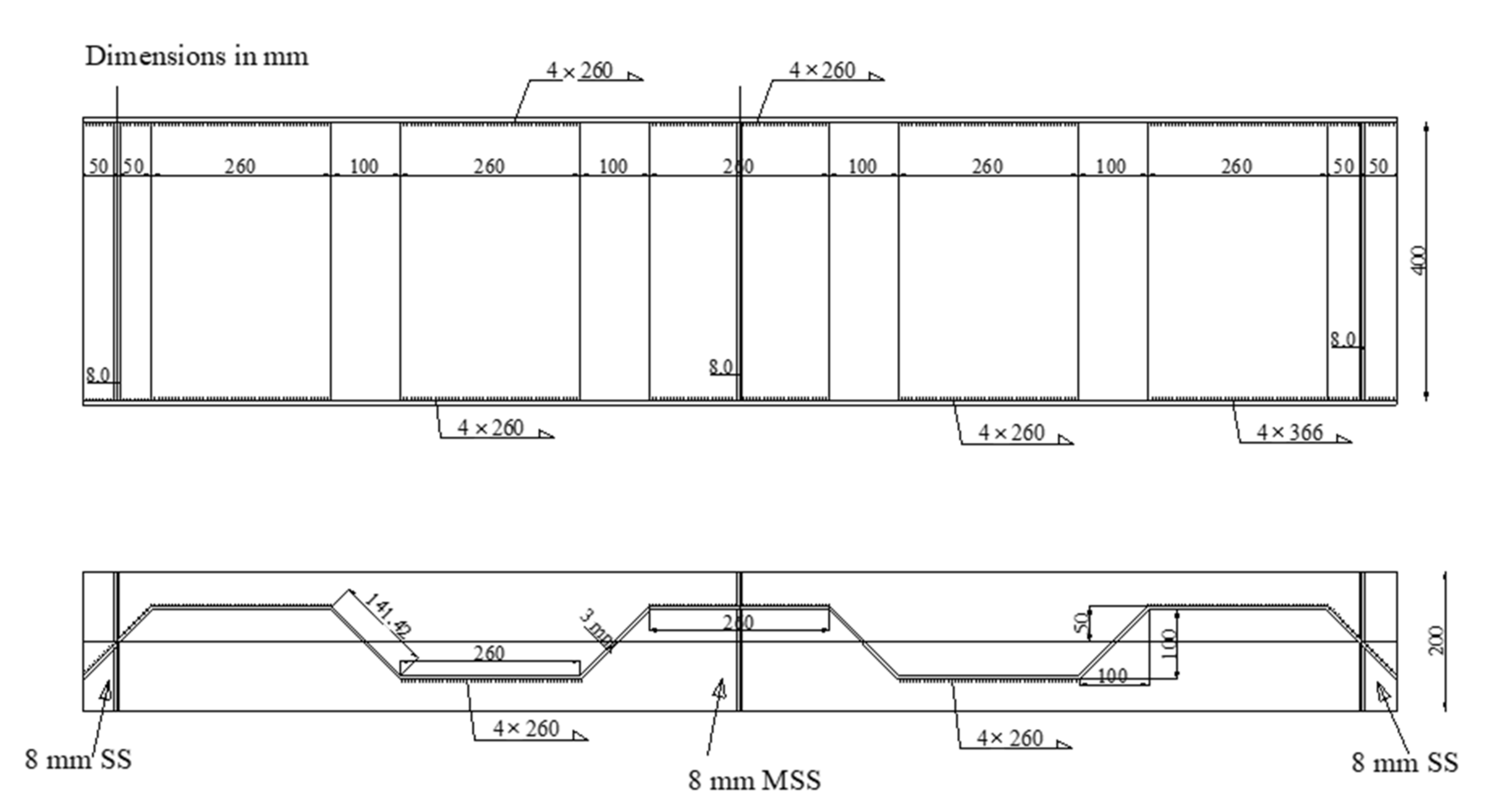
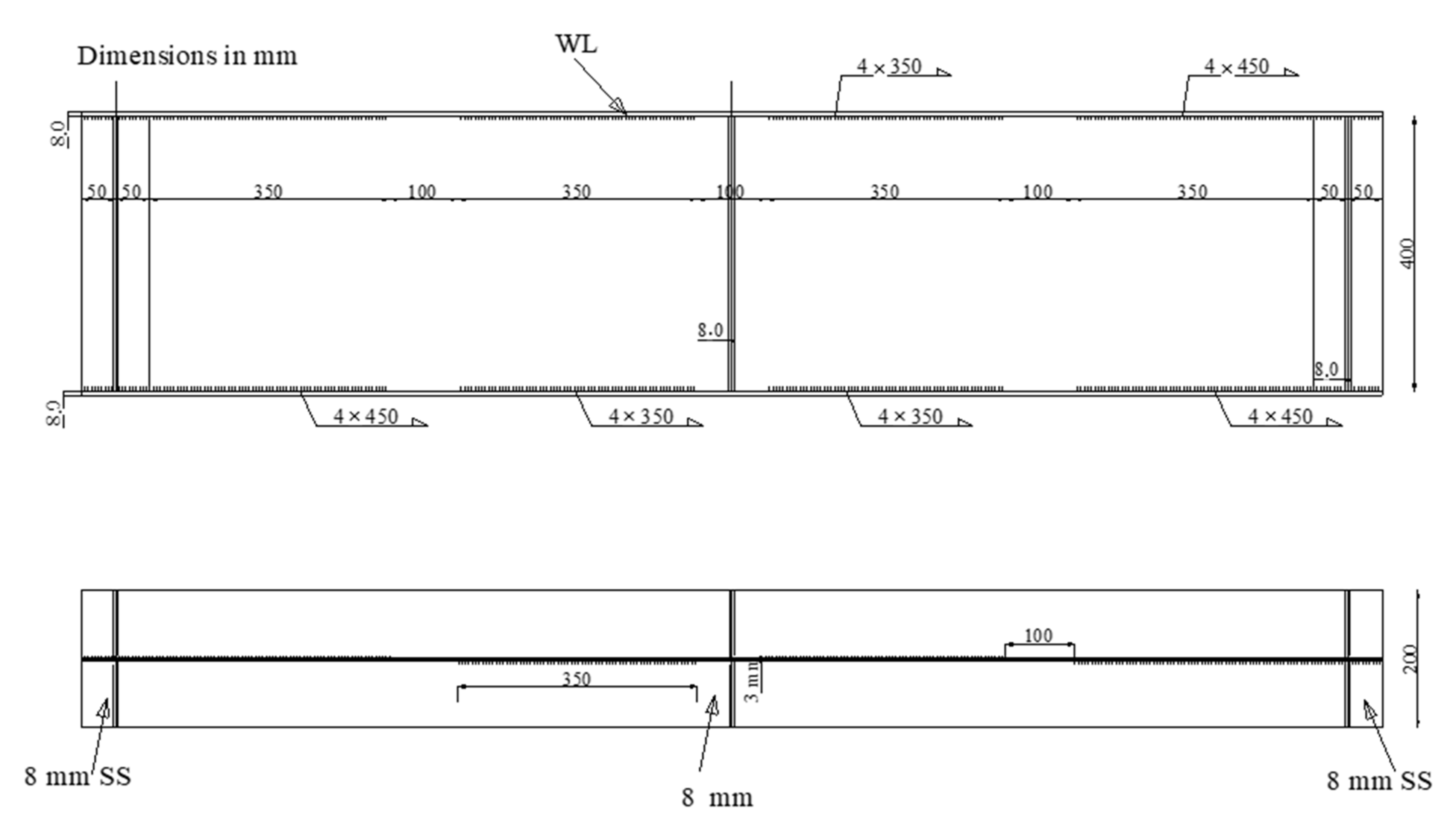
3.1. Fabrication and Details of Specimens
3.2. Properties of Materials
3.3. Test Setup and Instrumentation
4. Test Results and Discussion
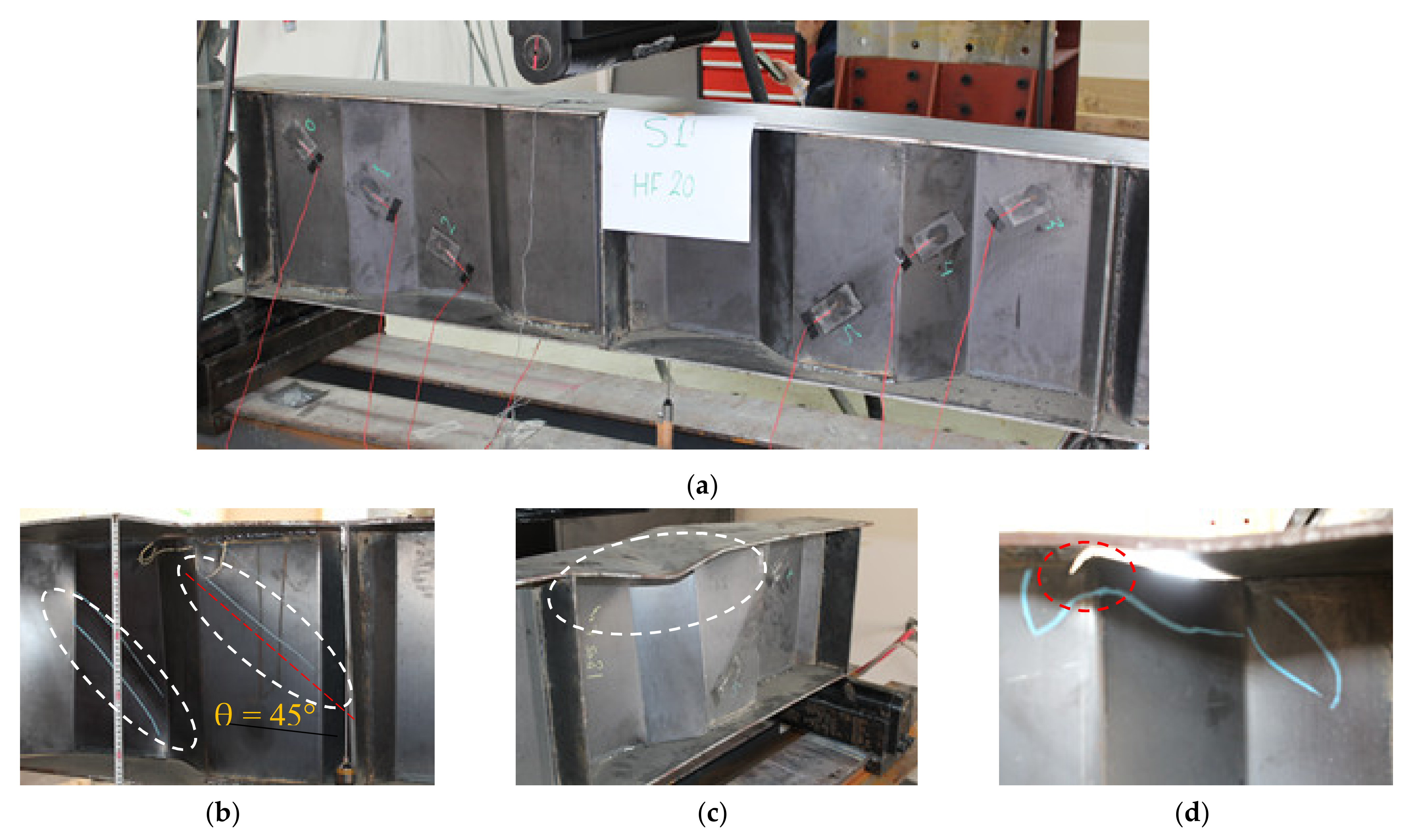
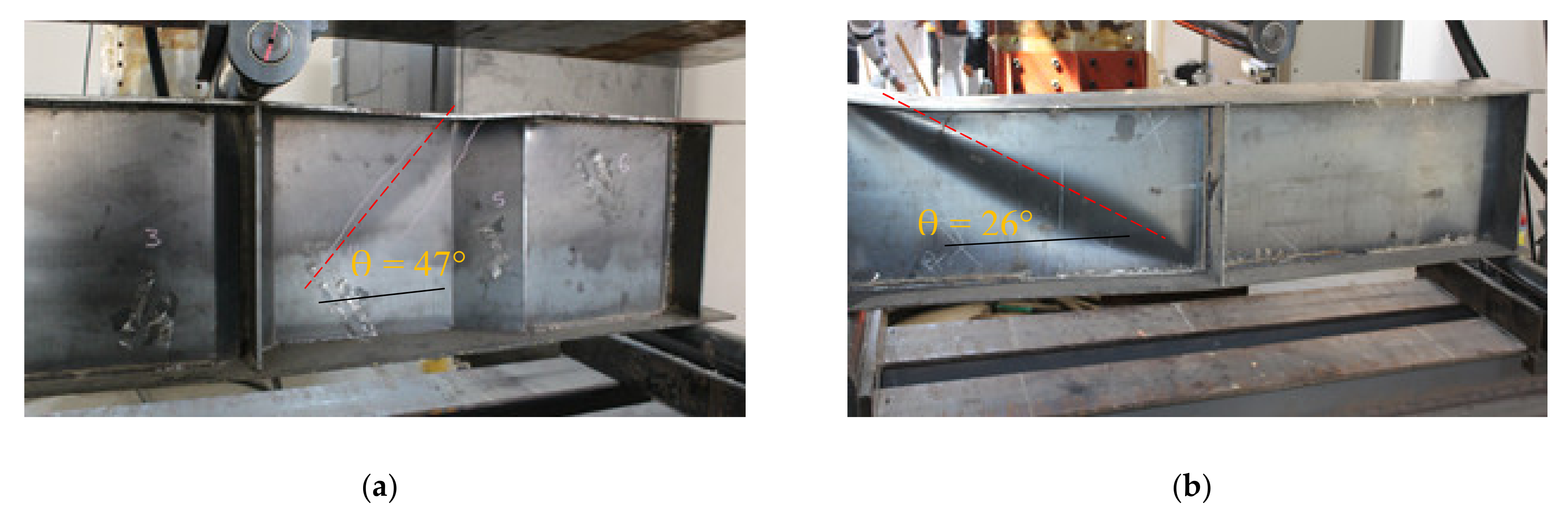
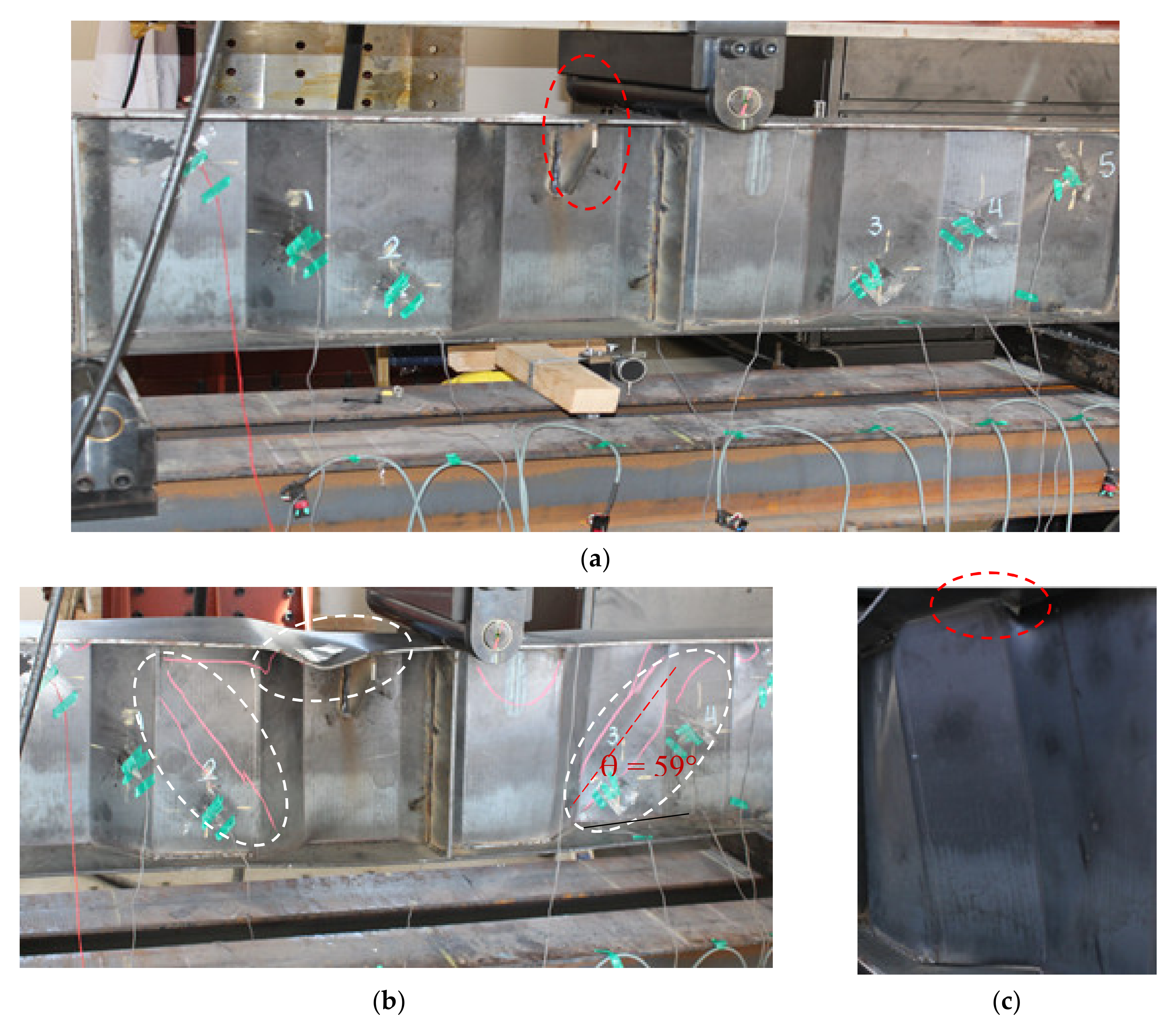
4.1. Loads Capacities and Failure Mechanisms of Tested Beams
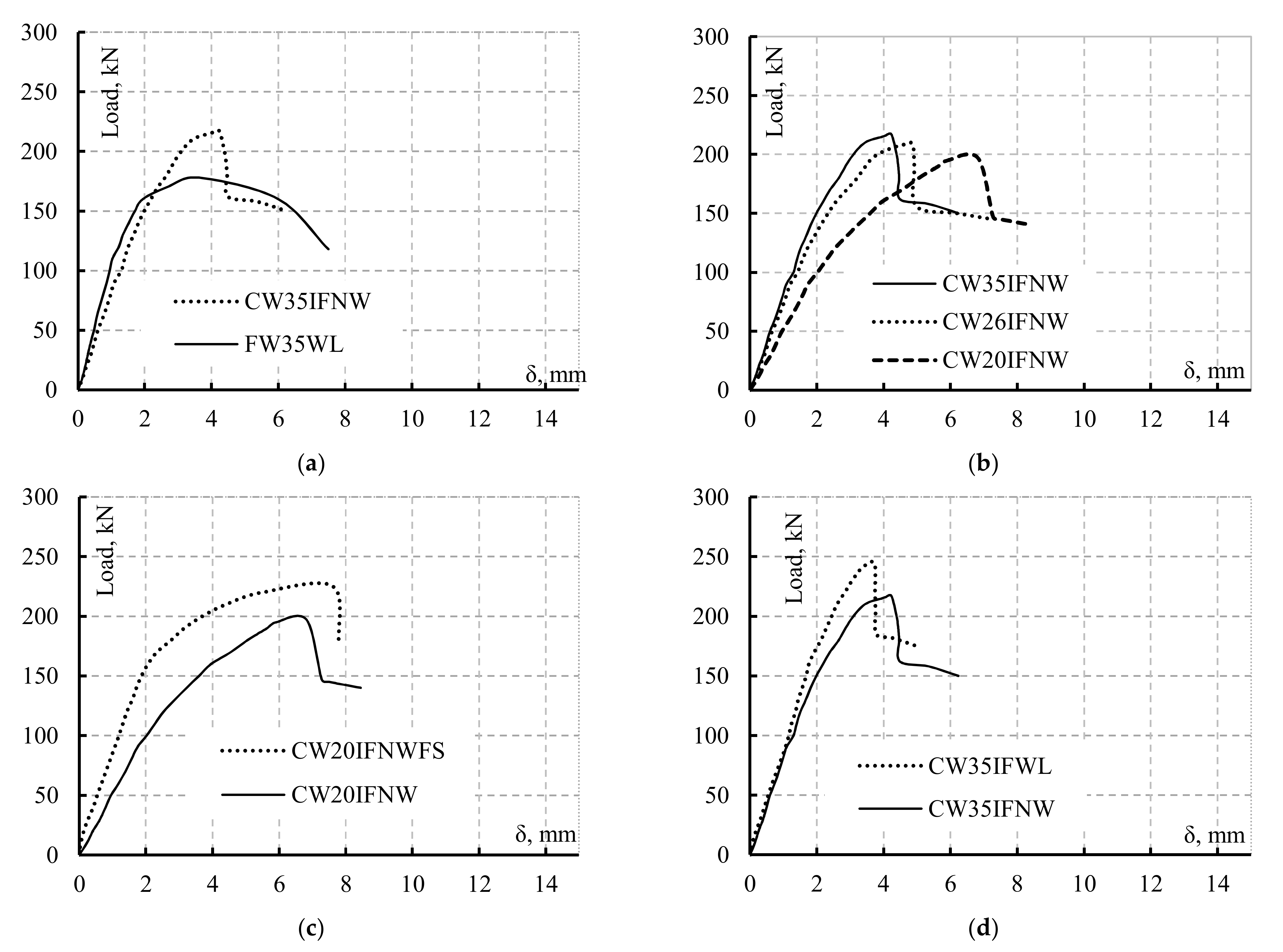
4.2. Load-Deflection Curves of Tested Beams
4.3. Efficiency of Transversal Stiffeners
4.4. Load-Strain Curves of Tested Beams
5. Theoretical Investigation of Flange Buckling
5.1. EN1993-1-5 Bending Resistance
5.2. Compression Flange Local Buckling Controlled by Flange Properties and Dimensions
6. Conclusions
Author Contributions
Funding
Institutional Review Board Statement
Informed Consent Statement
Data Availability Statement
Conflicts of Interest
References
- American Institute of Steel Construction AISC. Specification for Structural Steel Buildings; American Institute of Steel Construction: Chicago, IL, USA, 2016. [Google Scholar]
- Anami, K.; Sause, R. Fatigue of web-flange weld of corrugated web girders: 2. Analytical evaluation of fatigue strength of corrugated web-flange weld. Int. J. Fatigue 2005, 27, 383–393. [Google Scholar] [CrossRef]
- Abbas, H.H. Analysis and Design of Corrugated Web I-Girders for Bridges Using High Performance Steel. Ph.D. Thesis, Department of Civil and Environmental Engineering, Lehigh University, Bethlehem, PA, USA, 2003. [Google Scholar]
- Bergfelt, A.; Leiva-Aravena, L. Shear Buckling of Trapezoidally Corrugated Girder Webs; Division of steel and Timber Structures, Chalmers University of Technology: Gothenburg, Sweden, 1984; p. 84. [Google Scholar]
- Luo, R.; Edlund, B. Shear capacity of plate girders with trapezoidally corrugated webs. Thin-Walled Struct. 1996, 26, 19–44. [Google Scholar] [CrossRef]
- Shimada, S. Shearing strength of steel plate girders with folded web plate (Ripple web girders). Trans. Jpn. Soc. Civ. Eng. 1965, 1–10. [Google Scholar] [CrossRef] [Green Version]
- Elgaaly, M.; Hamilton, R.W.; Seshadri, A. Shear strength of beams with corrugated webs. J. Struct. Eng. 1996, 122, 390–398. [Google Scholar] [CrossRef]
- Sause, R.; Braxtan, T.N. Shear strength of trapezoidal corrugated steel webs. J. Constr. Steel Res. 2011, 67, 223–236. [Google Scholar] [CrossRef]
- Nie, J.G.; Zhu, L.; Tao, M.X.; Tang, L. Shear strength of trapezoidal corrugated steel webs. J. Constr. Steel Res. 2013, 85, 105–115. [Google Scholar] [CrossRef]
- Leblouba, M.; Junaid, M.T.; Barakat, S.; Altoubat, S.; Maalej, M. Shear buckling and stress distribution in trapezoidal web corrugated steel beams. Thin-Walled Struct. 2017, 113, 13–26. [Google Scholar] [CrossRef]
- Leblouba, M.; Barakat, S.; Altoubat, S.; Junaid, T.M.; Maalej, M. Normalized shear strength of trapezoidal corrugated steel webs. J. Constr. Steel Res. 2017, 136, 75–90. [Google Scholar] [CrossRef]
- Papangelis, J.; Trahair, N.; Hancock, G. Direct strength method for shear capacity of beams with corrugated webs. J. Constr. Steel Res. 2017, 137, 152–160. [Google Scholar] [CrossRef]
- Hassanein, M.F.; Elkawas, A.A.; El Hadidy, A.M.; Elchalakani, M. Shear analysis and design of high-strength steel corrugated web girders for bridge design. Eng. Struct. 2017, 146, 18–33. [Google Scholar] [CrossRef]
- Aggarwal, K.; Wu, S.; Papangelis, J. Finite element analysis of local shear buckling in corrugated web beams. Eng. Struct. 2018, 162, 37–50. [Google Scholar] [CrossRef]
- Leblouba, M.; Barakat, S.; Maalej, M.; Al-Toubat, S.; Karzad, A.S. Normalized shear strength of trapezoidal corrugated steel webs: Improved modeling and uncertainty propagation. Thin-Walled Struct. 2019, 137, 67–80. [Google Scholar] [CrossRef]
- Wang, S.; He, J.; Liu, Y. Shear behavior of steel I-girder with stiffened corrugated web, Part I: Experimental study. Thin-Walled Struct. 2019, 140, 248–262. [Google Scholar] [CrossRef]
- He, J.; Wang, S.; Liu, Y.; Wang, D.; Xin, H. Shear behavior of steel I-girder with stiffened corrugated web, Part II: Numerical study. Thin-Walled Struct. 2020, 147. [Google Scholar] [CrossRef]
- Abbas, H.H.; Sause, R.; Driver, R.G. Behavior of corrugated web I-girders under in-plane loads. J. Eng. Mech. 2006, 132, 806–814. [Google Scholar] [CrossRef]
- Abbas, H.H.; Sause, R.; Driver, R.G. Analysis of flange transverse bending of corrugated web I-girders under in-plane loads. J. Struct. Eng. 2007, 133, 347–355. [Google Scholar] [CrossRef]
- Abbas, H.H.; Sause, R.; Driver, R.G. Simplified analysis of flange transverse bending of corrugated web I-girders under in-plane moment and shear. Eng. Struct. 2007, 29, 2816–2824. [Google Scholar] [CrossRef]
- Easley, J.T.; McFarland, D.E. Buckling of light-gage corrugated metal shear diaphragms. J. Struct. Div. 1969, 95, 1497–1516. [Google Scholar] [CrossRef]
- Elamary, A.S.; Saddek, A.B.; Alwetaishi, M. Effect of corrugated web on flexural capacity of steel beams. Int. J. Appl. Eng. Res. 2017, 12, 470–481. [Google Scholar]
- Elgaaly, M.; Seshadri, A.; Hamilton, R.W. Bending strength of steel beams with corrugated webs. J. Struct. Eng. 1997, 123, 772–782. [Google Scholar] [CrossRef]
- Elgaaly, M.; Seshadri, A. Girders with corrugated webs under partial compressive edge loading. J. Struct. Eng. 1997, 123, 783–791. [Google Scholar] [CrossRef]
- Lindner, J. Granzschubtragfahigkeit von I-Tragern mit trapezforming profilierten Stegen. Stahlbau 1988, 57, 377–380. [Google Scholar]
- Elamary, A.; Ahmed, M.M.; Mohmoud, A.M. Flexural behaviour and capacity of reinforced concrete–steel composite beams with corrugated web and top steel flange. Eng. Struct. 2017, 135, 136–148. [Google Scholar] [CrossRef]
- Śledziewski, K.; Górecki, M. Finite Element Analysis of the Stability of a Sinusoidal Web in Steel and Composite Steel-Concrete Girders. Materials 2020, 13, 1041. [Google Scholar] [CrossRef] [PubMed] [Green Version]
- Huang, L.; Hikosaka, H.; Komine, K. Simulation of accordion effect in corrugated steel web with concrete flanges. Comput. Struct. 2004, 82, 2061–2069. [Google Scholar] [CrossRef]
- Lindner, J. Zur bemessung von trapezstegträgern. Der Stahlbau 1992, 61, 311–318. [Google Scholar]
- Aschinger, R.; Lindner, J. Zu besonderheiten bei Trapezstegträgern. Der Stahlbau 1997, 3, 136–142. [Google Scholar]
- Pasternak, H.; Kubieniec, G. Plate girders with corrugated webs. J. Civ. Eng. Manag. 2010, 16, 166–171. [Google Scholar] [CrossRef] [Green Version]
- Sherman, D.R.; Fisher, J.M. Beam with Corrugated Webs. In Proceedings of the First International Specialty Conference on Cold-Formed Steel Structures, Rolla, MO, USA, 20 August 1971. [Google Scholar]
- Kollár, D.; Kövesdi, B. Welding simulation of corrugated web girders—Part 2: Effect of manufacturing on shear buckling resistance. Thin-Walled Struct. 2019, 141, 477–488. [Google Scholar] [CrossRef]
- Kollár, D.; Kövesdi, B. Welding simulation of corrugated web girders—Part 1: Effect of manufacturing on residual stresses and imperfections. Thin-Walled Struct. 2020, 146, 106107. [Google Scholar] [CrossRef]
- The European Union. EN 1993-1-5, Eurocode 3—Design of Steel Structures—Part 1–5: Plated Structural Elements; JRC Scientific and Technical Reports; European Committee for Standardization: Brussels, Belgium, 2006; pp. 1–53. [Google Scholar]
- Kövesdi, B.; Jáger, B.; Dunai, L. Stress distribution in the flanges of girders with corrugated webs. J. Constr. Steel Res. 2012, 79, 204–215. [Google Scholar] [CrossRef]
- Johnson, R.P.; Cafolla, J. Local flange buckling in plate girders with corrugated steel webs. Proc Inst. Civ. Eng. Struct. Build. 1997, 122, 148–156. [Google Scholar] [CrossRef]


| Specimen ID | Web | Flange Dimensions (mm) | Welding between Web and Flanges | Test Variables | ||||
|---|---|---|---|---|---|---|---|---|
| Shape | Dimensions (mm) | |||||||
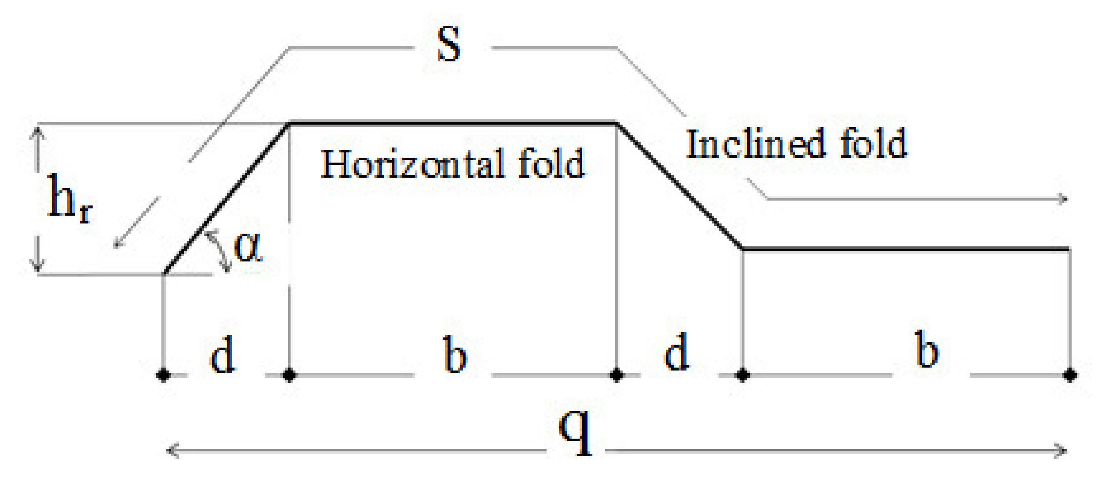
| b | d | hr | t | |||||
| CW20IFNW | Trapezoidal Corrugated | 200 | 100 | 100 | 3 | 200 × 8 | HF only | HF * length |
| CW26IFNW | 260 | HF * length | ||||||
| CW35IFNW | 350 | HF * length | ||||||
| CW20IFNWFS | 200 | FS | ||||||
| CW35IFWL | 350 | Both HF * and IF ** | WL | |||||
| FW35WL | Flat | -- | -- | -- | 3 | intermittent welding line length 35 cm | ||
| Coupon Type | Average fy (N/mm2) | Average fu (N/mm2) | Average E (Gpa) | Maximum Strain |
|---|---|---|---|---|
| Flange | 225 | 320 | 200 | 0.028 |
| Web | 420 | 530 | 201 | 0.065 |
| Specimen | Failure Load (kN) | Failure Mode Mechanisms | Deflection at pu (mm) | ||||
|---|---|---|---|---|---|---|---|
| Web | Flange | Additional | |||||
| Mode | Angle | δout, mm | δ, mm | ||||
| CW20IFNW | 197 | LB * | 45° | LB | Web/tear out | 35 | 6.3 |
| CW26IFNW | 208 | LB | 46° | LB | Web/tear out | 30 | 4.9 |
| CW35IFNW | 217 | LB | 47° | LB | Web/tear out | 32 | 4.2 |
| CW20IFNWFS | 225 | LB | 59° | LB | Web/tear out | 25 | 7.8 |
| CW35IFWL | 245 | -- | -- | LB | -- | 23 | 3.8 |
| FW35WL | 178 | GB ** | 26° | -- | -- | 2 | 7.3 |
Publisher’s Note: MDPI stays neutral with regard to jurisdictional claims in published maps and institutional affiliations. |
© 2021 by the authors. Licensee MDPI, Basel, Switzerland. This article is an open access article distributed under the terms and conditions of the Creative Commons Attribution (CC BY) license (http://creativecommons.org/licenses/by/4.0/).
Share and Cite
Elamary, A.S.; Alharthi, Y.; Abdalla, O.; Alqurashi, M.; Sharaky, I.A. Failure Mechanism of Hybrid Steel Beams with Trapezoidal Corrugated-Web Non-Welded Inclined Folds. Materials 2021, 14, 1424. https://doi.org/10.3390/ma14061424
Elamary AS, Alharthi Y, Abdalla O, Alqurashi M, Sharaky IA. Failure Mechanism of Hybrid Steel Beams with Trapezoidal Corrugated-Web Non-Welded Inclined Folds. Materials. 2021; 14(6):1424. https://doi.org/10.3390/ma14061424
Chicago/Turabian StyleElamary, Ahmed S., Yasir Alharthi, Osama Abdalla, Muwaffaq Alqurashi, and Ibrahim A. Sharaky. 2021. "Failure Mechanism of Hybrid Steel Beams with Trapezoidal Corrugated-Web Non-Welded Inclined Folds" Materials 14, no. 6: 1424. https://doi.org/10.3390/ma14061424