
Investigating the Efficacy of Adhesive Tape for Drilling Carbon Fibre Reinforced Polymers

 ,
, 
 ,
,  ,
,  ,
,  ,
,  ,
,  and
and 
Abstract
:1. Introduction
2. Materials and Methods
3. Results and Discussion
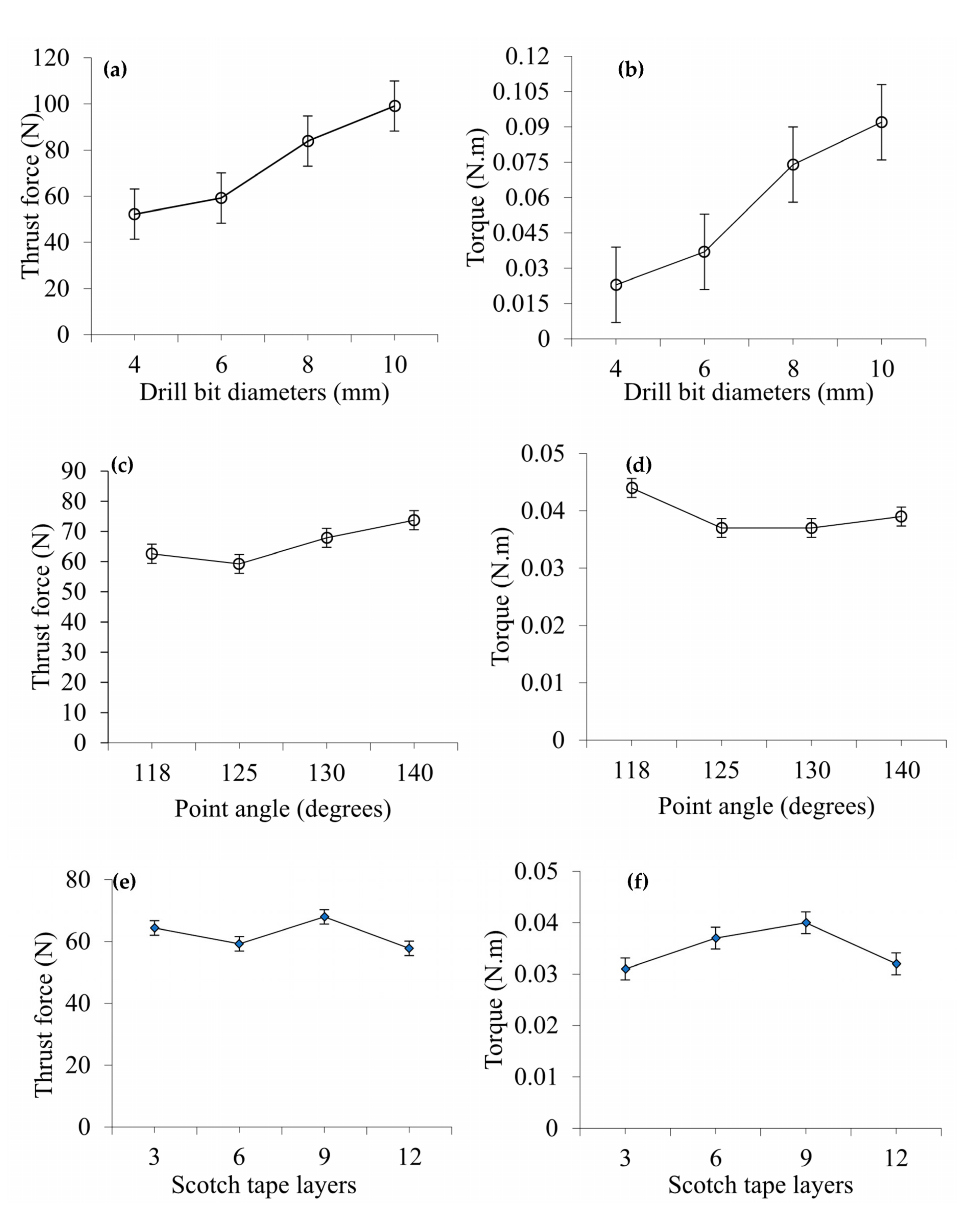
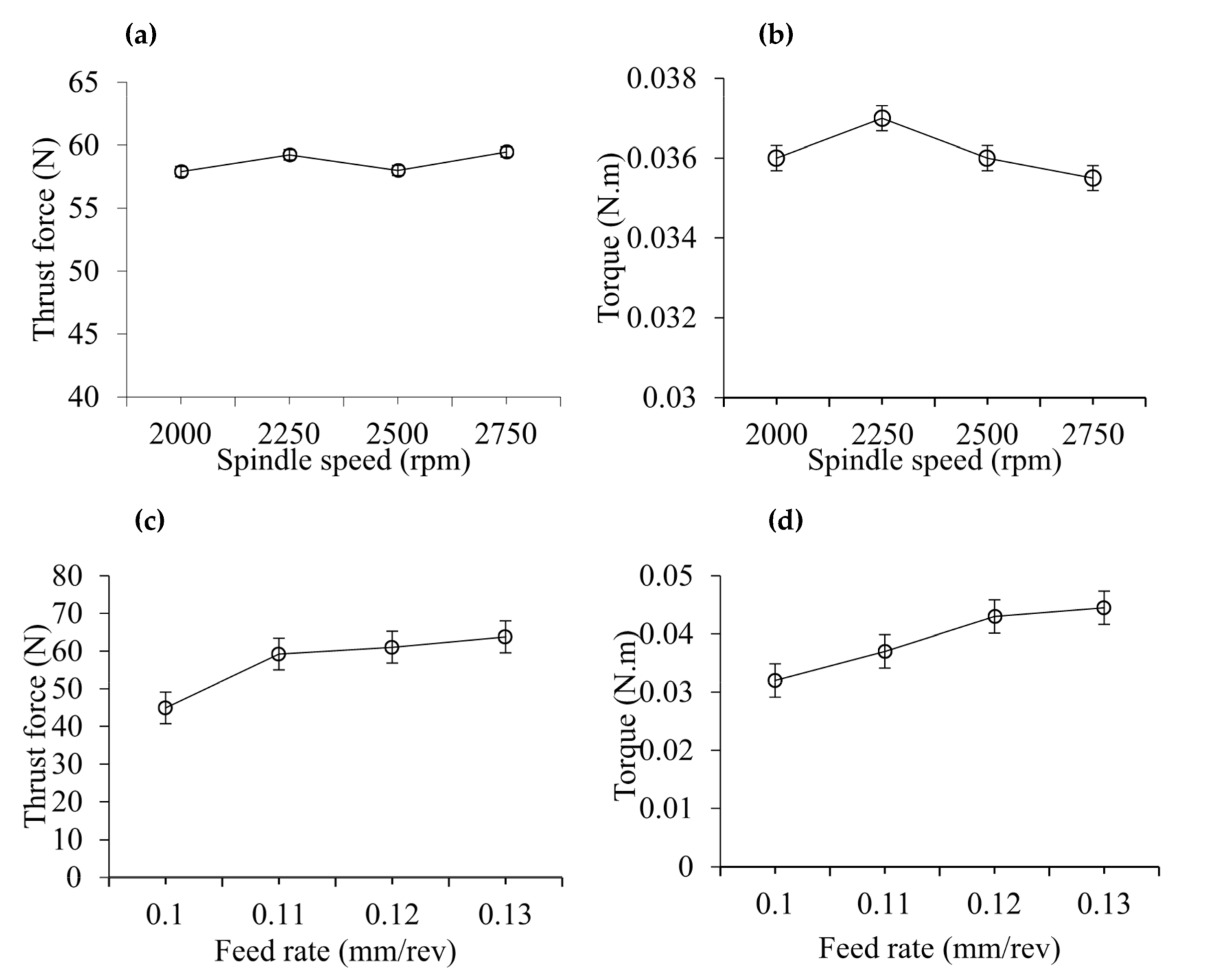
3.1. Thrust Force and Torque
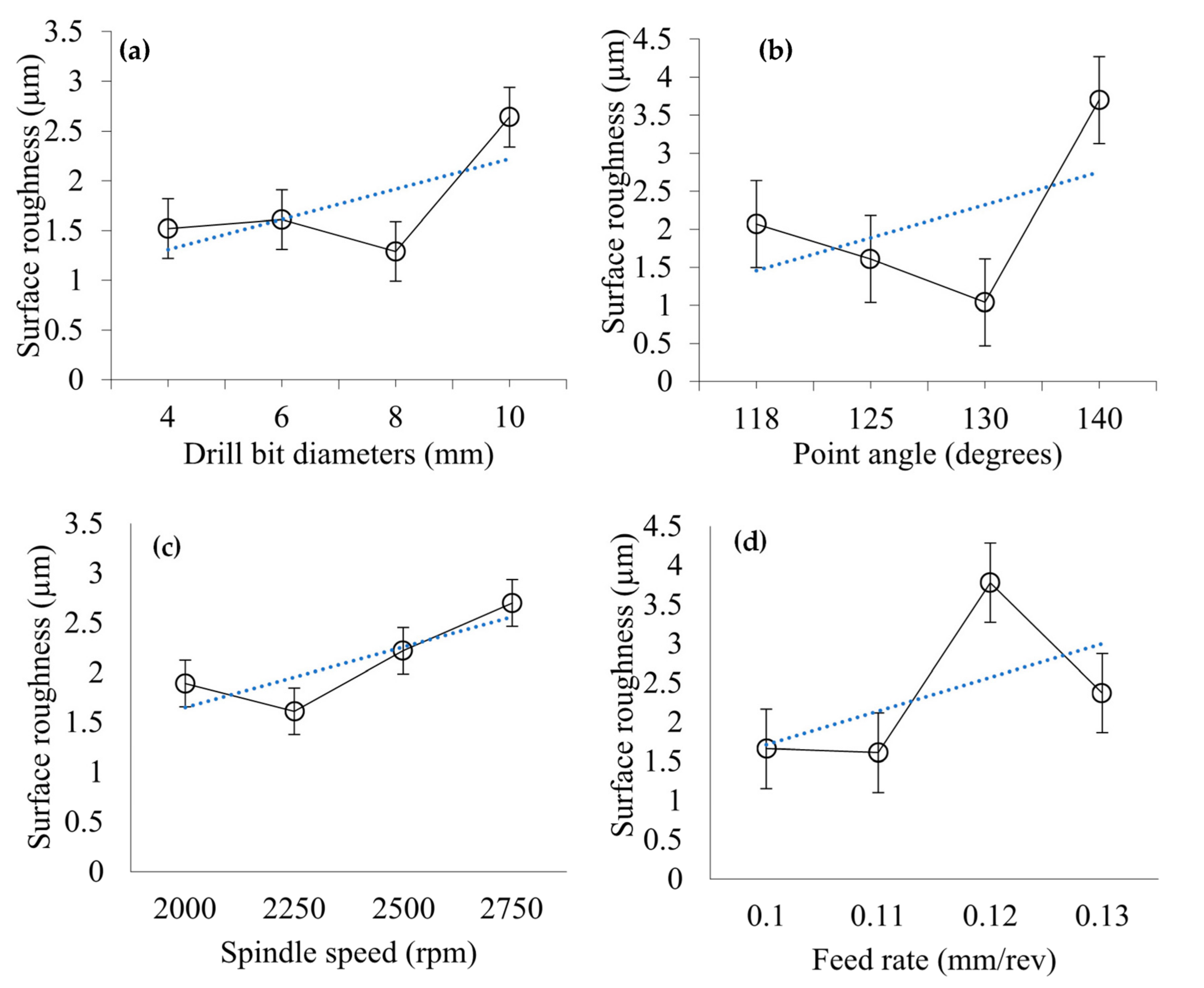
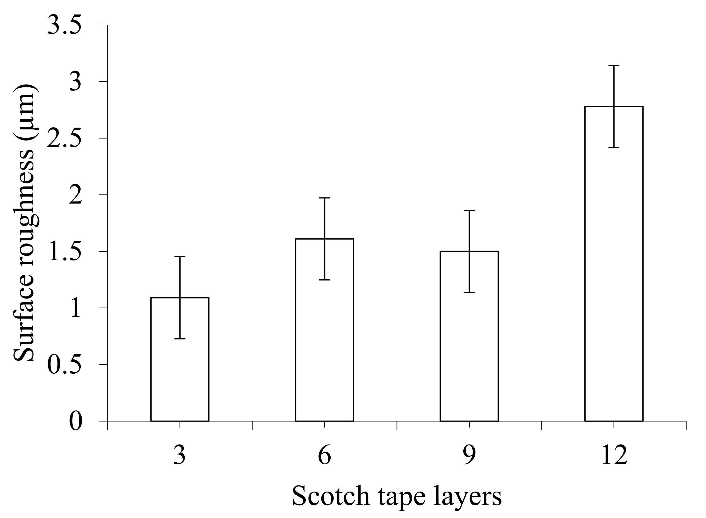
3.2. Surface Roughness
3.3. Circularity
3.4. Diameter Error
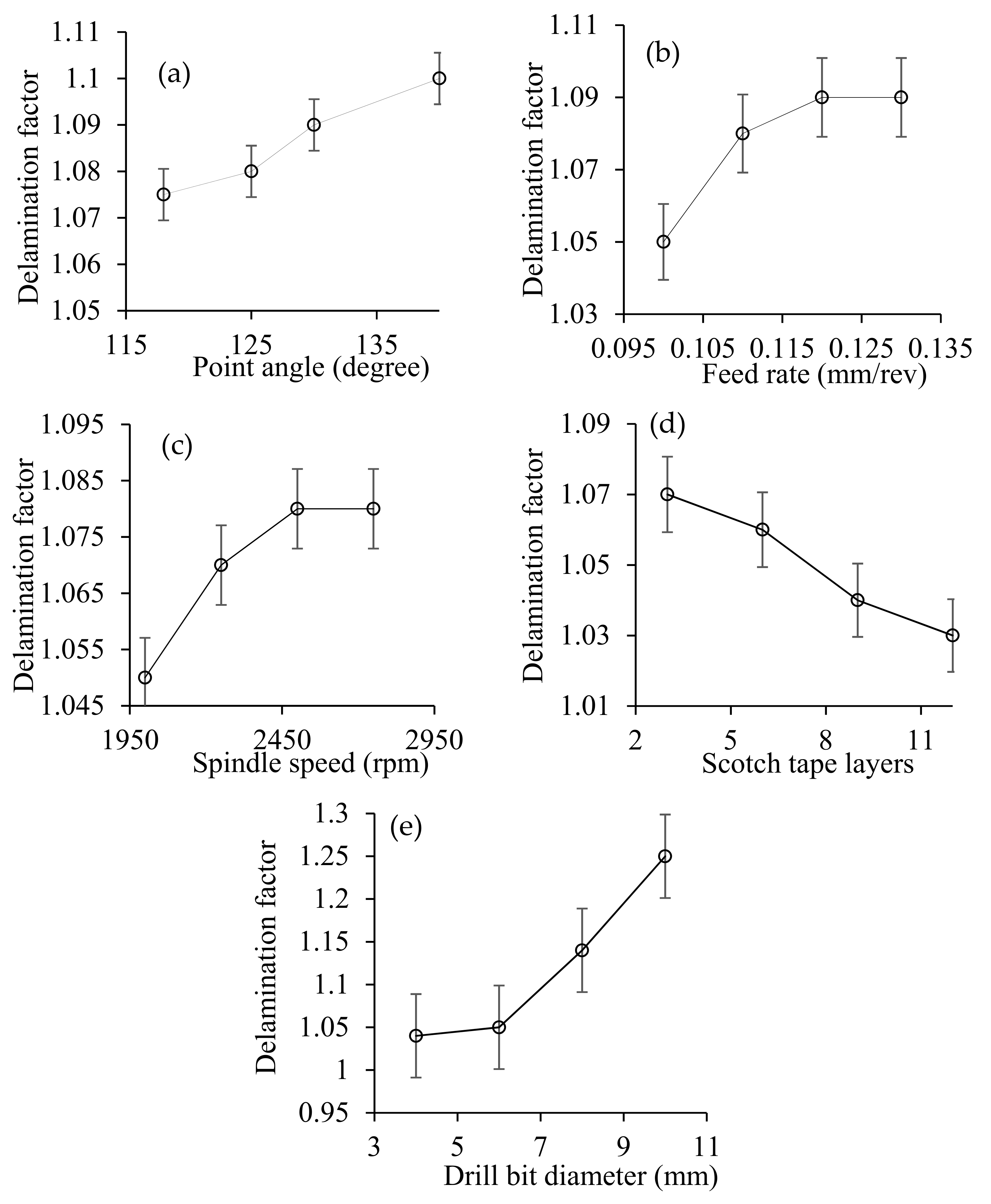
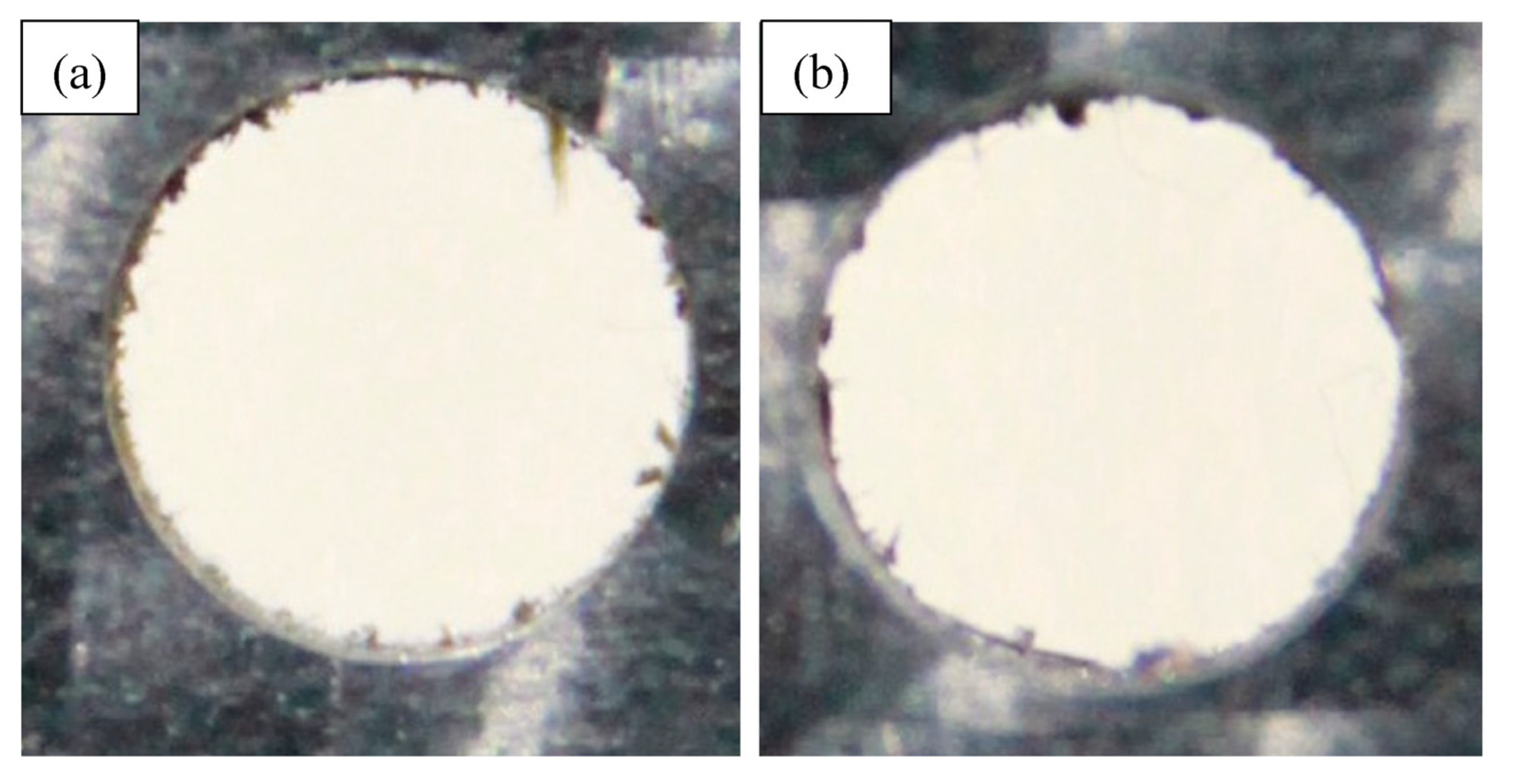
3.5. Delamination
4. Conclusions
Author Contributions
Funding
Institutional Review Board Statement
Informed Consent Statement
Data Availability Statement
Conflicts of Interest
References
- Pramanik, A.; Basak, A.; Dong, Y.; Sarker, P.; Uddin, M.; Littlefair, G.; Dixit, A.; Chattopadhyaya, S. Joining of carbon fibre reinforced polymer (CFRP) composites and aluminium alloys—A review. Compos. Part A Appl. Sci. Manuf. 2017, 101, 1–29. [Google Scholar] [CrossRef] [Green Version]
- Ismail, S.O.; Dhakal, H.N.; Popov, I.; Beaugrand, J. Comprehensive study on machinability of sustainable and conventional fibre reinforced polymer composites. Eng. Sci. Technol. Int. J. 2016, 19, 2043–2052. [Google Scholar] [CrossRef]
- Geier, N.; Szalay, T.; Takács, M. Analysis of thrust force and characteristics of uncut fibres at non-conventional oriented drilling of unidirectional carbon fibre-reinforced plastic (UD-CFRP) composite laminates. Int. J. Adv. Manuf. Technol. 2018, 100, 3139–3154. [Google Scholar] [CrossRef]
- Geier, N.; Davim, J.P.; Szalay, T. Advanced cutting tools and technologies for drilling carbon fibre reinforced polymer (CFRP) composites: A review. Compos. Part A Appl. Sci. Manuf. 2019, 125, 105552. [Google Scholar] [CrossRef]
- Melentiev, R.; Priarone, P.C.; Robiglio, M.; Settineri, L. Effects of Tool Geometry and Process Parameters on Delamination in CFRP Drilling: An Overview. Procedia CIRP 2016, 45, 31–34. [Google Scholar] [CrossRef] [Green Version]
- Pramanik, A.; Littlefair, G. Developments in Machining of Stacked Materials Made of CFRP and Titanium/Aluminum Alloys. Mach. Sci. Technol. 2014, 18, 485–508. [Google Scholar] [CrossRef]
- Pramanik, A.; Basak, A.K.; Islam, M.N.; Dong, Y.; Debnath, S.; Vora, J.J. Optimization of Accuracy and Surface Finish of Drilled Holes in 350 Mild Steel. In Cooperating Robots for Flexible Manufacturing; Springer: Berlin/Heidelberg, Germany, 2019; pp. 65–90. [Google Scholar]
- Pramanik, A.; Basak, A.K.; Uddin, M.S.; Shankar, S.; Debnath, S.; Islam, M.N. Burr formation during drilling of mild steel at different machining conditions. Mater. Manuf. Process. 2019, 34, 726–735. [Google Scholar] [CrossRef]
- Davim, J.; Reis, P.; António, C. Experimental study of drilling glass fiber reinforced plastics (GFRP) manufactured by hand lay-up. Compos. Sci. Technol. 2004, 64, 289–297. [Google Scholar] [CrossRef]
- Davim, J.P.; Reis, P.; António, C.C. Drilling fiber reinforced plastics (FRPs) manufactured by hand lay-up: Influence of matrix (Viapal VUP 9731 and ATLAC 382-05). J. Mater. Process. Technol. 2004, 155–156, 1828–1833. [Google Scholar] [CrossRef]
- Tsao, C.C. Thrust force and delamination of core-saw drill during drilling of carbon fiber reinforced plastics (CFRP). Int. J. Adv. Manuf. Technol. 2007, 37, 23–28. [Google Scholar] [CrossRef]
- Tsao, C.; Chiu, Y. Evaluation of drilling parameters on thrust force in drilling carbon fiber reinforced plastic (CFRP) composite laminates using compound core-special drills. Int. J. Mach. Tools Manuf. 2011, 51, 740–744. [Google Scholar] [CrossRef]
- Khashaba, U. Drilling of polymer matrix composites: A review. J. Compos. Mater. 2012, 47, 1817–1832. [Google Scholar] [CrossRef]
- Kumar, D.; Singh, K. An approach towards damage free machining of CFRP and GFRP composite material: A review. Adv. Compos. Materials 2014, 24, 49–63. [Google Scholar] [CrossRef]
- Khanna, N.; Pusavec, F.; Agrawal, C.; Krolczyk, G.M. Measurement and evaluation of hole attributes for drilling CFRP composites using an indigenously developed cryogenic machining facility. Measurement 2020, 154, 107504. [Google Scholar] [CrossRef]
- Geng, D.; Lu, Z.; Yao, G.; Liu, J.; Li, Z.; Zhang, D. Cutting temperature and resulting influence on machining performance in rotary ultrasonic elliptical machining of thick CFRP. Int. J. Mach. Tools Manuf. 2017, 123, 160–170. [Google Scholar] [CrossRef]
- Feito, N.; Díaz-Álvarez, J.; Díaz-Álvarez, A.; Cantero, J.L.; Miguélez, M.H. Experimental Analysis of the Influence of Drill Point Angle and Wear on the Drilling of Woven CFRPs. Materials 2014, 7, 4258–4271. [Google Scholar] [CrossRef] [PubMed] [Green Version]
- Feito, N.; López-Puente, J.; Santiuste, C.; Miguélez, M. Numerical prediction of delamination in CFRP drilling. Compos. Struct. 2014, 108, 677–683. [Google Scholar] [CrossRef] [Green Version]
- Phadnis, V.A.; Makhdum, F.; Roy, A.; Silberschmidt, V.V. Drilling in carbon/epoxy composites: Experimental investigations and finite element implementation. Compos. Part A Appl. Sci. Manuf. 2013, 47, 41–51. [Google Scholar] [CrossRef] [Green Version]
- Merino-Pérez, J.L.; Royer, R.; Merson, E.; Lockwood, A.; Ayvar-Soberanis, S.; Marshall, M.B. Influence of workpiece constituents and cutting speed on the cutting forces developed in the conventional drilling of CFRP composites. Compos. Struct. 2016, 140, 621–629. [Google Scholar] [CrossRef] [Green Version]
- Ahmad, N.; Khan, S.A.; Raza, S.F. Influence of hole diameter, workpiece thickness, and tool surface condition on machinability of CFRP composites in orbital drilling: A case of workpiece rotation. Int. J. Adv. Manuf. Technol. 2019, 103, 2007–2015. [Google Scholar] [CrossRef]
- Zitoune, R.; Krishnaraj, V.; Almabouacif, B.S.; Collombet, F.; Sima, M.; Jolin, A. Influence of machining parameters and new nano-coated tool on drilling performance of CFRP/Aluminium sandwich. Compos. Part B Eng. 2012, 43, 1480–1488. [Google Scholar] [CrossRef]
- Zitoune, R.; Krishnaraj, V.; Collombet, F. Study of drilling of composite material and aluminium stack. Compos. Struct. 2010, 92, 1246–1255. [Google Scholar] [CrossRef]
- Geier, N.; Pereszlai, C. Analysis of Characteristics of Surface Roughness of Machined CFRP Composites. Period. Polytech. Mech. Eng. 2019, 64, 67–80. [Google Scholar] [CrossRef] [Green Version]
- Pereszlai, C.; Geier, N. Comparative analysis of wobble milling, helical milling and conventional drilling of CFRPs. Int. J. Adv. Manuf. Technol. 2020, 106, 3913–3930. [Google Scholar] [CrossRef] [Green Version]
- Nomani, J.; Pramanik, A.; Hilditch, T.; Littlefair, G. Machinability study of first generation duplex (2205), second generation duplex (2507) and austenite stainless steel during drilling process. Wear 2013, 304, 20–28. [Google Scholar] [CrossRef] [Green Version]


| Experiment No. | Diameter (mm) | Point Angle (Degrees) | Scotch Tape Layers (No.) | Speed (rpm) | Feed (mm/rev) |
|---|---|---|---|---|---|
| 1 | 4 | 125 | 6 | 2250 | 0.11 |
| 2 | 6 | 125 | 6 | 2250 | 0.11 |
| 3 | 8 | 125 | 6 | 2250 | 0.11 |
| 4 | 10 | 125 | 6 | 2250 | 0.11 |
| 5 | 6 | 118 | 6 | 2250 | 0.11 |
| 6 | 6 | 130 | 6 | 2250 | 0.11 |
| 7 | 6 | 140 | 6 | 2250 | 0.11 |
| 8 | 6 | 125 | 3 | 2250 | 0.11 |
| 9 | 6 | 125 | 9 | 2250 | 0.11 |
| 10 | 6 | 125 | 12 | 2250 | 0.11 |
| 11 | 6 | 125 | 6 | 2000 | 0.11 |
| 12 | 6 | 125 | 6 | 2500 | 0.11 |
| 13 | 6 | 125 | 6 | 2750 | 0.11 |
| 14 | 6 | 125 | 6 | 2250 | 0.10 |
| 15 | 6 | 125 | 6 | 2250 | 0.12 |
| 16 | 6 | 125 | 6 | 2250 | 0.13 |
Publisher’s Note: MDPI stays neutral with regard to jurisdictional claims in published maps and institutional affiliations. |
© 2021 by the authors. Licensee MDPI, Basel, Switzerland. This article is an open access article distributed under the terms and conditions of the Creative Commons Attribution (CC BY) license (http://creativecommons.org/licenses/by/4.0/).
Share and Cite
Prakash, C.; Pramanik, A.; Basak, A.K.; Dong, Y.; Debnath, S.; Shankar, S.; Singh, S.; Wu, L.Y.; Zheng, H.Y. Investigating the Efficacy of Adhesive Tape for Drilling Carbon Fibre Reinforced Polymers. Materials 2021, 14, 1699. https://doi.org/10.3390/ma14071699
Prakash C, Pramanik A, Basak AK, Dong Y, Debnath S, Shankar S, Singh S, Wu LY, Zheng HY. Investigating the Efficacy of Adhesive Tape for Drilling Carbon Fibre Reinforced Polymers. Materials. 2021; 14(7):1699. https://doi.org/10.3390/ma14071699
Chicago/Turabian StylePrakash, Chander, Alokesh Pramanik, Animesh K. Basak, Yu Dong, Sujan Debnath, Subramaniam Shankar, Sunpreet Singh, Linda Yongling Wu, and Hongyu Y. Zheng. 2021. "Investigating the Efficacy of Adhesive Tape for Drilling Carbon Fibre Reinforced Polymers" Materials 14, no. 7: 1699. https://doi.org/10.3390/ma14071699
APA StylePrakash, C., Pramanik, A., Basak, A. K., Dong, Y., Debnath, S., Shankar, S., Singh, S., Wu, L. Y., & Zheng, H. Y. (2021). Investigating the Efficacy of Adhesive Tape for Drilling Carbon Fibre Reinforced Polymers. Materials, 14(7), 1699. https://doi.org/10.3390/ma14071699