Post Fire Residual Strength of the Wall-Slab Using Siliceous Concrete
Abstract
:1. Introduction
2. Wall–Slab Connection Residual Performance Test
2.1. Material Test
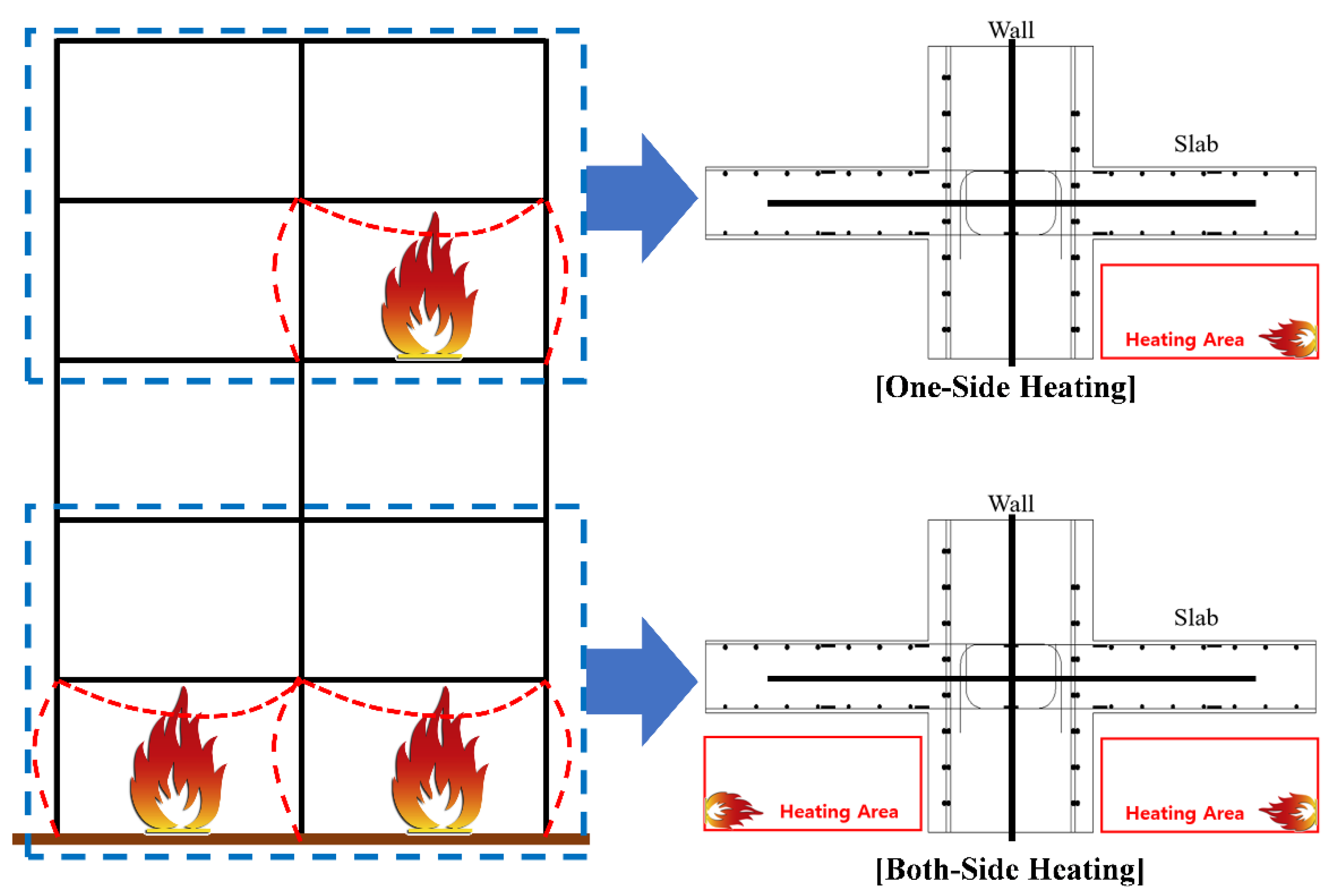
2.2. Wall-Slab Connection Specimen Fabrication Plan
- Live load and other loads (including only self-weight of test specimen);
- Axial restraint effect;
- Pressure if the furnace-related to the atmosphere around the specimen;
- Thermal properties, such as thermal expansion and heat flux.
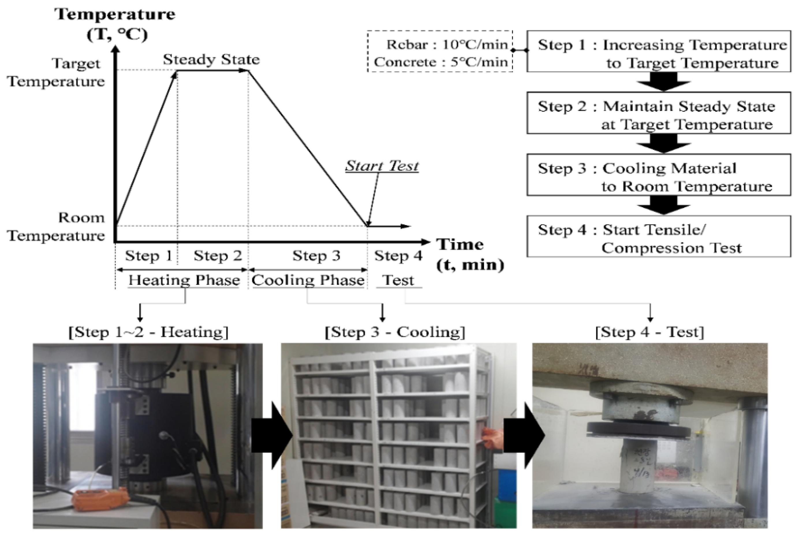
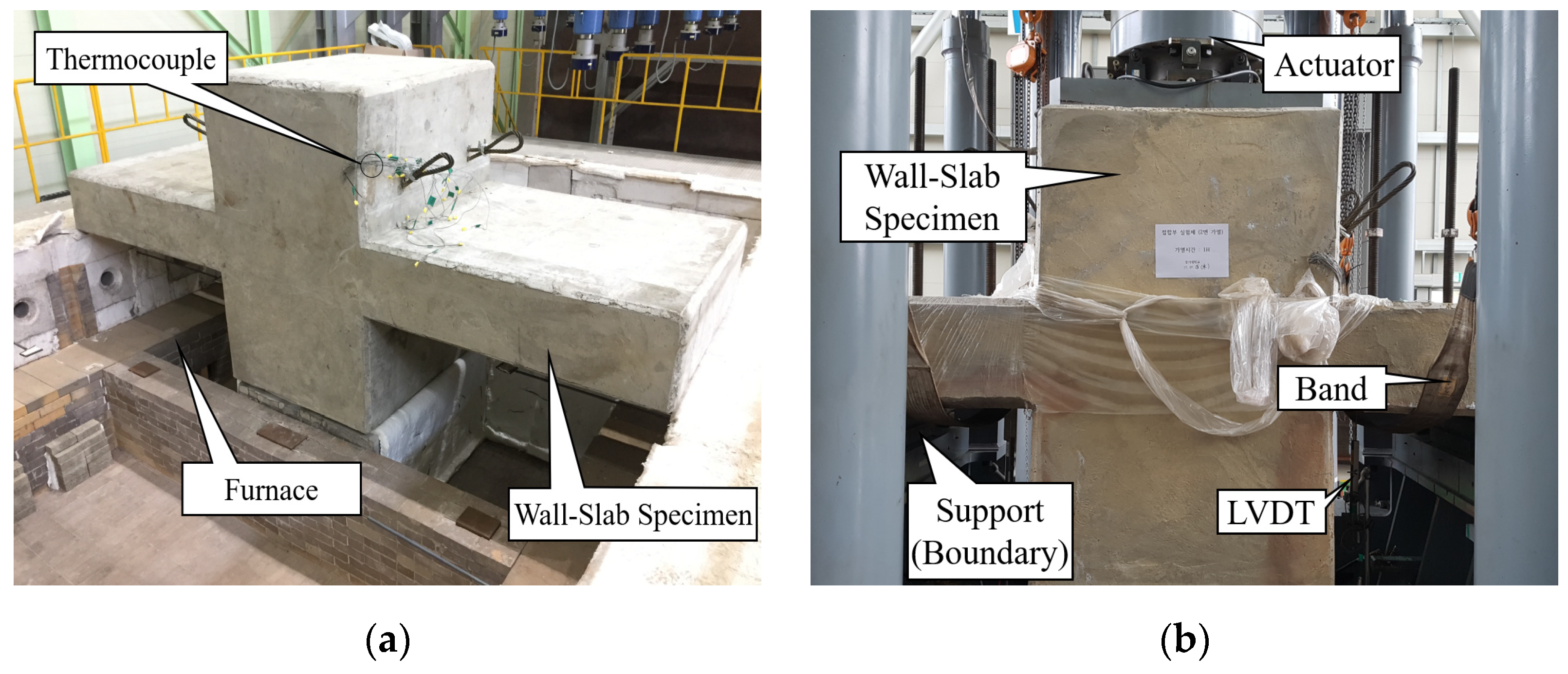
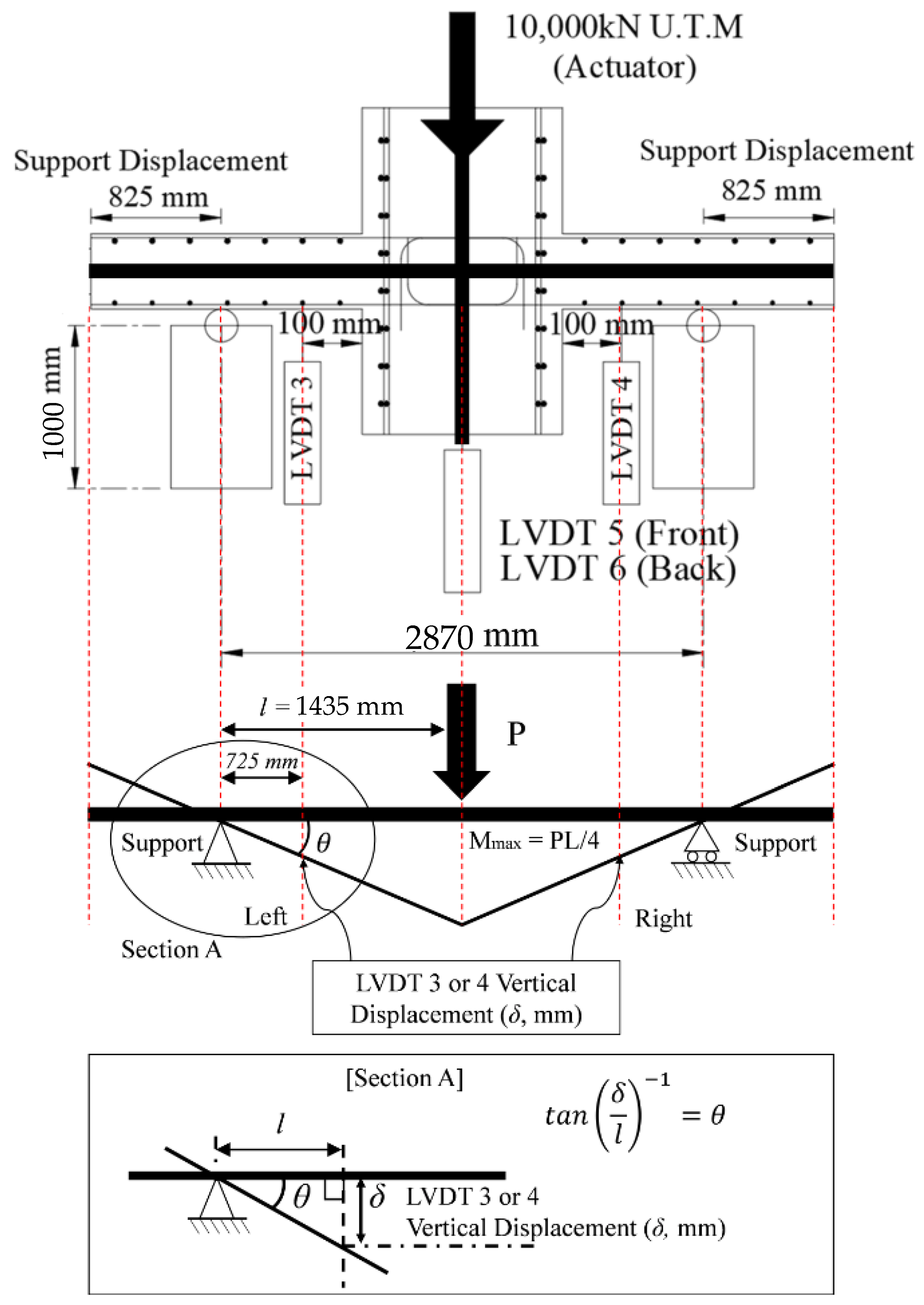
2.3. Test Method
3. Fire Test Results and Discussion
3.1. Temperature Distribution
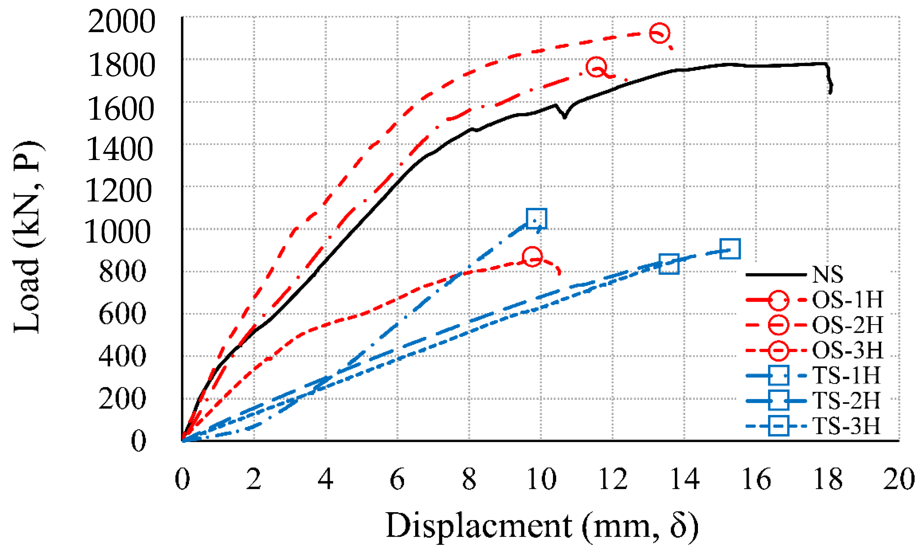
3.2. Load–Displacement Relationship
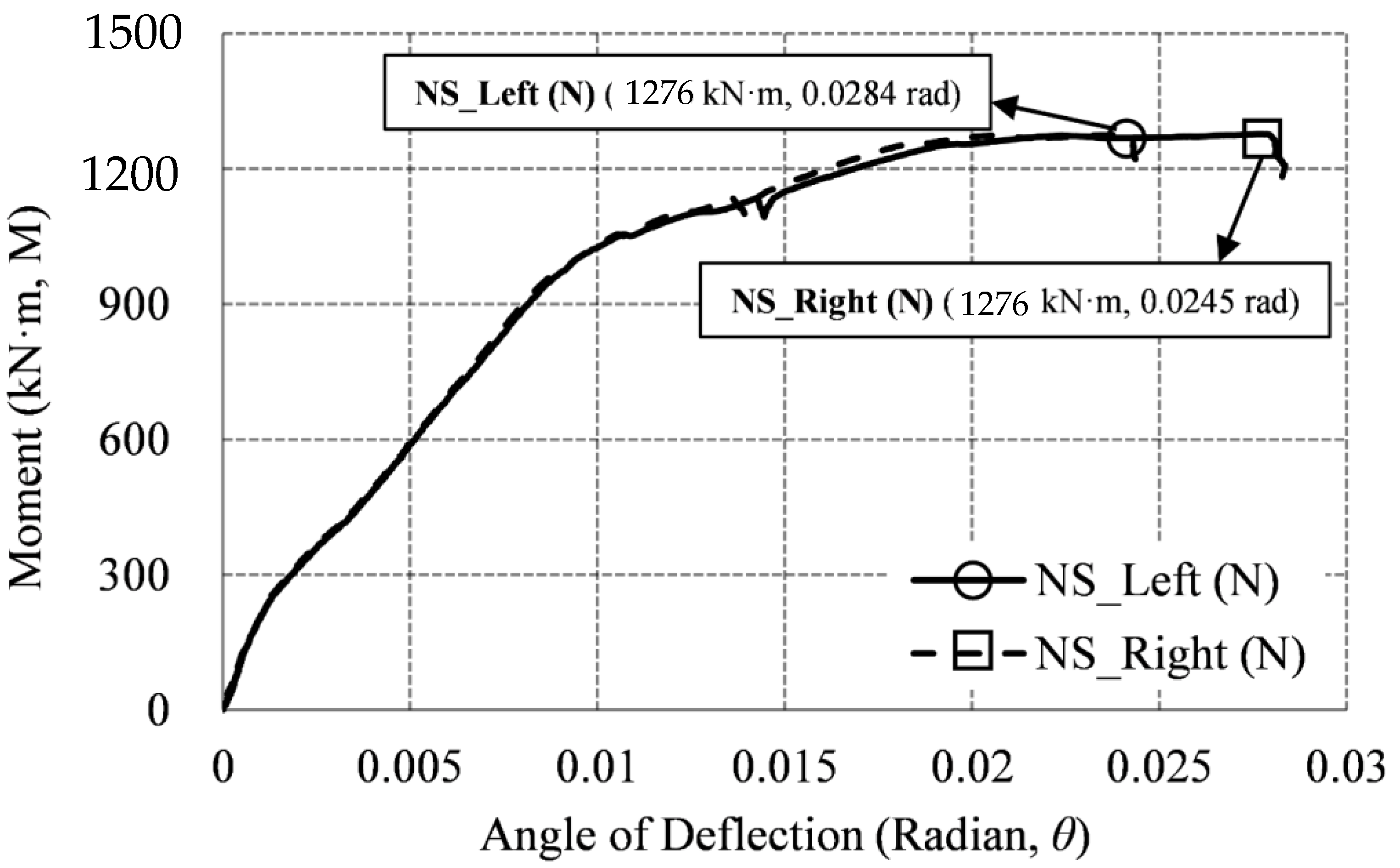
3.3. Moment–Deflection Angle Relationship
3.3.1. Non–Heating Specimen (NS)
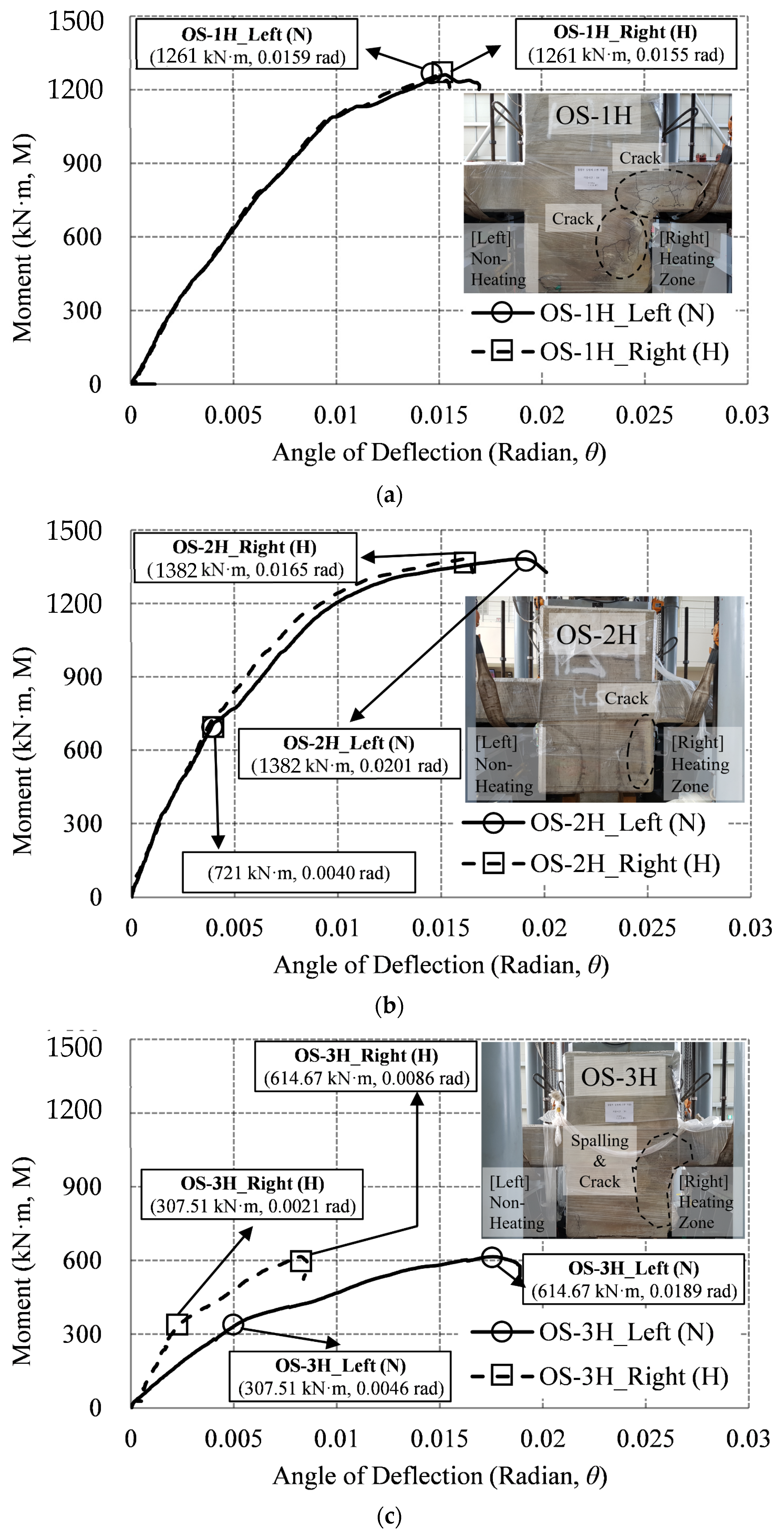
3.3.2. One–Sided Heating Specimen (OS)
3.3.3. Two–Sided Heating Specimen (TS)
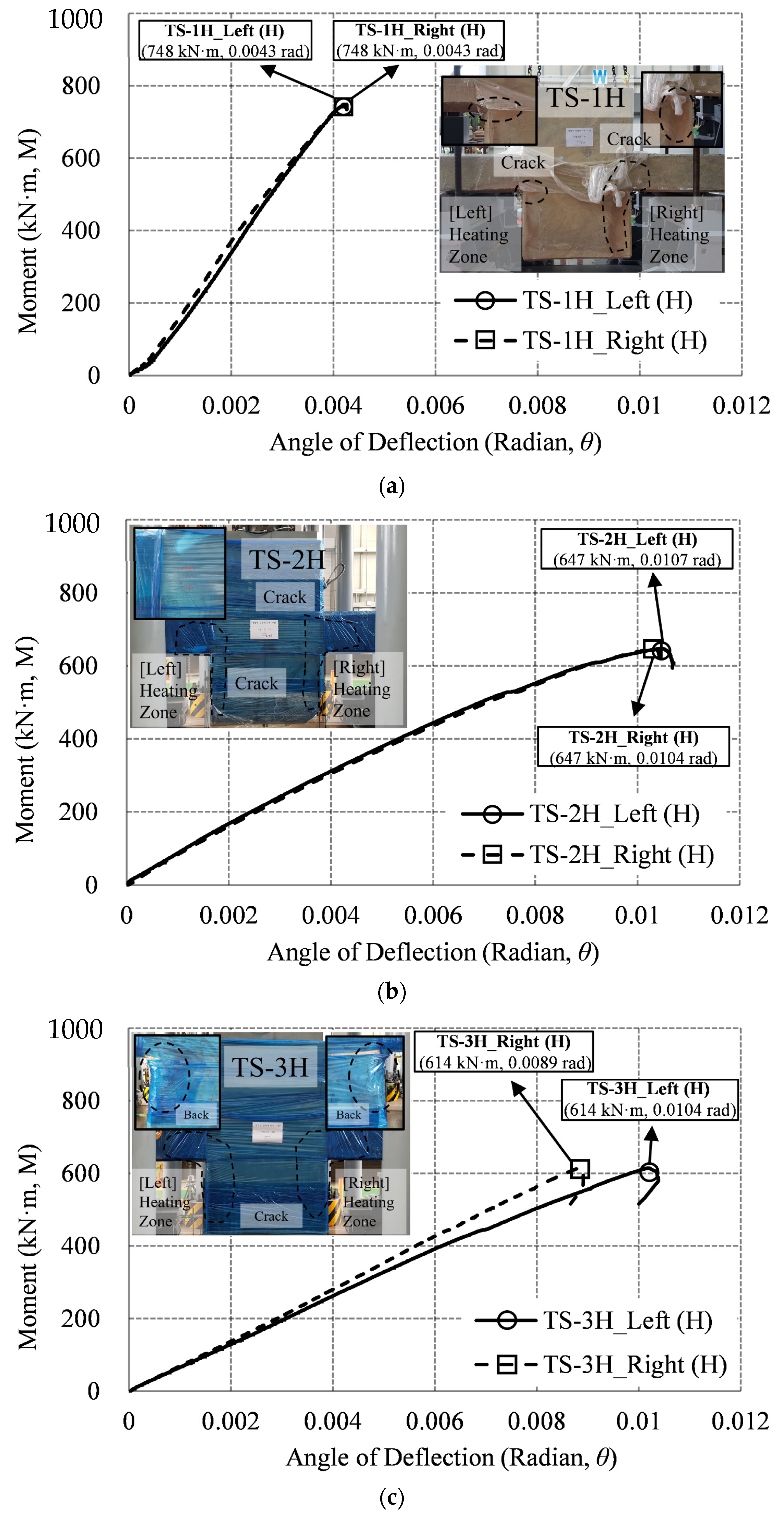
3.3.4. Result of the Moment–Deflection Angle
4. Comparison of the Experimental Results and Standards
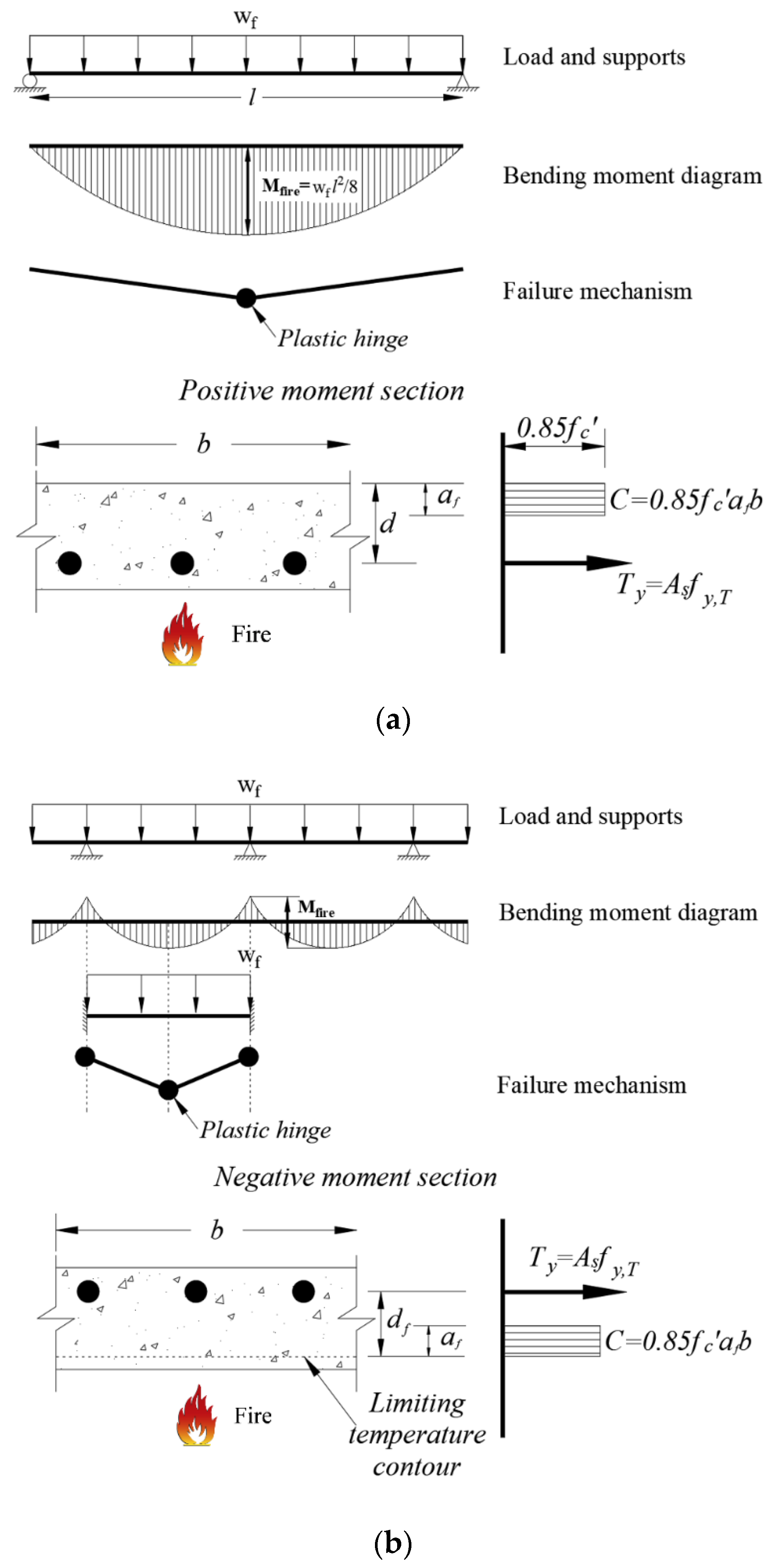
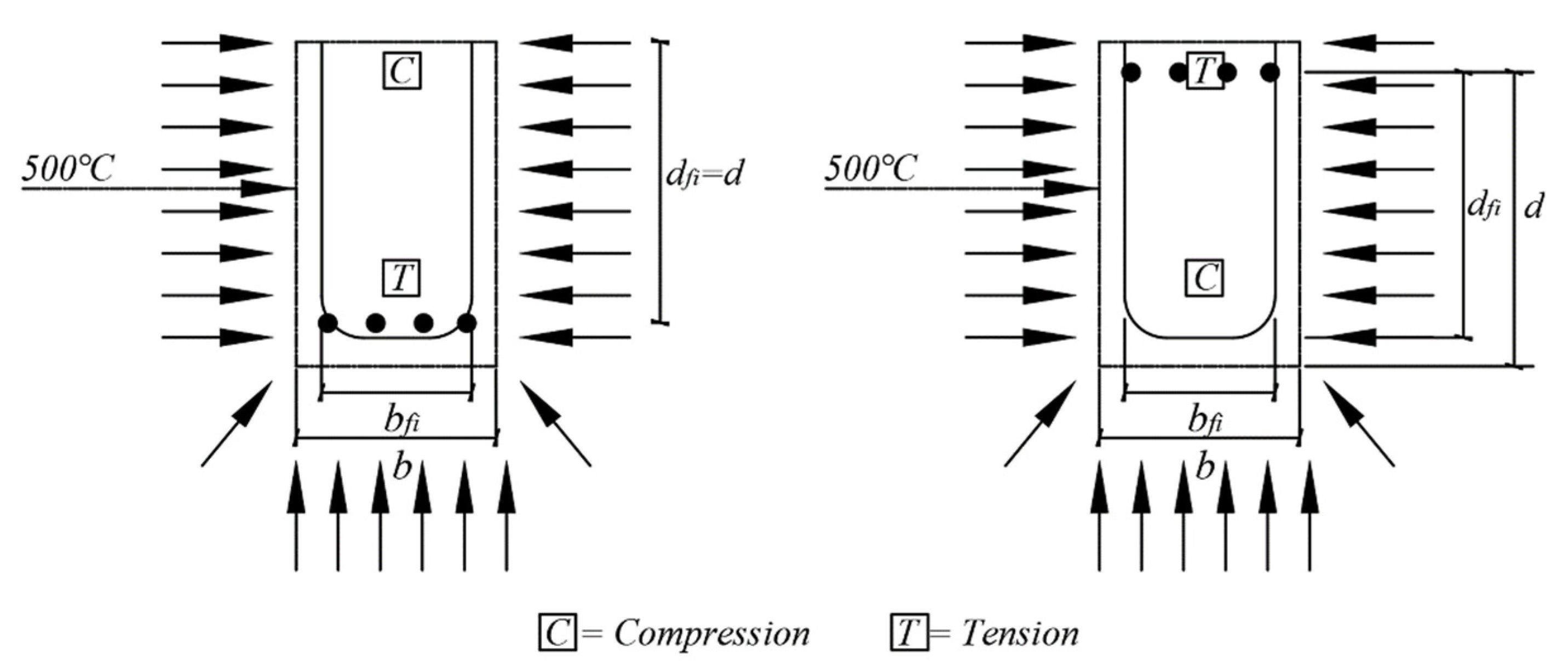
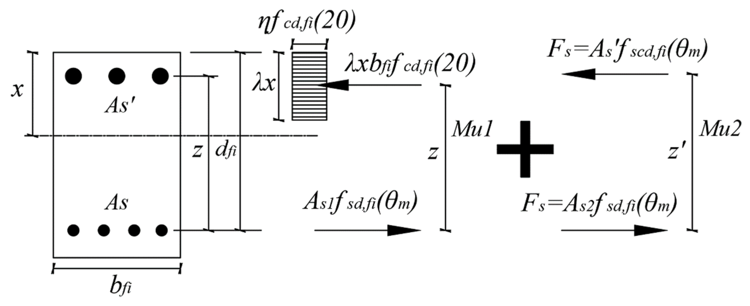
4.1. Eurocode’s Simplified Calculations Method
4.2. Nist’s Simplified Calculations Method
4.3. ACI’s Simplified Calculations Method
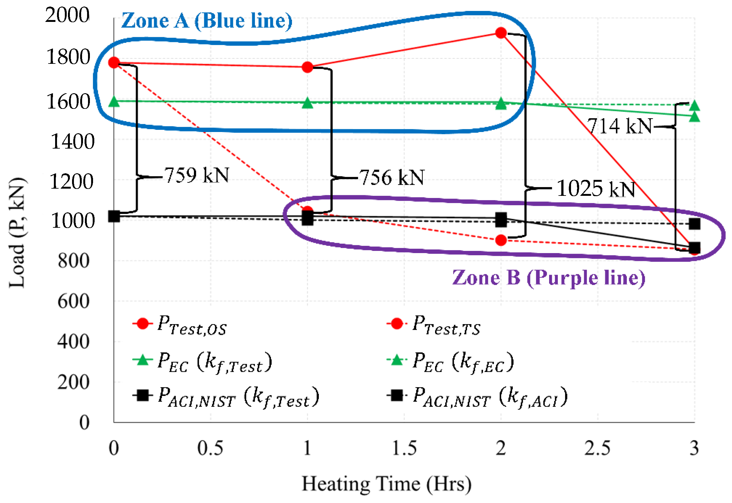
4.4. Comparison of Simplified Calculation Methods and Experimental Results
5. Conclusions
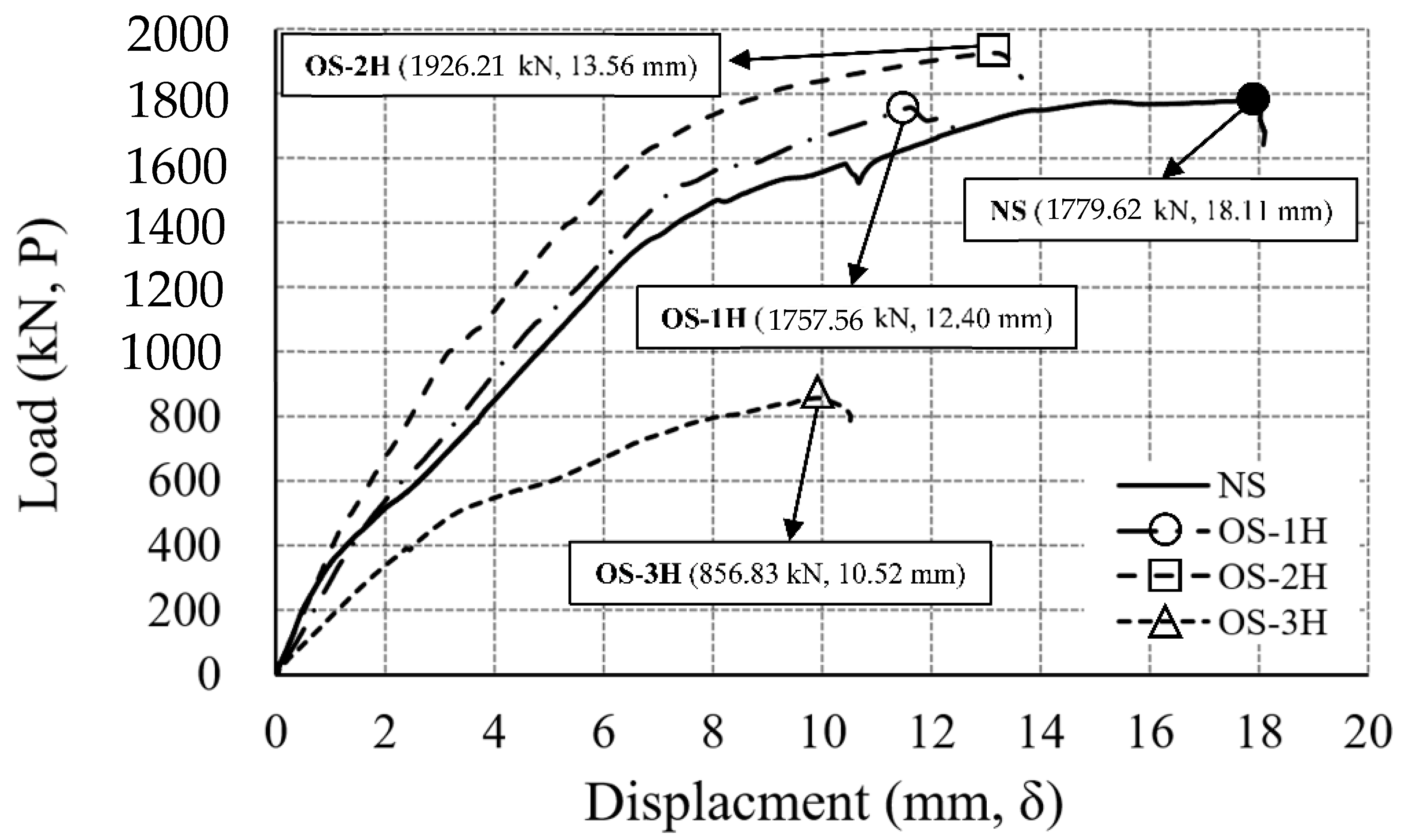
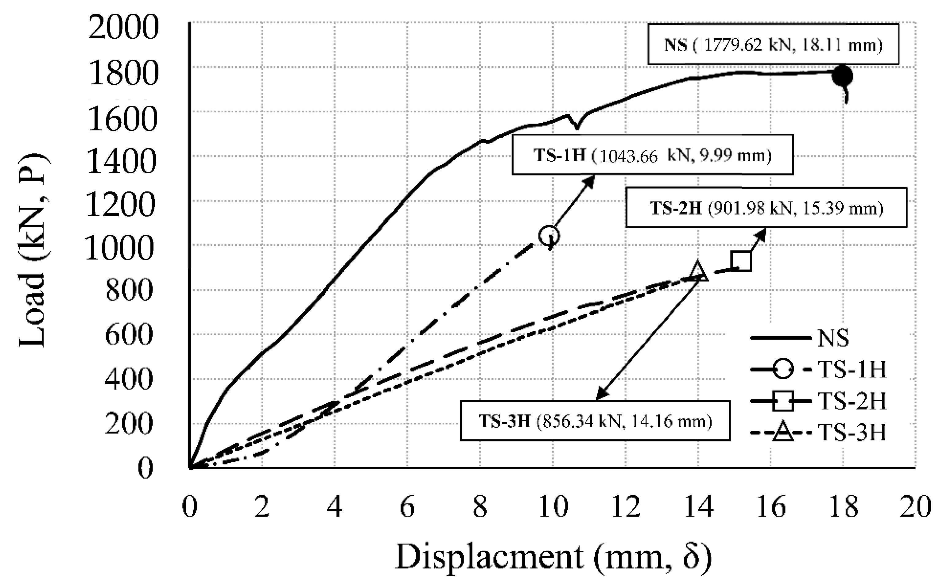
- As compared with the non-heating specimen, in 1 h heating, the one-sided heating specimen showed no decrease in strength. In 2 h heating, the strength increased by more than about 8%. However, at 3 h heating, the strength decreased notably by over 52%. In the case of 2 h heating, the temperature of the slab rebar was about 245 °C, and the temperature of the connection rebar was 445 °C. It was identified that the strength of rebars partially cooled at the temperatures of 200 to 500 °C recovered. Therefore, the strength of the one-sided heating specimen in 2 h of heating increased slightly compared to the room temperature specimen. However, the strength of the two-sided heating specimen was reduced by 41% in 1 h of heating, when compared to the NS. At 2 h of heating, strength decreased by more than 49%; and at 3 h of heating, the strength decreased by more than about 52% in sharp rate.
- Compared to the one-sided heating test, the strength of the two-sided heating test specimen decreased by more than 2 times in both 1 h and 2 h. However, in the 3 h fire, both the one-sided and two-sided test specimens showed a strength reduction by more than twice (52%), compared to the non-heating specimens. In the 3 h fire rates, the maximum load of one-sided, two-sided specimen and the maximum moment of one-sided, two-sided specimen were 856 kN and 614 kN·m, respectively. Therefore, in a 3 h fire, the strength decreased by more than 2 times compared to the non-heating specimens, regardless of the fire scenario (one-sided, two-sided). Therefore, in a fire for a long time of 3 h or more, it is necessary to secure sufficient size and strength of members regardless of the fire scenario.
- Compared to the two-sided fire scenario, there was a different deflection angle between fired Zone 1 and non-fired Zone 2 in the one-sided fire scenario. The difference between the left and right maximum deflection angles in one-sided specimen was about 0.01029 rad in a 3 h fire. On the other hand, the difference between the maximum left and right deflection angles in two-sided specimen was found to be 0.00147 rad in a 3 h fire. The maximum deflection angle of two-sided specimen was seven times greater than that of one-sided specimen. Compared to the two-sided specimen, it can be interpreted as the significant difference in the deflection angle could be occurred at the left and right connection areas in the one-sided specimen, due to the unbalance fire strength.
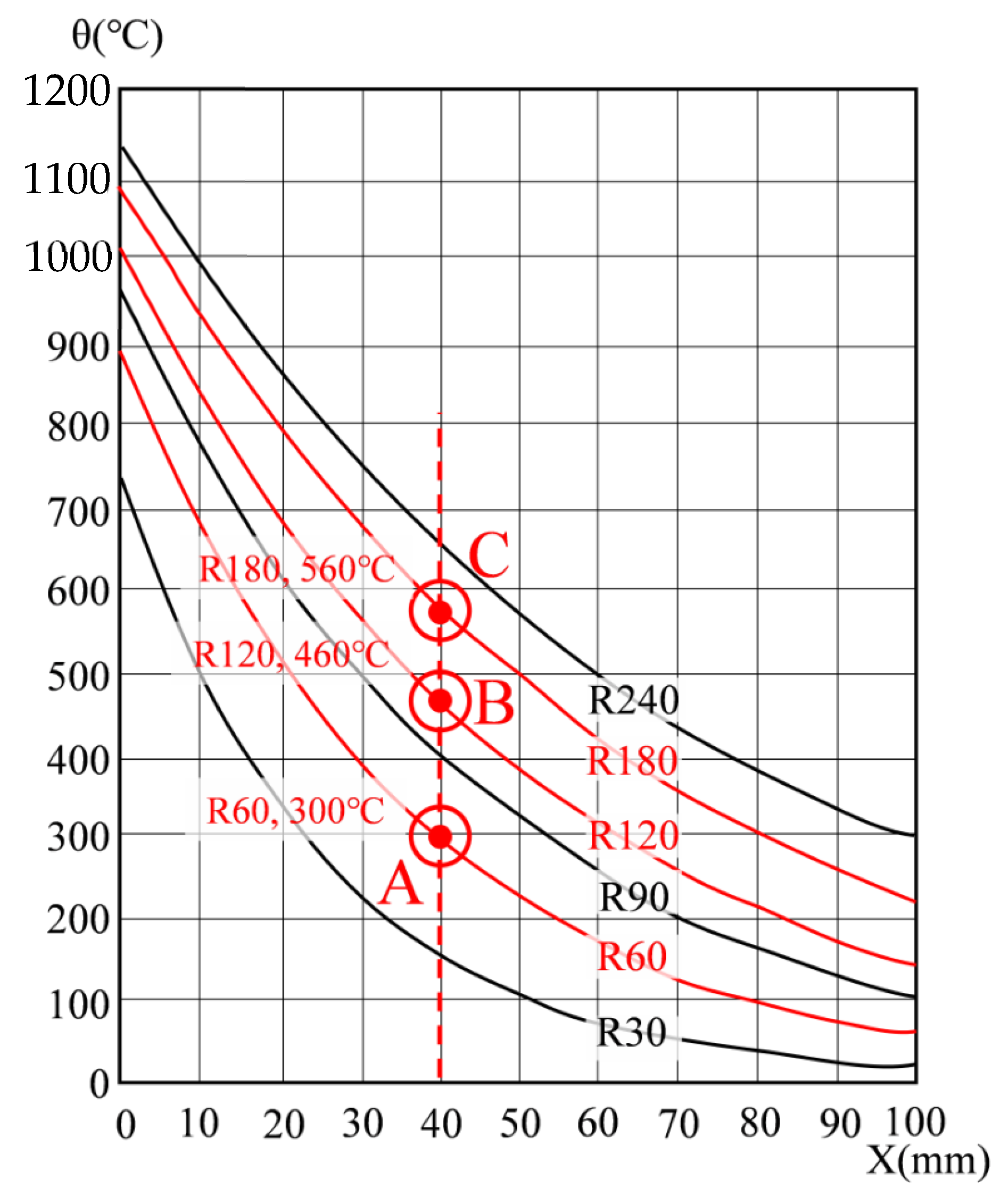
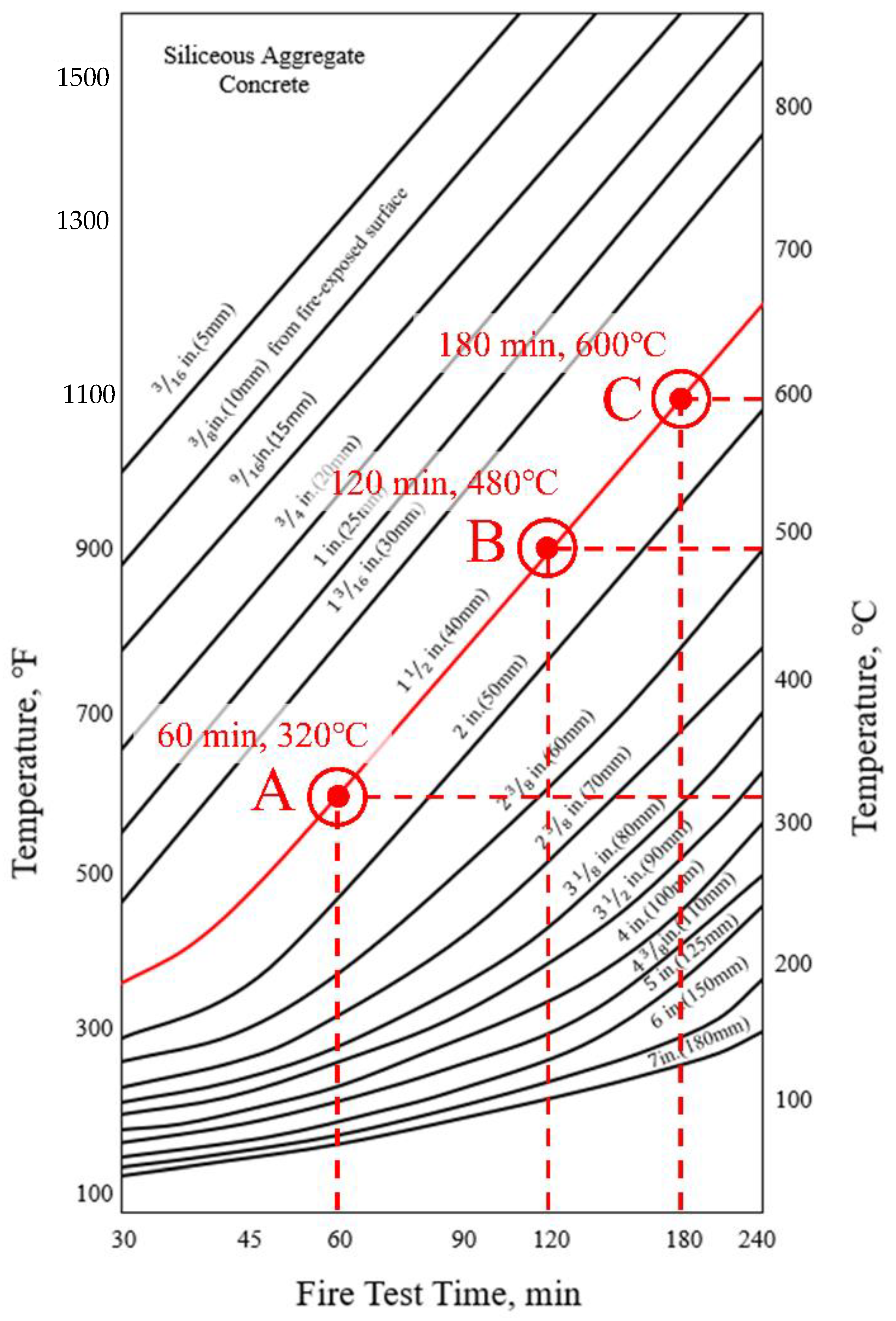
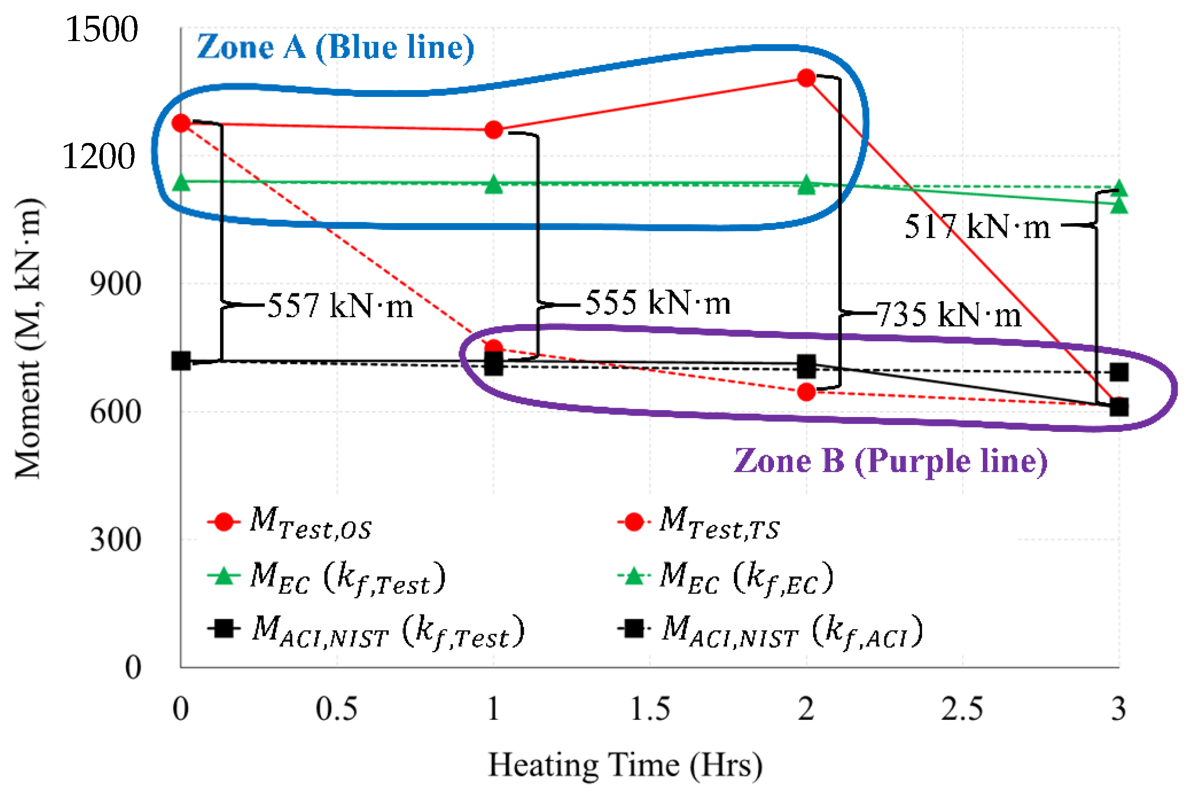
- As a result of comparing the fire tests with the simple calculation results of the standards (Eurocode, ACI) and NIST, the one-sided fire scenario is located in Zone A (see Figure 22 and Figure 23) well agreed to the results of Eurocode 1992-1-2. The two-sided fire scenario is located in Zone B (see Figure 22 and Figure 23), similar to the results of ACI 216 1M-14 (NIST 1681). The maximum load difference between the one-sided and two-sided tests was about 1025 kN in the 2 h heating, and the maximum moment difference was about 735 kN·m in the 2 h heating test.
- The maximum moments and strengths by Eurocode’s simplified calculation showed similar results to the one-sided heating test result. The simplified calculation results both ACI and NIST showed similar results to the two-sided heating test. As a result of comparisons between Zone A and Zone B in one side scenario, the residual strength at the connection after the fire can be inferred according to the Eurocode equation. In a fire scenario where a two-sided heating situation occurs, the residual strength of the connection after the fire can be inferred according to the equations of ACI and NIST. In the future performance-based fire design, the criteria that consider the fire-exposed surface should be reflected in consideration of the fire scenario.
Author Contributions
Funding
Informed Consent Statement
Data Availability Statement
Acknowledgments
Conflicts of Interest
Abbreviations
| Cross-sectional area of non-prestressed longitudinal tension reinforcement (rebar) | () | |
| Area of compression reinforcement (rebar) | () | |
| Area of tensile steel provided | () | |
| Area of tensile steel required for design at ambient temperature to EN1992-1-1 | () | |
| Part of tension reinforcement in equilibrium with the concrete compression block | () | |
| Part of tension reinforcement in equilibrium with the compression reinforcement (rebar) | () | |
| , | Depth of equivalent concrete rectangular stress block at elevated temperature | () |
| Width of concrete slab or beam | () | |
| Width of the fire exposed cross-section | () | |
| Compressive force | () | |
| Effective depth, distance from centroid of tension reinforcement (rebar) to extreme compressive fiber or depth of steel column | () | |
| Effective depth of the slab, reduced to allow for the hot layer of concrete on the bottom surface | () | |
| Efficient height of the fire exposed cross-section | () | |
| Elastic modulus of concrete | () | |
| Elastic modulus of concrete at elevated temperature | () | |
| Elastic modulus of concrete at 20 °C | () | |
| Elastic modulus of reinforcing steel bar (rebar) | () | |
| Elastic modulus of reinforcing steel bar (rebar) at elevated temperature | () | |
| Elastic modulus of reinforcing steel bar (rebar) at 20 °C | () | |
| Total force in compression reinforcement in the fire situation, and is equal to part of the total force in the tension reinforcement | () | |
| Specified compressive strength of concrete | () | |
| Compressive strength of concrete at elevated temperature | () | |
| Compressive strength of concrete at 20 °C | () | |
| Design value of the compression strength concrete in the fire situation at normal temperature | () | |
| Yield strength of reinforcing steel bar (rebar) | () | |
| Yield strength of reinforcing steel bar (rebar) at 20 °C | () | |
| , | Reduced yield strength of non-prestressed reinforcing steel bar (rebar) at elevated temperature | () |
| Design value of the tension reinforcement strength in the fire situation at mean temperature in that layer | () | |
| Design value of the compression reinforcement strength in the fire situation at mean temperature in that layer | () | |
| Ultimate strength of reinforcing steel bar (rebar) at 20 °C | () | |
| Heating zone | - | |
| Slab thickness | () | |
| Reduction factor | - | |
| Elastic modulus reduction factor of concrete or reinforcing steel bar (rebar) according to ACI216.1M-14 | - | |
| Elastic modulus reduction factor of concrete or reinforcing steel bar (rebar) according to EN1992-1-2 | - | |
| Elastic modulus reduction factor of concrete or reinforcing steel bar (rebar) according to fire test | ||
| Yield strength reduction factor of concrete or reinforcing steel bar (rebar) according to ACI216.1M-14 | - | |
| Yield strength reduction factor of concrete or reinforcing steel bar (rebar) according to EN1992-1-2 | - | |
| Yield strength reduction factor of concrete or reinforcing steel bar (rebar) according to fire test | - | |
| Steel strength reduction factor for the given temperature | - | |
| Clear span between supports | () | |
| Effective length of beam or slab | () | |
| Short side length | () | |
| Long side length | () | |
| Moment | () | |
| Applied moment for cold design to EN1992-1-1 | () | |
| Maximum fire design moment to EN1992-1-2 | () | |
| Flexural capacity in fire conditions | () | |
| Maximum flexural capacity | () | |
| Moment of the non-heating specimen (NS) | () | |
| Flexural capacity of member at elevated temperature | () | |
| Positive flexural capacity of member at elevated temperature | () | |
| Moment resistance | () | |
| Moment in related to the area and strength of the tension rebar | () | |
| Moment in related to the area and strength of the compression rebar | () | |
| Non-heating zone | - | |
| Design axial load in the fire situation | () | |
| Design resistance of the wall (column) at normal temperature conditions | () | |
| Load of the actuator | () | |
| Load of the non-heating specimen (NS) | () | |
| Room temperature | °C | |
| Uniformly distributed load under fire conditions | () | |
| Uniformly distributed load on beam in fire conditions | () | |
| Temperature | °C | |
| Temperature of in EN1992-1-2 | °C | |
| Temperature of in ACI216.1M-14 | °C | |
| Temperature of thermocouple in test | °C | |
| Tension force at yield | () | |
| Effective fire exposure depth of the rebar | ||
| Reduction factor for the design load level in the fire situation | - | |
| Neutral axis depth | () | |
| Lever arm between the tension reinforcement and concrete | () | |
| Lever arm between the tension and compression reinforcement | () | |
| Partial material factor for steel used in EN1992-1-1 | - | |
| Partial material factor for steel under fire conditions in EN1992-1-1 | - | |
| Displacement in the average value of LVDT | () | |
| Deflection angle | () | |
| Maximum deflection angle | () |
References
- Hwang, J.Y.; Kwak, H.G. A numerical model of reinforced concrete members exposed to fire and after-cooling analysis. J. Comput. Struct. Eng. Inst. Korea 2015, 28, 101–113. [Google Scholar]
- Albrektsson, J.; Flansbjer, M.; Lindqvust, J.E.; Jansson, R. Assessment of Concrete Structures after Fire; SP Technical Research Institute of Sweden: Borås, Sweden, 2001; pp. 9–10. [Google Scholar]
- Choi, K.H. Evaluation techniques for residual structural performance of a reinforced concrete slab under fire damage. J. Korea Acad. Ind. Coop. Soc. 2020, 21, 588–594. [Google Scholar]
- Khoury, G.A. Effect of fire on concrete and concrete structures. Progr. Struct. Eng. Mater. 2000, 2, 429–447. [Google Scholar] [CrossRef]
- Wang, Y.; Burgess, I.; Wald, F.; Gillie, M. Performance-Based Fire Engineering of Structures; John Wiley & Sons Inc.: New York, NY, USA, 2012. [Google Scholar]
- Buchhanan, A.H. Structural Design for Fire Safety; CRC Press: New York, NY, USA, 2017. [Google Scholar]
- Kodur, V.K.R.; Dwaikat, M. A numerical model for predicting the fire resistance of reinforced concrete beams. Cem. Concr. Comp. 2008, 30, 431–443. [Google Scholar] [CrossRef]
- Guo, S.; Bailey, C.G. Experimental behaviour of composite slabs during the heating and cooling fire stages. Eng. Struct. 2011, 33, 563–571. [Google Scholar] [CrossRef]
- Li, L.Z.; Liu, X.; Yu, J.T.; Lu, Z.D.; Su, M.N.; Liao, J.H.; Xia, M. Experimental study on seismic performance of post-fire reinforced concrete frames. Eng. Struct. 2019, 179, 161–173. [Google Scholar] [CrossRef]
- Li, G.Q.; Guo, S.X. Experiment on restrained steel beams subjected to heating and cooling. J. Constr. Steel Res. 2008, 64, 268–274. [Google Scholar] [CrossRef]
- Wang, Y.; Yuan, G.; Huang, Z.; Lyu, J.; Li, Q.; Long, B. Modelling of reinforced concrete slabs in fire. Fire Saf. J. 2018, 100, 171–185. [Google Scholar] [CrossRef]
- Kodur, V.K.R.; Dwaikat, M.B.; Fike, R.S. An approach for evaluating the residual strength of fire-exposed RC beams. Mag. Concr. Res. 2010, 62, 479–488. [Google Scholar] [CrossRef]
- Choi, H.K.; Chung, J.H.; Choi, C.S. Estimation method of residual performance for hollow slab at elevated temperature. J. Korea Concr. Inst. 2014, 26, 643–650. [Google Scholar] [CrossRef] [Green Version]
- Liao, F.; Hyang, Z. An extended finite element model for modelling localized fracture of reinforced concrete beams in fire. Comput. Struct. 2015, 152, 11–26. [Google Scholar] [CrossRef] [Green Version]
- Vecchio, F.J.; Shim, W. Experimental and analytical reexamination of classic concrete beam tests. J. Struct. Eng. 2004, 130, 460–469. [Google Scholar] [CrossRef] [Green Version]
- Sucharda, O.; Konecny, P. Recommendation for the modelling of 3D non-linear analysis of RC beam tests. Comput. Concr. 2018, 21, 11–20. [Google Scholar]
- EN 1992-1-2 Eurocode 2: Design of Concrete Structures—Part 1–2: General Rules–Structural Fire Design; Comité Européen de Normalisation: Brussels, Belgium, 2005.
- ACI 216.1M-14: Code Requirements for Determining Fire Resistance of Concrete and Masonry Construction Assemblies; American Concrete Institute: Chicago, IL, USA, 2017.
- NIST Technical Note 1681: Best Practice Guidelines for Structural Fire Resistance Design of Concrete and Steel Buildings; National Institute of Standards and Technology (NIST): Gaithersburg, MD, USA, 2010.
- Elghazouli, A.Y.; Cashell, K.A.; Izzuddin, B.A. Experimental evaluation of the mechanical properties of steel reinforcement at elevated temperature. Fire Saf. J. 2009, 44, 909–919. [Google Scholar] [CrossRef] [Green Version]
- Lee, J.W. Elevated Temperature Properties of Astm A992 Steel for Structural-Fire Engineering Analysis. Ph.D. Thesis, University of Texas, Austin, TX, USA, 2012. [Google Scholar]
- Nassif, A. Postfire full stress–strain response of fire-damaged concrete. Fire Mater. 2006, 30, 323–332. [Google Scholar] [CrossRef]
- Chang, Y.F.; Chen, Y.H.; Sheu, M.S.; Yao, G.C. Residual stress–strain relationship for concrete after exposure to high temperatures. Cem. Concr. Res. 2006, 36, 1999–2005. [Google Scholar] [CrossRef]
- Kodur, V.K.R. Properties of concrete at elevated temperatures. ISRN Civ. Eng. 2014, 2014, 1–15. [Google Scholar] [CrossRef]
- ASTM C 39 / C39 M-20: Compressive Strength of Cylindrical Concrete Specimens; American Society for Testing and Materials (ASTM): Pennsylvania, PA, USA, 2020.
- Kim, G.Y.; Kang, Y.W.; Lee, T.G.; Choe, G.C.; Yoon, M.H. An experimental study on the mechanical properties of concrete with high temperatures and cooling conditions. J. Korea Inst. Build. Constr. 2012, 12, 323–331. [Google Scholar] [CrossRef] [Green Version]
- Kee, S.H.; Kang, J.W.; Choi, B.J.; Kwon, J.H.; Candelaria, M.D. Evaluation of static and dynamic residual mechanical properties of heat-damaged concrete for nuclear reactor auxiliary buildings in korea using elastic wave velocity measurements. Materials 2019, 12, 2695. [Google Scholar] [CrossRef] [PubMed] [Green Version]
- Gunalan, S.; Mahendran, M. Experimental investigation of post-fire mechanical properties of cold-formed steels. Thin Wall. Struct. 2014, 84, 241–254. [Google Scholar] [CrossRef] [Green Version]
- Choi, I.R.; Chung, K.S. Residual strength of structural steels: SN400, SM520 and SM570. In Proceedings of the International Conference in Dubrovnik, Dubrovnik, Croatia, 15–16 October 2015. [Google Scholar]
- Qiang, X.; Bijlaard, F.S.K.; Kolstein, H. Post-fire mechanical properties of high strength structural steels S460 and S690. Eng. Struct. 2012, 35, 1–10. [Google Scholar] [CrossRef]
- Felicetti, R.; Gambarova, P.G.; Meda, A. Residual behavior of steel rebars and R/C sections after a fire. Constr. Build. Mater. 2009, 23, 3546–3555. [Google Scholar] [CrossRef]
- Aziz, E.; Kodur, V.K.R. Effect of temperature and cooling regime ons mechanical properties of high-strength low-allow steel. Fire Mater. 2016, 40, 926–939. [Google Scholar] [CrossRef]
- Wang, W.; Liu, T.; Liu, J. Experimental study on post-fire mechanical properties of high strength Q460 steel. J. Constr. Steel Res. 2015, 114, 100–109. [Google Scholar] [CrossRef]
- NIST GCR 02-843-1 (Revision): Analysis of Needs and Existing Capabilities for Full-Scale Fire Resistance Testing; National Institute of Standards and Technology (NIST): Gaithersburg, MD, USA, 2008.
- ASTM E119-15. Standard Test. In Method for Fire Test of Building Construction and Materials; American Society for Testing and Materials: West Conshohocken, PA, USA, 2015. [Google Scholar]


| Compressive Strength | Elastic Modulus | |||||||
|---|---|---|---|---|---|---|---|---|
| Standard Deviation | Standard Deviation | |||||||
| 20 | 40.80 | 0.81 | 41.93 () | 1.00 | 24,200 | 927.36 | 23,700 () | 1.00 |
| 42.40 | 22,400 | |||||||
| 42.60 | 24,500 | |||||||
| 100 | 38.30 | 0.22 | 38.00 | 0.91 | 22,000 | 974.11 | 20,633 | 0.87 |
| 37.90 | 20,100 | |||||||
| 37.80 | 19,800 | |||||||
| 200 | 35.30 | 0.65 | 35.30 | 0.84 | 18,000 | 531.25 | 18,033 | 0.76 |
| 36.10 | 17,400 | |||||||
| 34.50 | 18,700 | |||||||
| 300 | 28.40 | 1.64 | 28.13 | 0.67 | 12,800 | 294.39 | 12,400 | 0.52 |
| 26.00 | 12,300 | |||||||
| 30.00 | 12,100 | |||||||
| 400 | 27.40 | 1.51 | 25.83 | 0.62 | 9900 | 402.77 | 9333 | 0.39 |
| 26.30 | 9000 | |||||||
| 23.80 | 9100 | |||||||
| 500 | 19.80 | 1.06 | 21.10 | 0.50 | 5300 | 355.90 | 5800 | 0.24 |
| 22.40 | 6100 | |||||||
| 21.10 | 6000 | |||||||
| 600 | 16.30 | 0.82 | 15.93 | 0.38 | 1700 | 163.30 | 1900 | 0.08 |
| 16.70 | 2100 | |||||||
| 14.80 | 1900 | |||||||
| 700 | 11.90 | 0.22 | 11.80 | 0.28 | 1100 | 124.72 | 1233 | 0.05 |
| 11.50 | 1400 | |||||||
| 12.00 | 1200 | |||||||
| 800 | 7.90 | 0.33 | 8.30 | 0.20 | 1000 | 47.14 | 933 | 0.04 |
| 8.70 | 900 | |||||||
| 8.30 | 900 | |||||||
| 900 | 4.20 | 0.28 | 3.80 | 0.09 | 500 | 47.14 | 433 | 0.02 |
| 3.60 | 400 | |||||||
| 3.60 | 400 | |||||||
| 1000 | 2.50 | 0.26 | 2.63 | 0.06 | 300 | 47.14 | 233 | 0.01 |
| 3.00 | 200 | |||||||
| 2.40 | 200 | |||||||
| Residual Elastic Modulus | |||||||||||||||||||||
|---|---|---|---|---|---|---|---|---|---|---|---|---|---|---|---|---|---|---|---|---|---|
| G300 [28] (Strain Level, %) | SN400 [29] (Strain Level, %) | S460 [30] (Strain Level, %) | Carbon Steel [31] | A572 Gr.50 [32] | A992 [21] | Q460 [30] | Average | Average | |||||||||||||
| SM | HB | ||||||||||||||||||||
| 0.2 | 0.5 | 1.5 | 2.0 | 0.2 | 0.5 | 1.5 | 2.0 | 0.2 | 0.5 | 1.5 | 2.0 | Φ24 | Φ18 | Φ29 | Φ9 | ||||||
| 20 | 1.00 | 1.00 | 1.00 | 1.00 | 1.00 | 1.00 | 1.00 | 1.00 | 1.00 | 1.00 | 1.00 | 1.00 | 1.00 | 1.00 | 1.00 | 1.00 | 1.00 | 1.00 | 1.00 | 1.00 | 1.00 |
| 100 | 1.00 | 1.00 | 1.00 | 1.00 | 0.97 | 0.96 | 0.96 | 0.99 | 1.00 | 1.00 | 1.00 | 1.00 | 0.99 | 1.00 | 1.00 | 1.00 | 1.01 | 1.00 | 1.00 | 0.99 | |
| 200 | 1.00 | 1.00 | 1.00 | 1.00 | 0.98 | 0.98 | 0.98 | 0.99 | 1.00 | 1.00 | 1.00 | 1.00 | 0.99 | 0.99 | 1.01 | 1.01 | 1.03 | 0.97 | 1.00 | 1.00 | |
| 300 | 0.92 | 0.92 | 0.92 | 0.92 | 0.97 | 0.97 | 0.97 | 0.98 | 1.00 | 1.00 | 1.01 | 1.00 | 0.95 | 0.99 | 1.02 | 0.99 | 1.04 | 1.01 | 1.06 | 0.98 | |
| 400 | 0.92 | 0.91 | 0.92 | 0.92 | 0.97 | 0.97 | 0.97 | 0.98 | 1.00 | 0.99 | 1.01 | 0.95 | 0.91 | 0.98 | 1.02 | 0.95 | 1.06 | 0.99 | 1.05 | 0.97 | |
| 500 | 0.87 | 0.87 | 0.86 | 0.86 | 0.99 | 0.99 | 0.98 | 1.00 | 1.01 | 1.01 | 1.00 | 0.97 | 0.92 | 0.98 | 0.99 | 1.00 | 1.03 | 1.02 | 1.05 | 0.97 | |
| 600 | 0.88 | 0.88 | 0.88 | 0.88 | 0.99 | 0.98 | 0.97 | 0.99 | 0.98 | 0.97 | 1.01 | 0.97 | 0.92 | 0.98 | 0.99 | 0.90 | 1.00 | 1.02 | 1.04 | 0.96 | |
| 700 | 0.72 | 0.73 | 0.75 | 0.75 | 0.97 | 0.97 | 0.97 | 0.98 | 0.97 | 0.96 | 0.96 | 0.90 | 0.89 | 0.78 | 0.79 | 0.79 | 0.72 | 0.98 | 1.00 | 0.87 | |
| 800 | - | - | - | - | 0.90 | 0.91 | 0.91 | 0.91 | 0.87 | 0.86 | 0.89 | 0.82 | 0.85 | 0.79 | 0.81 | 0.72 | 0.60 | 0.91 | 0.80 | 0.84 | |
| 900 | - | - | - | - | 0.98 | 0.98 | 0.97 | 0.98 | 0.87 | 0.86 | 0.87 | 0.81 | 0.82 | 0.80 | 0.82 | 0.64 | 0.53 | 0.89 | 0.73 | 0.84 | |
| 1000 | - | - | - | - | - | - | - | - | 0.76 | 0.76 | 0.79 | 0.76 | - | - | - | - | 0.45 | 0.86 | - | 0.73 | |
| Standard Fire Resistance | Minimum Dimensions (mm) Wall Thickness/Axis Distance for | |||
|---|---|---|---|---|
| Wall Exposed on One Side | Wall Exposed on Two Sides | Wall Exposed on One Side | Wall Exposed on Two Sides | |
| 1 | 2 | 3 | 4 | 5 |
| REI 30 | 100/10 * | 120/10 * | 120/10 * | 120/10 * |
| REI 60 | 110/10 * | 120/10 * | 120/10 * | 140/10 * |
| REI 90 | 120/10 * | 140/10 * | 140/25 | 170/25 |
| REI 120 | 150/25 | 160/25 | 160/35 | 220/35 |
| REI 180 | 180/40 | 200/45 | 210/50 | 270/55 |
| REI 240 | 230/55 | 250/55 | 270/60 | 350/60 |
| Section of Wall-Slab Connection | |||
|---|---|---|---|
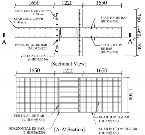 | |||
| Material | Properties | ||
| Rebar (SD400) | Yield,(MPa) | 400~520 | |
| Ultimate,(MPa) | |||
| Diameter (mm) | Slab top, wall | 32 (D32) | |
| Slab bottom | 25 (D22) | ||
| Concrete | Compression,(MPa) | 35 | |
| Slump (mm) | 120 | ||
| Aggregates type | Siliceous | ||
| Standard Fire Resistance | Minimum Dimensions (mm) Wall Thickness/Axis Distance for | |||
|---|---|---|---|---|
| Axis-Distance | ||||
| One Way | Two Way | |||
| 1 | 2 | 3 | 4 | 5 |
| REI 30 | 60 | 10* | 10 * | 10 * |
| REI 60 | 80 | 20 | 10 * | 15 * |
| REI 90 | 100 | 30 | 15 * | 20 |
| REI 120 | 120 | 40 | 20 | 25 |
| REI 180 | 150 | 55 | 30 | 40 |
| REI 240 | 175 | 65 | 40 | 50 |
| Aggregate Type | Minimum Equivalent Thickness for Fire-Resistance Rating, mm | ||||
|---|---|---|---|---|---|
| 1 h | 1–1/2 h | 2 h | 3 h | 4 h | |
| Siliceous | 90 | 110 | 125 | 155 | 175 |
| Carbonate | 80 | 100 | 115 | 145 | 170 |
| Aggregate Type | Minimum Equivalent Thickness for Fire-Resistance Rating, mm | |||||
|---|---|---|---|---|---|---|
| Restrained | Unrestrained | |||||
| 4 or Less | 1 h | 1–1/2 h | 2 h | 3 h | 4 h | |
| Non-Prestressed | ||||||
| Siliceous | 20 | 20 | 20 | 25 | 30 | 40 |
| Carbonate | 20 | 20 | 20 | 20 | 30 | 30 |
| Prestressed | ||||||
| Siliceous | 20 | 30 | 40 | 45 | 60 | 70 |
| Carbonate | 20 | 25 | 35 | 40 | 55 | 55 |
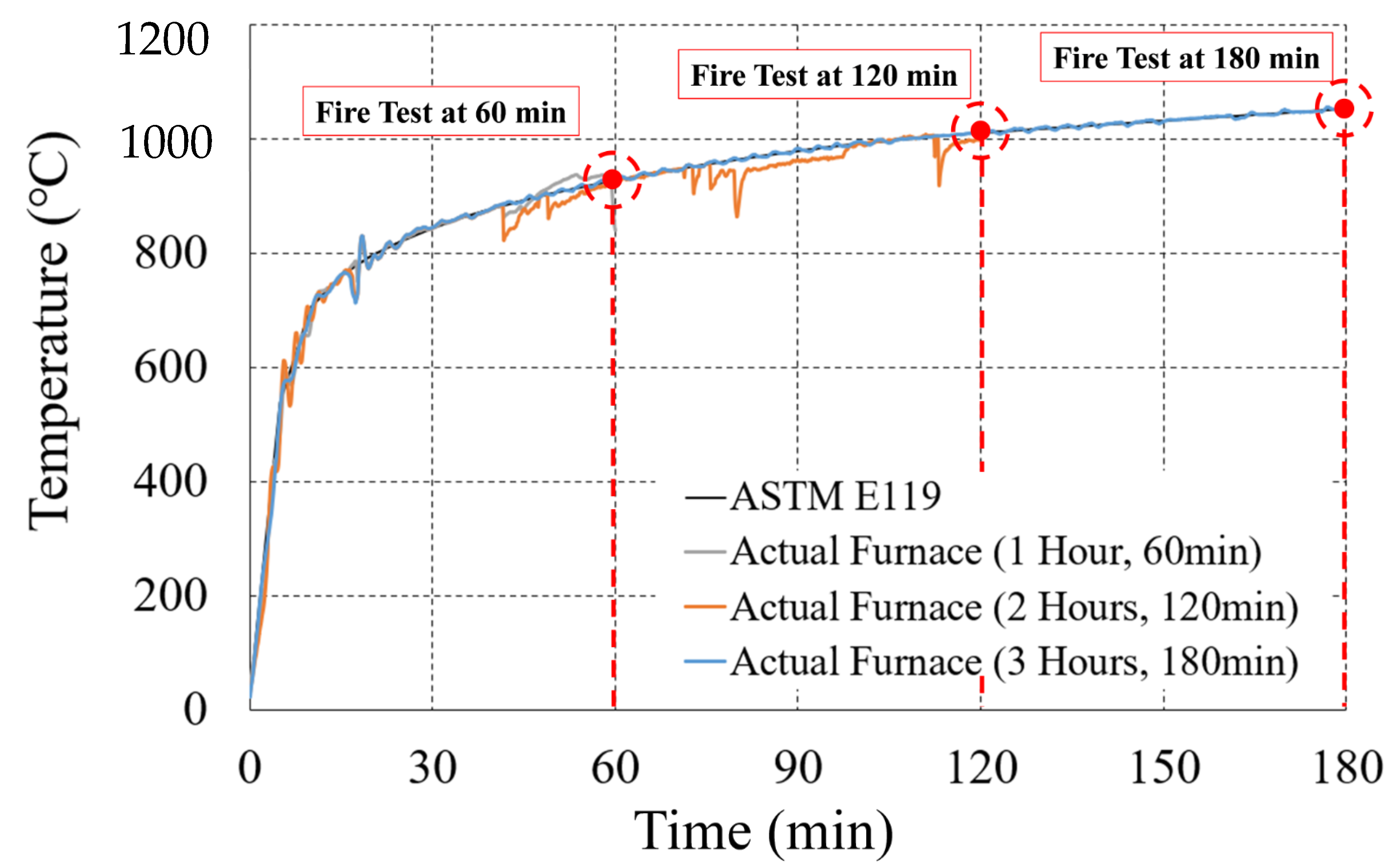
| Specimen | Fire Scenario | Fire Curve | Heating Time | Manufacture (EA) |
|---|---|---|---|---|
| NS | Non-heating | ASTM E119 | 0 | 1 |
| OS-1H | One-side heating | 1 | 1 | |
| OS-2H | 2 | 1 | ||
| OS-3H | 3 | 1 | ||
| TS-1H | Two-side heating | 1 | 1 | |
| TS-2H | 2 | 1 | ||
| TS-3H | 3 | 1 |
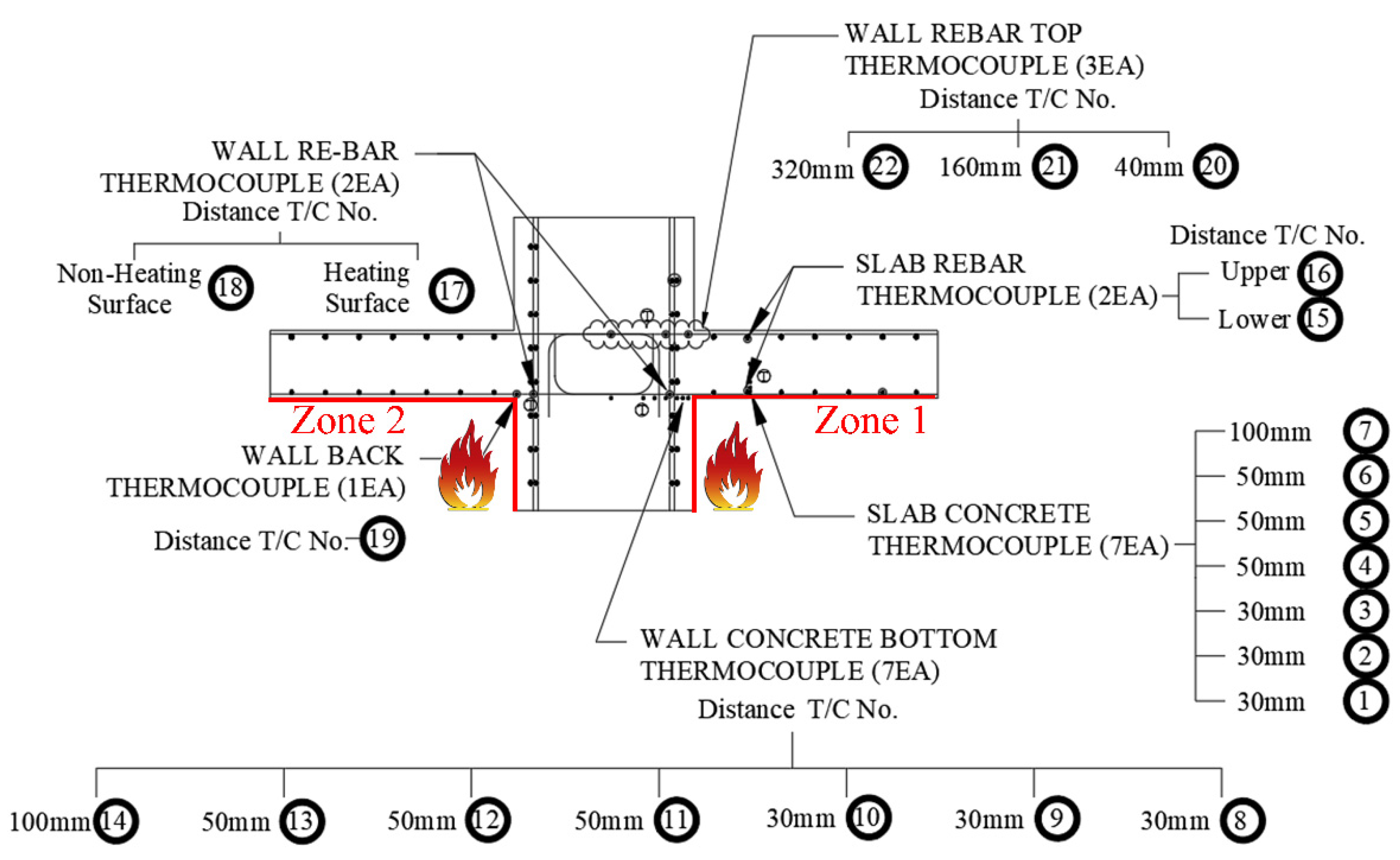
| T/C No. | Concrete Cover of Exposed to Fire (mm) | Max Temperature (°C) | ||||||
|---|---|---|---|---|---|---|---|---|
| 1 h (60 min) | 2 h (120 min) | 3 h (180 min) | ||||||
| OS | TS | OS | TS | OS | TS | |||
| Slab | ||||||||
| 1 | 30 | 250 | 34 | 333 | 89 | 1061 | 124 | |
| 2 | 60 | 134 | 30 | 192 | 68 | 783 | 114 | |
| 3 | 80 | 110 | 28 | 122 | 55 | 674 | 92 | |
| 4 | 140 | 49 | 27 | 100 | 37 | 579 | 46 | |
| 5 | 190 | 29 | 27 | 77 | 31 | 326 | 31 | |
| 6 | 240 | 26 | 27 | 42 | 28 | 671 | 28 | |
| 7 | 340 | 26 | 27 | 25 | 27 | 549 | 27 | |
| Wall | ||||||||
| 8 | 30 | 152 | 208 | 128 | 216 | 218 | 389 | |
| 9 | 60 | 109 | 121 | 113 | 107 | 143 | 219 | |
| 10 | 90 | 100 | 108 | 74 | 137 | 111 | 135 | |
| 11 | 140 | 33 | 84 | 29 | 64 | 64 | 102 | |
| 12 | 190 | 24 | 38 | 25 | 64 | 34 | 95 | |
| 13 | 240 | 24 | 29 | 30 | 40 | 27 | 84 | |
| 14 | 340 | 24 | 28 | 40 | 29 | 24 | 39 | |
| Reinforced bar (Rebar) | ||||||||
| 15 | Slab bottom | 40 | 143 | 130 | 245 | 206 | 866 | 358 |
| 16 | Slab top | 420 | 26 | 28 | 24 | 28 | 45 | 35 |
| 17 | Connection (Zone 1) | 318 | 132 | 445 | 278 | 481 | 284 | |
| 18 | Connection (Zone 2) | 26 | 132 | 26 | 278 | 26 | 284 | |
| 19 | Wall back (Zone 2) | 26 | 208 | 445 | 216 | 33 | 389 | |
| 20 | Wall top | 40 | 26 | 28 | 25 | 29 | 28 | 30 |
| 21 | 200 | 25 | 28 | 26 | 28 | 26 | 29 | |
| 22 | 520 | 26 | 26 | 26 | 28 | 26 | 28 | |
| Heating Time (Hours) | Material | Location | T/C No. | Concrete cover Of Exposed to Fire (mm) | Temperature (°C) | Reduction Factor | - | |||||||
|---|---|---|---|---|---|---|---|---|---|---|---|---|---|---|
| A | B | C | D | E | F | G | H | I | Row | |||||
| 1 | Concrete | Slab | 1 | 30 | 250 | 400 | 420 | 0.76 | 0.62 | 0.60 | 0.64 | 0.39 | 0.36 | 1 |
| Rebar | Slab | 15 | 40 | 143 | 300 | 320 | 1.00 | 0.98 | 0.98 | 1.00 | 1.00 | 1.00 | 2 | |
| Connection | 17 | 50 | 318 | 230 | 250 | 0.98 | 0.99 | 0.99 | 1.00 | 1.00 | 1.00 | 3 | ||
| 2 | Concrete | Slab | 1 | 30 | 333 | 560 | 600 | 0.65 | 0.43 | 0.38 | 0.48 | 0.14 | 0.08 | 4 |
| Rebar | Slab | 15 | 40 | 245 | 460 | 480 | 0.99 | 0.97 | 0.97 | 1.00 | 1.00 | 1.00 | 5 | |
| Connection | 17 | 50 | 445 | 395 | 410 | 0.97 | 0.97 | 0.97 | 1.00 | 1.00 | 1.00 | 6 | ||
| 3 | Concrete | Slab | 1 | 30 | 1061 | 690 | 710 | 0.00 | 0.29 | 0.27 | 0.00 | 0.05 | 0.05 | 7 |
| Rebar | Slab | 15 | 40 | 866 | 560 | 600 | 0.84 | 0.96 | 0.96 | 1.00 | 1.00 | 1.00 | 8 | |
| Connection | 17 | 50 | 481 | 500 | 520 | 0.97 | 0.97 | 0.97 | 1.00 | 1.00 | 1.00 | 9 | ||
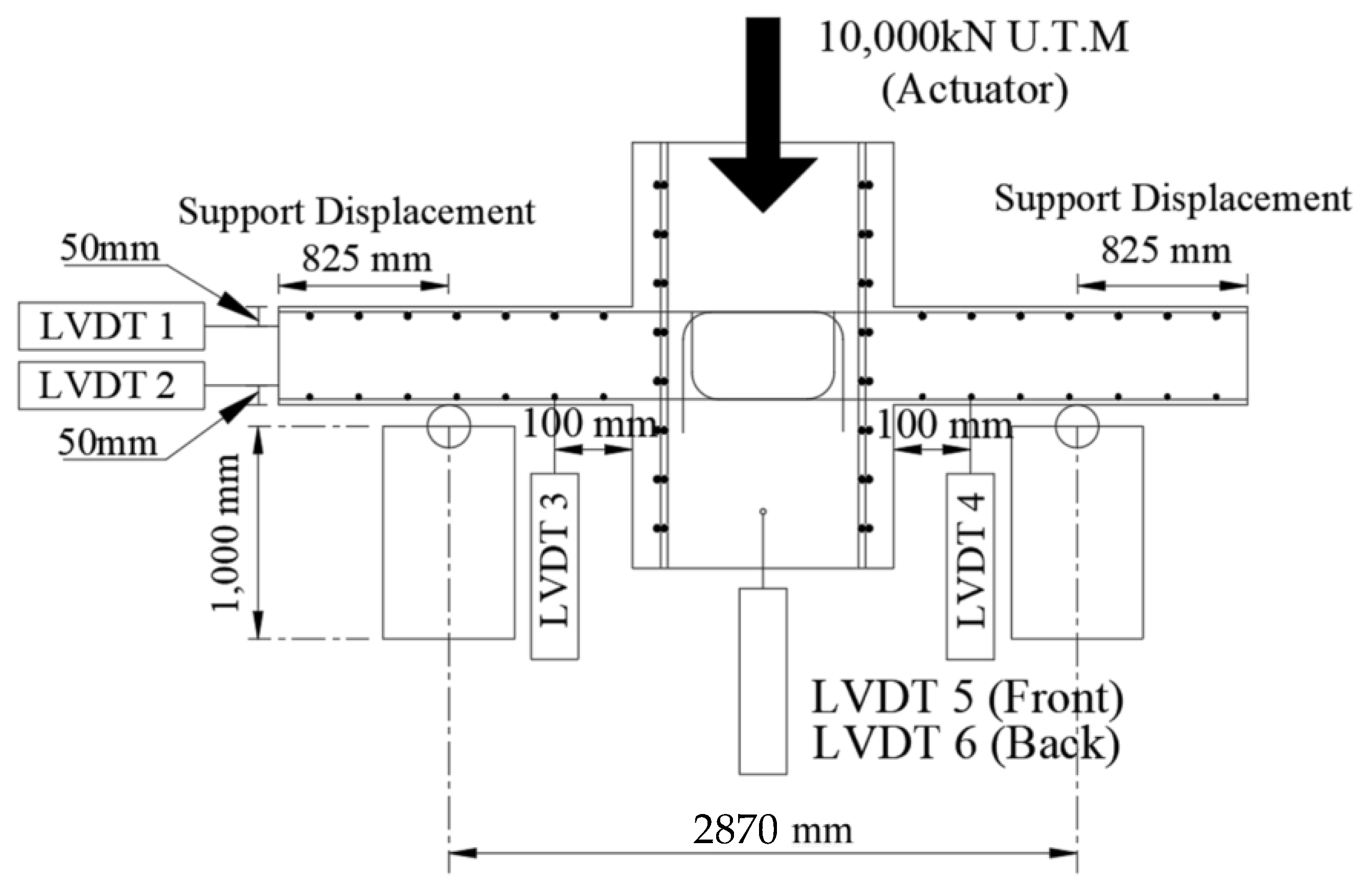
| Specimen | Load (kN, P) | Displacement (mm, δ) | ||
|---|---|---|---|---|
| NS | 1,779.62 | 1.00 | 18.11 | |
| OS | OS-1H | 1757.56 | 0.99 | 12.40 |
| OS-2H | 1926.21 | 1.08 | 13.65 | |
| OS-3H | 856.83 | 0.48 | 10.52 | |
| TS | TS-1H | 1043.66 | 0.59 | 9.99 |
| TS-2H | 901.98 | 0.51 | 15.39 | |
| TS-3H | 856.34 | 0.48 | 14.16 | |
| Specimen | Moment (kN·m) | Angle of Deflection (Radian, θ) | ||||
|---|---|---|---|---|---|---|
| Left (A) | Right (B) | |||||
| NS | 1276.88 | 1.00 | 0.0284 | 0.0245 | 0.00390 | |
| OS | OS-1H | 1261.05 | 0.99 | 0.0159 | 0.0155 | 0.00040 |
| OS-2H | 1382.06 | 1.08 | 0.0201 | 0.0165 | 0.00357 | |
| OS-3H | 614.78 | 0.48 | 0.0189 | 0.0086 | 0.01029 | |
| TS | TS-1H | 748.83 | 0.59 | 0.0043 | 0.0043 | 0 |
| TS-2H | 647.31 | 0.51 | 0.0107 | 0.0104 | 0.00027 | |
| TS-3H | 614.56 | 0.48 | 0.0104 | 0.0089 | 0.00147 | |
| Heating Time (Hours) | Test | EN 1992-1-2 | ACI 216.1M-14, NIST 1681 | Max Difference | ||||||||||
|---|---|---|---|---|---|---|---|---|---|---|---|---|---|---|
| One-Side (OS) | Two-Side (TS) | |||||||||||||
| Load (kN) | Moment (kN·m) | Load (kN) | Moment (kN·m) | Load (kN) | Moment (kN·m) | Load (kN) | Moment (kN·m) | Load (kN) | Moment (kN·m) | |||||
| 0 | 1779 | 1276 | 1779 | 1276 | 1589 | 1140 | 1020 | 719 | 759 | 557 | ||||
| 1 | 1757 | 1261 | 1043 | 748 | 1584 | 1580 | 1137 | 1133 | 1020 | 1001 | 719 | 706 | 756 | 555 |
| 2 | 1926 | 1382 | 901 | 647 | 1584 | 1575 | 1137 | 1130 | 1011 | 992 | 713 | 699 | 1025 | 735 |
| 3 | 856 | 614 | 856 | 614 | 1515 | 1570 | 1087 | 1127 | 865 | 982 | 610 | 692 | 714 | 517 |
Publisher’s Note: MDPI stays neutral with regard to jurisdictional claims in published maps and institutional affiliations. |
© 2021 by the authors. Licensee MDPI, Basel, Switzerland. This article is an open access article distributed under the terms and conditions of the Creative Commons Attribution (CC BY) license (https://creativecommons.org/licenses/by/4.0/).
Share and Cite
Lee, S.-H.; Choi, B.-J. Post Fire Residual Strength of the Wall-Slab Using Siliceous Concrete. Materials 2021, 14, 1793. https://doi.org/10.3390/ma14071793
Lee S-H, Choi B-J. Post Fire Residual Strength of the Wall-Slab Using Siliceous Concrete. Materials. 2021; 14(7):1793. https://doi.org/10.3390/ma14071793
Chicago/Turabian StyleLee, Su-Hyeon, and Byong-Jeong Choi. 2021. "Post Fire Residual Strength of the Wall-Slab Using Siliceous Concrete" Materials 14, no. 7: 1793. https://doi.org/10.3390/ma14071793
APA StyleLee, S.-H., & Choi, B.-J. (2021). Post Fire Residual Strength of the Wall-Slab Using Siliceous Concrete. Materials, 14(7), 1793. https://doi.org/10.3390/ma14071793


