Article

Evaluation of Active Heat Sinks Design under Forced Convection—Effect of Geometric and Boundary Parameters

by
Eva C. Silva
1,2,*,
Álvaro M. Sampaio
1,2,3 and
António J. Pontes
1,2
1
IPC—Institute of Polymers and Composites, Department of Polymer Engineering, Campus de Azurém, University of Minho, 4800-058 Guimarães, Portugal
2
DONE Lab—Advanced Manufacturing of Polymers and Tools, Campus de Azurém, University of Minho, 4800-058 Guimarães, Portugal
3
Lab2PT, School of Architecture, Campus de Azurém, University of Minho, 4800-058 Guimarães, Portugal
*
Author to whom correspondence should be addressed.
Materials 2021, 14(8), 2041; https://doi.org/10.3390/ma14082041
Submission received: 27 February 2021 / Revised: 12 April 2021 / Accepted: 15 April 2021 / Published: 18 April 2021
(This article belongs to the Special Issue Additive Manufacturing Materials and Their Applications)

Abstract

:
This study shows the performance of heat sinks (HS) with different designs under forced convection, varying geometric and boundary parameters, via computational fluid dynamics simulations. Initially, a complete and detailed analysis of the thermal performance of various conventional HS designs was taken. Afterwards, HS designs were modified following some additive manufacturing approaches. The HS performance was compared by measuring their temperatures and pressure drop after 15 s. Smaller diameters/thicknesses and larger fins/pins spacing provided better results. For fins HS, the use of radial fins, with an inverted trapezoidal shape and with larger holes was advantageous. Regarding pins HS, the best option contemplated circular pins in combination with frontal holes in their structure. Additionally, lattice HS, only possible to be produced by additive manufacturing, was also studied. Lower temperatures were obtained with a hexagon unit cell. Lastly, a comparison between the best HS in each category showed a lower thermal resistance for lattice HS. Despite the increase of at least 38% in pressure drop, a consequence of its frontal area, the temperature was 26% and 56% lower when compared to conventional pins and fins HS, respectively, and 9% and 28% lower when compared to the best pins and best fins of this study.

1. Introduction

All electronic devices dissipate heat during their operation. By providing heat dissipation, a heat sink prevents overheating and plays an imperative role in temperature regulation. Through extended surfaces, heat sinks increase heat dissipation from a heat source to the surroundings, providing low thermal resistance (Equation (1)) and a low-pressure loss path between them [1]. They can be divided into two main categories: active and passive cooling techniques. The use of natural techniques is known as passive thermal management while forced heat dissipation, e.g., by cooling fans, improving heat transfer, is referred to as active thermal management [2,3,4,5]. The main advantages of passive cooling techniques are their simplicity and lower cost of operation. However, the associated heat transfer coefficient (h) is low [6]. Forced convection with cooling fans is a process frequently found in a variety of electronic products ranging from personal computers to avionics control systems [7]. Airflow speed is actively increased, enhancing heat transfer [6]. The most typical material for heat sinks is aluminium, offering a good balance between weight, cost, and thermal properties [8,9,10,11].
Nowadays, as electronic components continue to dissipate more heat and, with new developments, are getting more compact, their cooling techniques must also be improved [7]. Due to its geometric freedom and the capability to build complex internal structures and with high total area to volume ratio, additive manufacturing can be a useful way to produce heat sinks that match or outperform the thermal performance of traditional aluminium heat sinks [12]. Chinthavali et al. [13] produced the first heat sink for electronic components by additive manufacturing using powder-bed fusion (PBF) equipment. The toughness of the heat sink produced with the additive manufacturing aluminium alloy was similar to the strength of the heat sink produced by conventional methods, but the thermal performance was lower for lower temperatures. Later, Syed-Khaja et al. [14] used PBF to fabricate a heat sink design that showed key enabling advantages such as the reduction in volume, weight, and chip temperatures. To date, several other studies have emerged regarding heat sinks produced by additive manufacturing [5,15,16,17,18,19,20].
This study aims to evaluate the performance of different heat sinks. In the first stage, the influence of different geometric and boundary parameters on the performance of conventional fins/pins heat sinks will be evaluated. Based on those results, the design of the heat sinks will be changed considering some additive manufacturing approaches and compared with lattice heat sinks, which are complex structures only possible to be produced by additive manufacturing. Finally, the best heat sink design for forced convection environments, among the studied, will be revealed.
Heat sinks performance was evaluated considering their thermal resistance (Equation (1)), which is one of the main indicators and should be as low as possible. It is expressed as:
R = Δ T Q h e a t
where ∆T is the difference between the minimum temperature of the heat sink and the fluid temperature at the inlet and Qheat is the total heat applied at the base of the heat sink, given by multiplying the heat flux by the base area [21,22].
In this work, both the heat source and air flow inlet velocity are constant parameters and were defined at the base of the heat sink and the beginning of the wind tunnel, respectively. The performance of a heat sink design was evaluated by measuring their temperature after 15 s of applied heat and air flow (directly correlated with the thermal resistance according to Equation (3)). Besides the temperature control, the air pressure drop after 15 s was used as an auxiliary control metric to compare studies where the temperature differential was residual or an anormal air pressure was identified.

1.1. Conventional Heat Sinks Design and Topology

Heat sink design is the most important variable for better performance. It minimizes thermal resistance by expanding the surface area available for heat transfer while ensuring that the air flows through the heat sink [3].
Choosing the type of heat sink (pins, fins, or blades) is an ambiguous task. Under forced convection, Wong et al. [23] defended that fins are the best choice (among fins, blades, and circular pins), while Abdelsalam et al. [24] compared in-line blades with fins and concluded that the first was better. In its turn, Jonsson and Moshfegh [25] tested different heat sinks models considering Reynolds numbers in a range between 3350 and 13,400 using ANSYS Fluent software and concluded that it is not favorable to use pin heat sinks at higher Reynolds numbers.
When choosing a fin heat sink, it is typical to choose the conventional rectangular fins. Still, other forms of fins have been tested, such as triangular or trapezoidal fins [26,27], with fillets [28] or holes. Jaffal [29] analysed the thermal performance of different fin heat sinks geometries, via experimental and computational studies, at a certain heat flux interval. It was found that the heat transfer coefficient is dependent on heat flux and that the heat sink with perforated blades showed the best thermal performance. Through simulations in ANSYS software, Ibrahim et al. [30] investigated the effect of perforation geometry (circular, rectangular, and triangular) on the heat transfer of perforated fin heat sinks, under different boundary conditions. In all cases, these perforations increased the heat transfer coefficient and decreased heat sink temperature, regardless of perforation geometry. Tijani and Jaffri [31] also studied the effect of circular perforations on pins or fins heat sinks under forced convection. Inlet velocity and heat flux were constant and perforated pins or fins had the highest heat transfer coefficients, improving thermal efficiency up to 4% compared to solid pins or fins.
When choosing a pin heat sink, several authors agree that square pins are not a good choice [32,33,34] and that pressure drop is higher when pins arrangement is staggered [25,35,36,37]. However, there is no agreement regarding the best pins shape. Under forced convection, either circular [33,38], elliptical [32,39,40,41,42], dropform [43,44], and rhombus [45,46] can be advantageous. Gururatana and Li [40] compared elliptic and rectangular staggered pins with the same length-to-thickness ratio but with different hydraulic diameters. As boundary conditions, an inlet velocity of 6 m/s at 27 °C rendered a Reynolds number of 1192 (laminar flow). Through ANSYS Fluent simulations, they concluded that elliptic fins produced a higher heat transfer rate when the pressure drop is the same. Moreover, Zhou and Catton [39] investigated the thermal and hydraulic performance of different pin heat sinks with distinct pins shapes including square, circular, elliptic, and dropform. The elliptic pins had the best overall performance, regardless of inlet velocity and the ratio of pin widths to pins spacing. There are still other unusual shapes that can be a good choice [47,48]. Maji et al. [47] investigated the thermal performance of heat sinks with perforated circular pins. Results were taken for Reynolds numbers from 4700 to 44,500 and concluded that, up to a certain perforated area, perforated pins required lower pumping power than solid pins to reach the same thermal performance. Perforated pins were also investigated by other authors that also agree on their advantages [49,50].
The greatest fin or pin spacing is dependent on the air velocity, i.e., as the velocity increases, the fin spacing can decrease [3,51]. However, the dependence of heat transfer with fin or pin spacing is not clear. According to some authors [37,39,44], the heat transfer increases with increasing fin or pin density, i.e., with reduced spacing. Contrarily, according to other authors, greater heat transfer is obtained for the opposite [37,52,53].

1.2. Lattice Heat Sinks

As mentioned above, in the field of electronics cooling, where oversized heat sinks are inhibited by volume constraints, the use of additive manufacturing offers the ability to deliver components without the design restrictions of conventional manufacturing methods [48,54]. Lattice structures have showed high potential in increasing forced convection heat transfer. They consist of orderly unit cell arrangements, which can have different configurations such as hexagon, honeycomb, and pyramidal [55]. They have large surface area-to-volume ratios, are light, and promote tortuous fluid paths, promoting fluid mixing. Their advantage over metal foams are constant periodicity and homogeneity allowing optimization of the ligament configuration and diameter, better mechanical properties, and greater ease of production with emerging additive manufacturing technologies [54,55,56]. The study of the fluid flow through them has become popular in thermal management [55,56,57,58,59].
Although the lattice structure heat sink allows a high surface area to volume ratios, its performance may be limited by the absense of interaction between the cooling air and structure [7]. According to Ho et al. [55], pressure drop and Nusselt number of Rhombi-Octet lattice structures increased with decreasing unit cell size and the highest Nusselt number was obtained with the lattice structure with the smallest ligament width. The same conclusion was obtained by Son et al. [60].
Regarding the best unit cell topology for thermal management, there is no clear conclusion. For example, according to Yan et al. [61], the X-type lattice heat sink provides overall heat removal capacity up to two times higher than tetrahedral or the Kagome lattice heat sink. Its morphology resulted in a large scale spiral main flow that interacts with several secondary flows, causing three times higher pressure drop for a given Reynolds number. Still, superior heat transfer was achieved by the X-type lattice. The same conclusion was not made by Hyun and Torquato [62]. They suggested that Kagome structures have desirable heat-dissipation properties due to the large hexagonal holes through which fluid may flow, compared to triangular and hexagonal cells. More recently, Dixit et al. [63] concluded that octet topology dissipates more heat at the lowest Reynolds numbers while SC-BCC-truss outperforms other architectures as the fluid velocity increases.

2. Problem Description

2.1. CFD Methodology

As in other studies involving heat sinks, the main goal is to reach heat sink temperatures as low as possible, minimizing thermal resistance. The computational domain (Figure 1) includes a heat sink (main dimensions 50 × 50 × 50 mm3) and a wind tunnel, designed so that the total flow converges to the heat sink, avoiding the bypass phenomenon [25,55]. It was considered a fan diameter of 80 mm. The dimensions of the domain are a length of 300 mm and a converging width and height from 80 mm to 52 mm. Heat sink is placed inside the domain, 200 mm away from the inlet and 50 mm from the outlet.
The geometry was meshed using ANSYS Meshing by applying body sizing operation and, depending on the heat sink model under study, were considered tetrahedral or hexahedral elements. Element size varied in a range between 0.4 mm and 1.2 mm and the total number of elements was the one whose results converged, with minimal computational effort, i.e., sufficient to ensure mesh independence of the simulated results.
Mesh geometry (Figure 2) was brought into Fluent, where solver settings were defined. This includes defining material properties, selecting appropriate physical models, prescribing operating and boundary conditions, and providing initial values. Table 1 includes the main properties of the materials adopted for each component: aluminium for the heat sink and ideal air as the fluid passing through the heat sink. The air flow was assumed incompressible with constant properties.
As initial values, the system was considered at a room temperature of 20 °C. The outlet vent condition was used for the outlet boundary and the wind tunnel wall considered adiabatic. The remaining boundary conditions (heat source temperature and inlet air velocity) were established according to each specific case.
During compute solution, the discretised conservation equations (Equations (4)–(6)) are solved iteratively until convergence, i.e., when changes in solution variables from one iteration to the next are negligible (residual response less than 10 × 10−6). As the most widely-used engineering turbulence model for industrial applications, standard Ϗ-Epsilon viscous model (Equations (6) and (7)) was selected. The pressure-velocity coupling was achieved through the SIMPLE scheme [64] and the Least Squares Cell Based gradients were choose as the spatial discretization scheme [65].
Pressure drop across the heat sink and its temperature were reported after 15 s on the respective sensors (Figure 1). The temperature sensor was located where, as general rule, the heat sink temperature was the minimum [66]. Considering a time step size of one second with 10 maximum iterations per time step, the 15 s were found to be a good balance between good results and computational effort (Figure 3) once, in most cases, the temperature reached the steady-state condition.

2.2. CFD Governing Equations

Computational Fluid Dynamics (CFD) consists of predicting fluid flow, heat, and mass transfer and related phenomena by solving numerically a set of governing mathematical equations. CFD analysis complements testing and experimentation by reducing total effort and cost required for experimentation and data acquisition. There are a number of commercial CFD software packages available for application in thermal design. One of them is ANSYS. Based on the finite volume method, ANSYS solvers discretised the domain into a finite set of control volumes in which general conservation equations for mass (Equation (2)), momentum (Equation (3)) and energy (Equation (4)) are solved [67].
· ( ρ u ) = 0
( u · ) ( ρ u ) = P + · ( μ u )
u · ( ρ C p T ) = · ( k T i )
Note that ρ and μ are the fluid density and viscosity and u is the velocity vector. The energy equation for solid regions [68] can be written as:
k s 2 T = 0
These equations are solved with the presumption that radiation heat transfer is negligible.
The standard Ϗ-Epsilon viscous model used in this study is a semi-empirical model based on model transport equations for the turbulence kinetic energy (Ϗ) and its dissipation rate (ε), obtained from the following transport equations:
t ( ρ Ϗ ) + x i ( ρ Ϗ u i ) = x j [ ( μ + μ t σ Ϗ ) Ϗ x j ] + G Ϗ + G b ρ ε Y M + S Ϗ
t ( ρ ε ) + x i ( ρ ε u i ) = x j [ ( μ + μ t σ ε ) ε x j ] + C 1 ε ε k ( G k + C 3 ε G b ) C 2 ε ρ ε 2 k + S ε
In these equations, GϏ represents the generation of turbulence kinetic energy due to the mean velocity gradients, Gb is the generation of turbulence kinetic energy due to buoyancy, YM represents the contribution of the fluctuating dilatation in compressible turbulence to the overall dissipation rate, C1ε, C2ε and C3ε are constants, σϏ and σε are the turbulent Prandtl numbers for Ϗ and ε, respectively. SϏ and Sε are user-defined source terms. The Ϗ-epsilon model assumes that the flow is fully turbulent, and the effects of molecular viscosity are negligible [65,69].

2.3. Heat Sink Models

The statistical design of experiments (DOE) was used to design the sets of experiments run in this work for fins and pins heat sinks, in order to optimize the main geometric parameters (pins/fins diameter/thickness and pins/fins spacing).
As boundary conditions, the temperature of the heat source (at the bottom of the heat sink) varied between 80 °C and 100 °C, with 10 °C intervals, and inlet air velocity took the values 0.7 m/s, 2.1 m/s and 3.5 m/s (at 20 °C), leading to Reynolds numbers from 2500 (laminar-turbulent transition) to 12,500 (very turbulent flow).
For fins heat sinks, DOE analyses were performed using fin thickness, fin spacing, inlet velocity, and heat source temperature as factors and pressure drop and heat sink temperature after 15 s as responses. Each factor was considered with three levels (Table 2) and an L9 matrix was constructed.
For pins heat sinks, the arrangement factor (in-line or staggered) was added to compose an L18 DOE matrix. Level and factors are shown in Table 3.
Based on DOE results, the shape of fins or pins was varied according to some previous studies that showed good results [32,38,39,40,41,42,43,44,45,46,70] considering the same boundary parameters. For fins heat sinks (Figure 4), the same number of fins was considered. For pins heat sinks (Figure 5), the same hydraulic diameter and pin spacing was maintained.
In order to confirm the advantages of additive manufacturing for thermal management components, lattice sinks with X, Hexagon, and Snow Flake (Figure 6) unit cells were studied. Cell size and thickness were fixed as well as boundary conditions.

3. Results and Discussion

3.1. Fins Heat Sinks
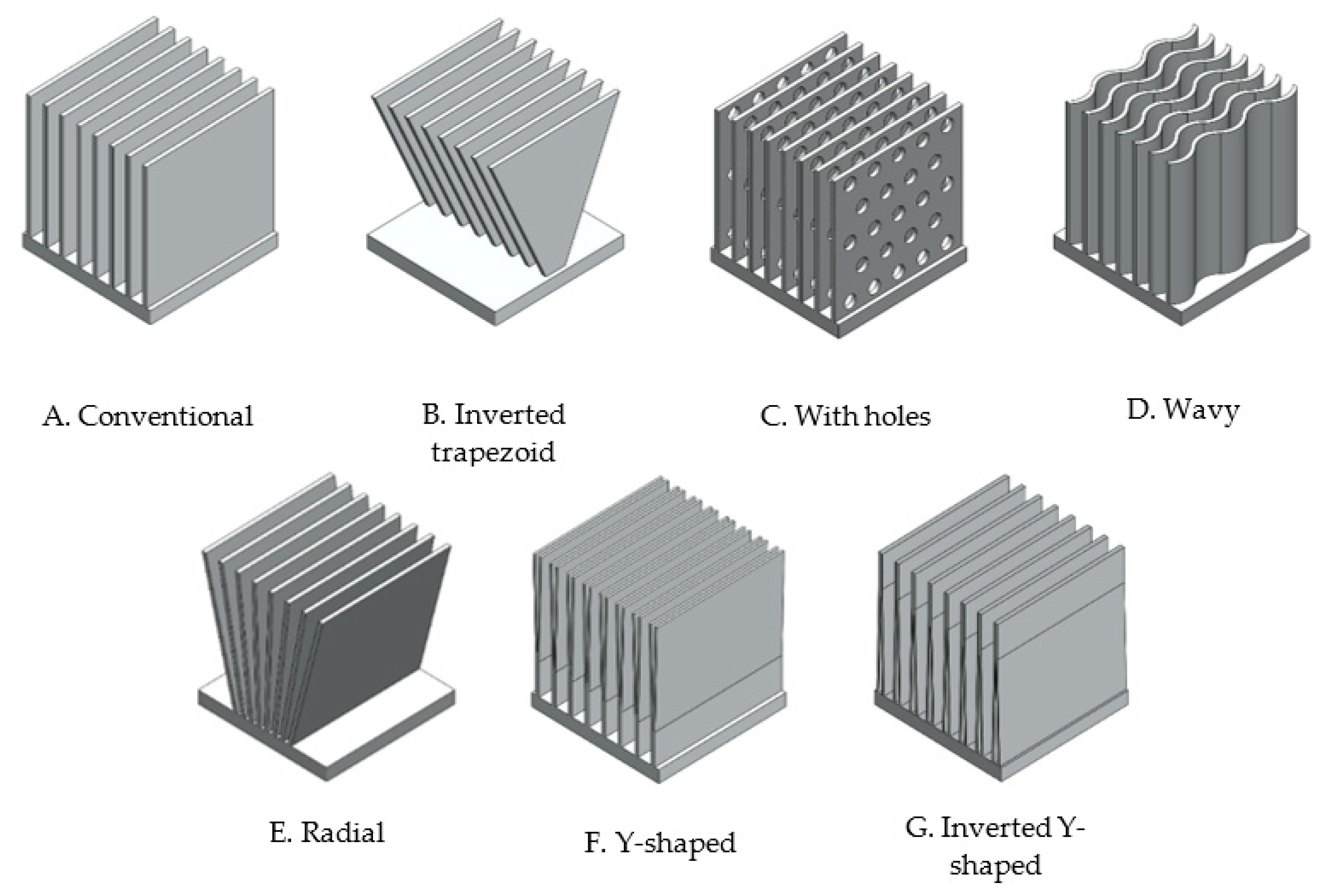
Using analysis of variance (ANOVA), the effects of variables and their interactions on each response were determined. For fins heat sinks, it was found that, either for a lower heat sink temperature (Figure 7, top) or for a lower pressure drop (Figure 7, bottom), the thickness of the fins should be as small as possible. The same was not true for the spacing. On the one hand, if it is as small as possible, it increases the density of the fins and therefore causes better thermal efficiency. On the other hand, the smaller the spacing, the higher pressure drops. In agreement between both parameters, and since the influence is much higher for the pressure drop, the bigger fins spacing (5 mm) was considered for further studies related to the shape of the fins (Figure 4).
Regarding boundary conditions, as expected, the effect of inlet velocity on pressure drop and heat source temperature on heat sink temperature after 15 s was linear. However, an inlet velocity of 2.11 m/s (Re = 7500) caused a minimum heat sink temperature and a heat source temperature of 90 °C caused a minimum pressure drop. These conclusions are related with the geometric parameters (number of fins and fins spacing), according to Table 4 and Table 5, respectively.
As boundary conditions, an inlet velocity of 2.11 m/s and a heat source temperature of 90 °C were considered for further studies with fins.

Fins Shape

In all fins heat sinks variants (Figure 4), the same number of fins (8) and boundary parameters were considered. Results for each model are shown in Table 6.
It was found that the incorporation of fillets or chamfers did not bring any advantage, contrarily to all design variations shown in Figure 4 and Table 6. Fins with trapezoidal and inverted trapezoidal shape (Figure 4B) were considered, the latter being an advantageous option due to its wide part exposed to ambient air [27]. Moreover, the higher the inverted trapezoid angle, the better the performance (Figure 8).
The incorporation of holes in the fins (model C) has been studied by other authors [30,31] and both agreed that it was an advantageous approach due to the higher heat transfer coefficient. Furthermore, for larger holes diameter, maintaining holes spacing (5 mm) resulted in better heat sink performance (Figure 9).
Regarding model E, the lower the spacing between the fins at the bottom, keeping the top spacing equal to 5 mm, the better the heat sink performance (Figure 10, I and II). This happens because airflow towards radial fins tends to quicken as the gap between two consecutive fins reduces (EI to EII) [71]. These advantages of model E fins have also been confirmed experimentally by other authors [71,72]. However, the incorporation of more material in the heat sink base (Figure 10, III), close to the fins, did not bring any advantage.
With this, the properties of models B, C, and E have been combined and, among the studied, the heat sink design with the best performance was attained (Figure 11). Following some design rules for additive manufacturing, elliptical holes were considered instead of circular ones.

3.2. Pins Heat Sinks

For pins heat sinks, the arrangement factor was added: in-line or staggered pins (Figure 12). For staggered pins, there are two possible orientations (1 and 2). From orientation 1 to orientation 2, heat sink temperature increased by a maximum of 1.4% but pressure drop decreased by about 25%. Although the heat sink temperature after 15 s is the most pertinent response parameter, the decrease in pressure drop was much higher, causing a better performance for orientation 2 (Figure 12c). For this reason, the staggered arrangement was considered with orientation 2.
Taking this into account, it was found that, either for a lower heat sink temperature or for a lower pressure drop, the staggered arrangement (2) is more advantageous (Figure 13). Regarding pins diameter, for a lower heat sink temperature (Figure 13, top), it should be as small as possible. The same was not true for the pressure drop (Figure 13, bottom), where there is an ideal diameter of 2.5 mm. In agreement between both parameters, and since the heat sink temperature is the most relevant response parameter and the influence is more accentuated, the lower pins diameter (1.5 mm) will be considered for further studies related to the shape of the pins. With a smaller diameter, there is also a smaller building volume to be created by additive manufacturing.
Respecting pins spacing, if, on the one hand, there was no influence on the heat sink temperature, on the other hand, the influence on the pressure drop is quite noticeable. For this reason, the upper spacing (5 mm) was considered the best choice. These conclusions about geometric parameters are in agreement with the fin heat sinks.
As explained for fins heat sinks, a temperature of 90 °C caused a lower pressure drop (almost irrelevant) also due to some geometrical parameters (pins spacing and heat sink front area) given in Table 7. For this reason, this temperature was selected for further studies with pins. Regarding the inlet velocity, its influence was linear and as expected. Therefore, a velocity of 3.51 m/s was considered because it resulted in a lower heat sink temperature.

Pins Shape

In all pins shapes studies (Figure 5), the same hydraulic diameter (1.5 mm) and pin spacing (5 mm) were maintained, as well as boundary parameters. Results are shown in Table 8.
Conventional heat sinks, with circular pins, continue to be the best choice among the many options of pin shapes, even though the pressure drop is high. For these pins, considering drawing outwards (Figure 14), only possible to be produced by additive manufacturing, was not advantageous—a higher temperature and a higher-pressure drop was obtained.
Figure 15 shows pins heat sinks with 1 mm frontal elliptical holes (H2) and side elliptical holes (H3) as well as a radial pins heat sink also with frontal elliptical holes (H4), spaced 5 mm apart. In all cases, holes were advantageous and the results were quite similar. For the same heat sink temperature obtained, the one with the lowest pressure drop was considered as the best option for pins heat sinks (H2).
For the case of ellipse pins (the second-best pins shape), differences were observed between maintaining the spacing (Model I) or maintaining the number of pins (Model I1), concerning the reference heat sink (Model H). According to Table 9, there were no significant differences, i.e., opting for ellipse pins, the choice should be Model I once it has a smaller building volume.
Therefore, the best option contemplated circular pins in combination with frontal holes in their structure (Figure 16).

3.3. Lattice Heat Sinks

Lattice sinks with X, Hexagon, and Snow Flake (Figure 6) unit cells were studied. Cell size and thickness were fixed at 15 × 15 × 15 mm3 and 1.5 mm, respectively, as well as boundary conditions (heat source temperature of 90 °C and air inlet velocity of 3.5 m/s). The results are shown in Table 10.
Among the three models studied, the heat sink with hexagon unit cell showed the lowest temperature, despite the higher pressure drop. This heat sink has the middle total area to volume ratio. The advantages of this unit cell in thermal management applications were also confirmed by Gu et al. [73].

3.4. Fins vs. Pins vs. Lattice Heat Sink

In this subchapter, it is intended to directly compare the best fins, pins, and blades heat sinks (Figure 17), under the same geometric and boundary parameters.
Table 11 shows that, under forced convection environments, better results were obtained for the lattice heat sink with hexagon unit cell. The pressure drop increased more than double for the same inlet velocity and Reynolds number, a consequence of the high frontal area. Even so, a decrease of about 28% and 9% in heat sink temperature was achieve, comparing with the best fins and pins heat sink, respectively. As inlet velocity and heat source temperature are kept constant during the experiments, the best heat sink is the one whose temperature is minimal, which, according to Equation (3), translates into lower thermal resistance.
Based on this study, there is a direct correlation between the total area to volume ratio and the heat sink performance. The lattice heat sink, the heat sink with the highest area to volume ratio and only possible to be produced by additive manufacturing, was considered the best option among the studied.

4. Conclusions

The thermal performance of heat sinks design under forced convection, varying geometric and boundary parameters (inlet velocity and heat source temperature), was conducted by computational fluid dynamics simulation with ANSYS Fluent.
Considering heat sinks with fins configuration, it was found out that the thickness of the fins should be as thin as possible and widely spaced. The optimal design is obtained by an agreement between both parameters. However, since the spacing has a greater impact on the pressure drop, the bigger fins spacing (5 mm) was considered for studies related to the shape of the fins. For this last iteration on the shape configuration, all geometric and boundary parameters were kept constant, varying only in heat sinks design. It was found that radial fins designed with an inverted trapezoidal shape and with holes have great advantages and the design (Figure 11) was the one with better performance.
A similar study was done for pins heat sinks. It was found that the best solution would be to consider a pin diameter of 1.5 mm with a spacing of 5 mm and with a staggered arrangement. By varying the shape of the pins, it was also found that the incorporation of holes in circular pins was beneficial for thermal performance.
Taking advantage of additive manufacturing freedom of design, three different lattice structures with the same cell size (15 × 15 × 15mm3) and thickness of 1.5 mm but different cell topology were compared. Among X, Hexagon, and Snow Flake unit cells, it was found that the Hexagon unit cell exhibited the best performance.
Through a direct comparison of the thermal efficiency of three heat sinks (the best fins, pins and lattice heat sinks), under the same boundary conditions, it was concluded that, under forced convection environments, a lattice heat sink with a hexagon unit cell is the optimal choice. These results validated how advantageous additive manufacturing can be for components that require thermal management, such as electronic devices. Even so, more studies should be treated to reduce pressure drop and optimize the lattice heat sink in terms of cell size and thickness.

Author Contributions

Conceptualization, methodology, software, formal analysis, investigation, resources, writing—original draft preparation, E.C.S.; writing—review and editing, supervision, Á.M.S. and A.J.P. All authors have read and agreed to the published version of the manuscript.

Funding

This research was funded by Portuguese Fundação para a Ciência e a Tecnologia (FCT), for financial support under the PhD scholarship SFRH/BD/144590/2019 and by European Structural and Investment Funds in the FEDER component, through the Operational Competitiveness and Internationalization Programme (COMPETE 2020) [Project No. 039334; Funding Reference: POCI-01-0247-FEDER-039334].

Institutional Review Board Statement

Not applicable.

Informed Consent Statement

Not applicable.

Data Availability Statement

Not applicable.

Conflicts of Interest

The authors declare no conflict of interest.

Nomenclature

qHeat Flux Density (W·m2)
ρair density (kg·m−e)
T n thermal gradient in direction n (K·m−1)
ttime (s)
Aheat transfer area (m2)
u velocity vector (m/s)
Pair pressure (Pa)
Rthermal resistance (K·W−1)
Tffluid temperature (K)
μair viscosity (kg·m−1·s−1)
CpSpecific Heat Capacity (J·kg−1·K−1)
Ϗturbulence kinetic energy (J·kg)
Tdifference between the minimum temperature of the HS and the fluid temperature at the inlet (K)
Qheattotal heat applied at the base of the HS (W)
hconvective heat transfer coefficient (W·m−2·K−1)
kthermal conductivity (W·m−1·K−1)
TsHS surface temperature (K)
Tiinlet air temperature (K)
σϏturbulent Prandtl number for Ϗ
σεturbulent Prandtl numbers for ε
Acronyms
CFDComputational Fluid Dynamics
DOEDesign of experiments
HSHeat sink

References

  1. Dede, E.M.; Joshi, S.N.; Zhou, F. Topology Optimization, Additive Layer Manufacturing, and Experimental Testing of an Air-Cooled Heat Sink. J. Mech. Des. Trans. ASME 2015, 137, 11. [Google Scholar] [CrossRef]
  2. Brindley, K. Newnes Electronics Assembly Handbook, 1st ed.; Heinemann Newnes: Manchester, UK, 1990; ISBN 0 434 90203 9. [Google Scholar]
  3. Fowler, K.R.; Silver, C.L. Developing and Managing Embedded Systems and Products: Methods, Techniques, Tools, Processes, and Teamwork, 1st ed.; Fowler, K., Ed.; Newnes: Boston, MA, USA, 2014; ISBN 9780124058637. [Google Scholar]
  4. Wilson, P. The Circuit Designer’s Companion, 4th ed.; Elsevier Ltd.: London, UK, 2017; ISBN 9780081017647. [Google Scholar]
  5. Otake, S.; Tateishi, Y.; Gohara, H.; Kato, R.; Ikeda, Y.; Parque, V.; Faiz, M.K.; Yoshida, M.; Miyashita, T. Heatsink design using spiral-fins considering additive manufacturing. In Proceedings of the 2019 International Conference on Electronics Packaging (ICEP), Niigata, Japan, 17–20 April 2019; Volume 175, pp. 46–51. [Google Scholar]
  6. Bergman, T.L.; Lavine, A.S.; Incropera, F.P.; Dewitt, D.P. Introduction to Heat Transfer, 6th ed.; Don Fowley: Hoboken, NJ, USA, 2011; ISBN 9788578110796. [Google Scholar]
  7. Wong, M.; Owen, I.; Sutcliffe, C.J.; Puri, A. Convective heat transfer and pressure losses across novel heat sinks fabricated by Selective Laser Melting. Int. J. Heat Mass Transf. 2009, 52, 281–288. [Google Scholar] [CrossRef]
  8. Mohamad Nor, N.H.; Ismail, M.H.; Abu Kasim, N.A.; Teng, W.D.; Idris, M.I.I. Magnesite effect to the alumina sintering for heat sink application. Appl. Mech. Mater. 2014, 465–466, 70–75. [Google Scholar]
  9. Seo, J.H.; Lee, M.Y. Illuminance and heat transfer characteristics of high power LED cooling system with heat sink filled with ferrofluid. Appl. Therm. Eng. 2018, 143, 438–449. [Google Scholar] [CrossRef]
  10. Baldry, M.; Timchenko, V.; Menictas, C. Optimal design of a natural convection heat sink for small thermoelectric cooling modules. Appl. Therm. Eng. 2019, 160, 114062. [Google Scholar] [CrossRef]
  11. Martínez-Maradiaga, D.; Damonte, A.; Manzo, A.; Haertel, J.H.K.; Engelbrecht, K. Design and testing of topology optimized heat sinks for a tablet. Int. J. Heat Mass Transf. 2019, 142, 118429. [Google Scholar] [CrossRef]
  12. Chinthavali, M.S.; Wang, Z.J. 30-kW All-SiC inverter with 3D-printed air-cooled heatsinks for plug-in and full electric vehicle applications. Mater. Sci. Forum 2018, 924, 845–848. [Google Scholar] [CrossRef]
  13. Chinthavali, M.; Ayers, C.; Campbell, S.; Wiles, R.; Ozpineci, B. A 10-kW SiC inverter with a novel printed metal power module with integrated cooling using additive manufacturing. In Proceedings of the 2014 IEEE Workshop on Wide Bandgap Power Devices and Applications, Knoxville, TN, USA, 13–15 October 2014; pp. 48–54. [Google Scholar] [CrossRef]
  14. Syed-Khaja, A.; Freire, A.P.; Kaestle, C.; Franke, J. Feasibility Investigations on Selective Laser Melting for the Development of Microchannel Cooling in Power Electronics. Proc. Electron. Compon. Technol. Conf. 2017, 1491–1496. [Google Scholar] [CrossRef]
  15. Collins, I.L.; Weibel, J.A.; Pan, L.; Garimella, S.V. A permeable-membrane microchannel heat sink made by additive manufacturing. Int. J. Heat Mass Transf. 2019, 131, 1174–1183. [Google Scholar] [CrossRef] [Green Version]
  16. Catchpole-Smith, S.; Sélo, R.R.J.; Davis, A.W.; Ashcroft, I.A.; Tuck, C.J.; Clare, A. Thermal Conductivity of TPMS Lattice Structures Manufactured via Laser Powder Bed Fusion. Addit. Manuf. 2019, 30, 1–9. [Google Scholar] [CrossRef]
  17. Vaissier, B.; Pernot, J.P.; Chougrani, L.; Véron, P. Parametric design of graded truss lattice structures for enhanced thermal dissipation. CAD Comput. Aided Des. 2019, 115, 1–12. [Google Scholar] [CrossRef]
  18. Han, Y.; Lu, W.F. A novel design method for nonuniform lattice structures based on topology optimization. J. Mech. Des. Trans. ASME 2018, 140, 1–10. [Google Scholar] [CrossRef]
  19. Lazarov, B.S.; Sigmund, O.; Meyer, K.E.; Alexandersen, J. Experimental validation of additively manufactured optimized shapes for passive cooling. Appl. Energy 2018, 226, 330–339. [Google Scholar] [CrossRef] [Green Version]
  20. Santhanakrishnan, M.S.; Tilford, T.; Bailey, C. Multi-Material Heatsink Design Using Level-Set Topology Optimization. IEEE Trans. Compon. Packag. Manuf. Technol. 2019, 9, 1504–1513. [Google Scholar] [CrossRef]
  21. Ansari, D.; Kim, K.Y. Hotspot management using a hybrid heat sink with stepped pin-fins. Numer. Heat Transf. Part A Appl. 2019, 75, 359–380. [Google Scholar] [CrossRef]
  22. Wits, W.W.; Jafari, D.; Jeggels, Y.; Van De Velde, S.; Jeggels, D.; Engelberts, N. Freeform-Optimized Shapes for Natural-Convection Cooling. Mater. Sci. 2018, 2018, 1–6. [Google Scholar]
  23. Wong, C.M.; Aziz, M.H.B.A.; Ong, N.R.; Alcain, J.B.; Sauli, Z. Variation in heat sink shape for thermal analysis. AIP Conf. Proc. 2017, 1885. [Google Scholar] [CrossRef]
  24. Abdelsalam, Y.O.; Alimohammadi, S.; Pelletier, Q.; Persoons, T. A multi-objective genetic algorithm optimisation of plate-fin heatsinks. In Proceedings of the 2017 23rd International Workshop on Thermal Investigations of ICs and Systems (THERMINIC), Amsterdam, The Netherlands, 27–29 September 201; pp. 1–6.
  25. Jonsson, H.; Moshfegh, B. Modeling of the Thermal and Hydraulic Performance of Plate Fin, Strip Fin, and Pin Fin Heat Sinks—Influence of Flow Bypass. IEEE Exp. 2001, 24, 142–149. [Google Scholar] [CrossRef]
  26. Kim, D.K. Thermal optimization of plate-fin heat sinks with fins of variable thickness under natural convection. Int. J. Heat Mass Transf. 2012, 55, 752–761. [Google Scholar] [CrossRef]
  27. Charles, R.; Wang, C.C. An optimized heat dissipation fin design applicable for natural convection augmentation (IMPACT 2014). In Proceedings of the 2014 9th International Microsystems, Packaging, Assembly and Circuits Technology Conference (IMPACT), Taipei, Taiwan,, 22–24 October 2014; pp. 61–64. [Google Scholar]
  28. Wong, K.C.; Indran, S. Impingement heat transfer of a plate fin heat sink with fillet profile. Int. J. Heat Mass Transf. 2013, 65, 1–9. [Google Scholar] [CrossRef]
  29. Jaffal, H.M. The Effect of Fin Design on Thermal Performance of Heat Sink. Univ. Baghdad Eng. J. 2017, 23, 123–146. [Google Scholar]
  30. Ibrahim, T.K.; Mohammed, M.N.; Mohammed, M.K.; Najafi, G.; Azwadi Che Sidik, N.; Basrawi, F.; Abdalla, A.N.; Hoseini, S.S. Experimental study on the effect of perforations shapes on vertical heated fins performance under forced convection heat transfer. Int. J. Heat Mass Transf. 2018, 118, 832–846. [Google Scholar] [CrossRef] [Green Version]
  31. Tijani, A.S.; Jaffri, N.B. Thermal analysis of perforated pin-fins heat sink under forced convection condition. Procedia Manuf. 2018, 24, 290–298. [Google Scholar] [CrossRef]
  32. Khan, W.A.; Culham, J.R.; Yovanovich, M.M. The role of fin geometry in heat sink performance. J. Electron. Packag. Trans. ASME 2006, 128, 324–330. [Google Scholar] [CrossRef]
  33. Kou, H.S.; Lee, J.J.; Lai, C.Y. Thermal analysis and optimum fin length of a heat sink. Heat Transf. Eng. 2003, 24, 18–29. [Google Scholar] [CrossRef]
  34. Kou, H.S.; Lee, J.J.; Chen, C.W. Optimum thermal analysis of a heat sink with various fin cross-sections by adjusting fin length and cross-section. Heat Transf. Eng. 2008, 29, 537–545. [Google Scholar] [CrossRef]
  35. Khan, W.A.; Culham, J.R.; Yovanovich, M.M. Modeling of cylindrical pin-fin heat sinks for electronic packaging. Annu. IEEE Semicond. Therm. Meas. Manag. Symp. 2005, 31, 125–134. [Google Scholar]
  36. Khan, W.A.; Culham, J.R.; Yovanovich, M.M. Optimization of pin-fin heat sinks in bypass flow using entropy generation minimization method. J. Electron. Packag. Trans. ASME 2008, 130, 0310101–0310107. [Google Scholar] [CrossRef]
  37. Zografos, A.I.; Sunderland, J.E. Numerical simulation of natural convection from pin fin arrays. Am. Soc. Mech. Eng. Heat Transf. Div. HTD 1990, 157, 55–61. [Google Scholar]
  38. Zhou, F.; Catton, I. Numerical evaluation of flow and heat transfer in plate-pin fin heat sinks with various pin cross-sections. Numer. Heat Transf. Part A Appl. 2011, 60, 107–128. [Google Scholar] [CrossRef] [Green Version]
  39. Sahiti, N.; Durst, F.; Geremia, P. Selection and optimization of pin cross-sections for electronics cooling. Appl. Therm. Eng. 2007, 27, 111–119. [Google Scholar] [CrossRef]
  40. Gururatana, S.; Li, X. Numerical simulation of heat sink performance with interrupted and staggered fins. In Proceedings of the ASME 2009 Heat Transfer Summer Conference collocated with the InterPACK09 and 3rd Energy Sustainability Conferences, San Francisco, CA, USA, 19–23 July 2009; Volume 1, pp. 989–996. [Google Scholar]
  41. Abdel-Rehim, Z.S. Optimization and thermal performance assessment of pin-fin heat sinks. Energy Sources Part A Recover. Util. Environ. Eff. 2009, 31, 51–65. [Google Scholar] [CrossRef]
  42. Yang, K.S.; Chu, W.H.; Chen, I.Y.; Wang, C.C. A comparative study of the airside performance of heat sinks having pin fin configurations. Int. J. Heat Mass Transf. 2007, 50, 4661–4667. [Google Scholar] [CrossRef]
  43. Ho, J.Y.; Wong, K.K.; Leong, K.C.; Wong, T.N. Convective heat transfer performance of airfoil heat sinks fabricated by selective laser melting. Int. J. Therm. Sci. 2017, 114, 213–228. [Google Scholar] [CrossRef]
  44. Khazaka, R.; Martineau, D.; Youssef, T.; Le, T.L.; Azzopardi, S. Direct Printing of Heat Sinks, Cases and Power Connectors on Insulated Substrate Using Selective Laser Melting Techniques. In Proceedings of the 2019 IEEE 69th Electronic Components and Technology Conference (ECTC), Las Vegas, NV, USA, 28–31 May 2019; pp. 2173–2179. [Google Scholar]
  45. Xia, G.; Chen, Z.; Cheng, L.; Ma, D.; Zhai, Y.; Yang, Y. Micro-PIV visualization and numerical simulation of flow and heat transfer in three micro pin-fin heat sinks. Int. J. Therm. Sci. 2017, 119, 9–23. [Google Scholar] [CrossRef]
  46. Wong, M.; Tsopanos, S.; Sutcliffe, C.J.; Owen, I. Selective laser melting of heat transfer devices. Rapid Prototyp. J. 2007, 13, 291–297. [Google Scholar] [CrossRef]
  47. Maji, A.; Bhanja, D.; Patowari, P.K. Effect of knurled fin surface on thermal performance of perforated fin heat sink. J. Thermophys. Heat Transf. 2019, 33, 580–598. [Google Scholar] [CrossRef]
  48. Ramphueiphad, S.; Bureerat, S. Synthesis of multiple cross-section pin fin heat sinks using multiobjective evolutionary algorithms. Int. J. Heat Mass Transf. 2018, 118, 462–470. [Google Scholar] [CrossRef]
  49. Gupta, D.; Saha, P.; Roy, S. Computational analysis of perforation effect on the thermo-hydraulic performance of micro pin-fin heat sink. Int. J. Therm. Sci. 2021, 163, 106857. [Google Scholar] [CrossRef]
  50. Sahel, D.; Bellahcene, L.; Yousfi, A.; Subasi, A. Numerical investigation and optimization of a heat sink having hemispherical pin fins. Int. Commun. Heat Mass Transf. 2021, 122, 105133. [Google Scholar] [CrossRef]
  51. Peles, Y.; Koşar, A.; Mishra, C.; Kuo, C.J.; Schneider, B. Forced convective heat transfer across a pin fin micro heat sink. Int. J. Heat Mass Transf. 2005, 48, 3615–3627. [Google Scholar] [CrossRef]
  52. Hatakeyama, T.; Ishizuka, M.; Kibushi, R. Experimental study on the performance of compact heat sink for LSI packages. In Proceedings of the 2012 7th International Microsystems, Packaging, Assembly and Circuits Technology Conference (IMPACT), Taipei, Taiwan, 24–26 October 2012; Volume 7, pp. 193–196. [Google Scholar]
  53. Gao, L.; Sun, S.; Zhao, Y.; Sun, Y. Thermostructural multiobjective optimization of a composite sandwich panel with lattice truss cores. Numer. Heat Transf. Part B Fundam. 2016, 70, 233–250. [Google Scholar] [CrossRef]
  54. Roper, C.S. Multiobjective optimization for design of multifunctional sandwich panel heat pipes with micro-architected truss cores. Int. J. Heat Fluid Flow 2011, 32, 239–248. [Google Scholar] [CrossRef]
  55. Ho, J.Y.; Leong, K.C.; Wong, T.N. Experimental and numerical investigation of forced convection heat transfer in porous lattice structures produced by selective laser melting. Int. J. Therm. Sci. 2019, 137, 276–287. [Google Scholar] [CrossRef]
  56. Bhattacharya, A.; Mahajan, R.L. Finned metal foam heat sinks for electronics cooling in forced convection. J. Electron. Packag. Trans. ASME 2002, 124, 155–163. [Google Scholar] [CrossRef]
  57. Billiet, M.; De Schampheleire, S.; Huisseune, H.; De Paepe, M. Influence of orientation and radiative heat transfer on aluminum foams in buoyancy-induced convection. Materials 2015, 8, 6792–6805. [Google Scholar] [CrossRef] [Green Version]
  58. Maloney, K.J.; Fink, K.D.; Schaedler, T.A.; Kolodziejska, J.A.; Jacobsen, A.J.; Roper, C.S. Multifunctional heat exchangers derived from three-dimensional micro-lattice structures. Int. J. Heat Mass Transf. 2012, 55, 2486–2493. [Google Scholar] [CrossRef]
  59. Cormier, Y.; Dupuis, P.; Jodoin, B.; Corbeil, A. Net shape fins for compact heat exchanger produced by cold spray. J. Therm. Spray Technol. 2013, 22, 1210–1221. [Google Scholar] [CrossRef]
  60. Son, K.N.; Weibel, J.A.; Kumaresan, V.; Garimella, S.V. Design of multifunctional lattice-frame materials for compact heat exchangers. Int. J. Heat Mass Transf. 2017, 115, 619–629. [Google Scholar] [CrossRef] [Green Version]
  61. Yan, H.B.; Zhang, Q.C.; Lu, T.J.; Kim, T. A lightweight X-type metallic lattice in single-phase forced convection. Int. J. Heat Mass Transf. 2015, 83, 273–283. [Google Scholar] [CrossRef]
  62. Hyun, S.; Torquato, S. Optimal and manufacturable two-dimensional, Kagomé-like cellular solids. J. Mater. Res. 2002, 17, 137–144. [Google Scholar] [CrossRef] [Green Version]
  63. Dixit, T.; Nithiarasu, P.; Kumar, S. Numerical evaluation of additively manufactured lattice architectures for heat sink applications. Int. J. Therm. Sci. 2021, 159, 106607. [Google Scholar] [CrossRef]
  64. Patankar, S.V. Calculation of the flow field. In Numerical Heat Transfer and Fluid Flow; Phillips, M.A., Millman, E.M., Eds.; Hemisphere Publishing Corporation: New York, NY, USA, 1980; pp. 113–138. ISBN 0-89116-522-3. [Google Scholar]
  65. Moukalled, F.; Mangani, L.; Darwish, M. The Finite Volume Method in Computational Fluid Dynamics; Thess, A., Moreau, R., Eds.; Springer: Cham, Switzerland, 2016; Volume 113, ISBN 9783319168739. [Google Scholar]
  66. Wu, T.; Ozpineci, B.; Ayers, C. Genetic algorithm design of a 3D printed heat sink. In Proceedings of the 2016 IEEE Applied Power Electronics Conference and Exposition (APEC), Long Beach, CA, USA, 20–24 March 2016; pp. 3529–3536. [Google Scholar]
  67. Tong, X.C. Thermal Management Fundamentals and Design Guides in Electronic Packaging. In Advanced Materials for Thermal Management of Electronic Packaging; Itoh, K., Lee, T., Sakurai, T., Sansen, W.M.C., Schmitt-Landsiedel, D., Eds.; Springer: New York, NY, USA, 2011; pp. 1–58. ISBN 9788578110796. [Google Scholar]
  68. Adewumi, O.O.; Bello-Ochende, T.; Meyer, J.P. Numerical Investigation into the Thermal Performance of Single Microchannels with Varying Axial Length and Different Shapes of Micro Pin-Fin Inserts. Heat Transf. Eng. 2017, 38, 1157–1170. [Google Scholar] [CrossRef]
  69. Launder, B.E.; Spalding, D.B. Lectures in Mathematical Models of Turbulence; Academic Press: London, UK, 1979; ISBN1 0124380506. ISBN2 9780124380509. [Google Scholar]
  70. John, T.J.; Mathew, B.; Hegab, H. Parametric study on the combined thermal and hydraulic performance of single phase micro pin-fin heat sinks part I: Square and circle geometries. Int. J. Therm. Sci. 2010, 49, 2177–2190. [Google Scholar] [CrossRef]
  71. Lin, S.C.; Chuang, F.S.; Chou, C.A. Experimental study of the heat sink assembly with oblique straight fins. Exp. Therm. Fluid Sci. 2005, 29, 591–600. [Google Scholar] [CrossRef]
  72. Tavassoli, B. Novel Heat Sink Design for Low Speed. Math. Problem Eng. 2000, 8, 16–20. [Google Scholar]
  73. Gu, S.; Lu, T.J.; Evans, A.G. On the design of two-dimensional cellular metals for combined heat dissipation and structural load capacity. Int. J. Heat Mass Transf. 2001, 44, 2163–2175. [Google Scholar] [CrossRef]
Figure 1. Computational domain.
Materials 14 02041 g001
Figure 2. Lattice heat sink mesh.
Materials 14 02041 g002
Figure 3. Temperature contours vs. time for each type of heat sink.
Materials 14 02041 g003
Figure 4. Different fins heat sink models.
Materials 14 02041 g004
Figure 5. Different pins shapes under study.
Materials 14 02041 g005
Figure 6. Different lattice heat sinks models.
Materials 14 02041 g006
Figure 7. Main effects for heat sink temperature (top) and pressure drop (bottom) for fins heat sinks.
Materials 14 02041 g007aMaterials 14 02041 g007b
Figure 8. Model B variants.
Materials 14 02041 g008
Figure 9. Model C variants.
Materials 14 02041 g009
Figure 10. Model E variants.
Materials 14 02041 g010
Figure 11. Best fin heat sink (among those studied).
Materials 14 02041 g011
Figure 12. Results for the possible pin heat sinks arrangements and orientations.
Materials 14 02041 g012
Figure 13. Main effects for heat sink temperature (top) and pressure drop (bottom) for pins heat sinks.
Materials 14 02041 g013
Figure 14. Comparison between circular pins (A) and circular pins outwards (A1).
Materials 14 02041 g014
Figure 15. Pins heat sinks with frontal (H2) and side (H3) holes and radial pins heat sink with frontal holes (H4).
Materials 14 02041 g015
Figure 16. Best pin heat sink (among those studied).
Materials 14 02041 g016
Figure 17. Fins, pins, and lattice heat sinks, respectively.
Materials 14 02041 g017
Table 1. Main properties of the materials considered for each component.
PropertyAluminium
(Heat Sink)
Air
(Fluid Domain)
Density (kg·m3)27191.225
Specific heat (J·kg−1·°C−1)8711006.43
Thermal conductivity (W·m−1·°C−1)202.40.0242
Viscosity (kg·m−1·s−1)-1.7894 × 10⁻⁵
Table 2. Levels and factors for DOE matrix for fins heat sinks.
LevelFin Thickness (mm)Fin Spacing (mm)Inlet Velocity (m/s)Heat Source Temperature (°C)
11.52.00.780
22.53.52.190
33.55.03.5100
Table 3. Levels and factors for DOE matrix for pins heat sinks.
LevelPin Diameter (mm)Pins Spacing (mm)Inlet Velocity(m/s)Heat Source Temperature (°C)Arrangement
11.52.00.780In-line (1)
22.53.52.190Staggered (2)
33.55.03.5100-
Table 4. Correlation between heat sink temperature and geometrical parameters.
SimulationNumber of FinsHeat Source Temperature (°C)Velocity (m/s)HS Temperature after 15 s (°C)
#114800.752.2
#26802.1156.4
#38803.5154.1
#47900.761.9
#511902.1157.7
#68903.5160.5
#771000.768.6
#8101002.1163.5
#991003.5165.3
Table 5. Correlation between pressure drop and DOE factors.
SimulationSpacing (mm)Heat Source Temperature (°C)Velocity (m/s)Pressure Drop (Pa)
#12800.713.8
#23.5900.710.5
#351000.74.4
#45802.1140.3
#52902.11108.4
#63.51002.1122.3
#73.5803.51105.1
#85903.5132.6
#921003.51380.1
Table 6. Temperature and pressure drop for each fin heat sink model.
ModelTotal Area
(cm2)
Front Area
(cm2)
Volume
(cm3)
HS Temperature after 15 sec (°C)Pressure Drop
(Pa)
A408.97.738.660.613.4
B260.77.727.040.030.6
C389.47.734.252.425.1
D397.320.235.153.952.6
E414.57.738.655.222.4
F682.17.738.652.031.5
G682.17.738.654.524.5
Table 7. Correlation between pressure drop and geometrical parameters for an inlet air velocity of 3.51 m/s.
ArrangementSimulationSpacing (mm)Front Area (mm2)Heat Source Temperature (°C)Pressure Drop (Pa)
In line#13.513.480289.7
#2510.290167.1
#3216.6100776.9
Staggered#43.511.480170.7
#557.790116.0
#6211.8100441.1
Table 8. Temperature and pressure drop for each pin heat sink model.
ModelNr of PinsTotal Area (cm2)Front Area (cm2)Volume (cm3)HS Temperature after 15 s (°C)Pressure Drop (Pa)
H60162.77.716.136.0116.0
I52165.86.416.238.457.2
J53168.49.616.338.0203.8
K52178.18.116.739.160.4
L52178.18.116.742.995.1
M46159.69.016.050.496.9
N46159.69.016.044.191.5
O52185.46.616.949.356.2
Table 9. Temperature and pressure drop for each pin heat sink model.
ModelNr of PinsTotal Area (cm2)Front Area (cm2)Volume (cm3)HS Temperature after 15 s (°C)Pressure Drop (Pa)
H60162.77.716.136.0116.0
I52165.86.416.238.457.2
I160186.16.416.938.359.1
J53168.49.616.338.0203.8
Table 10. Temperature and pressure drop for each pin heat sink model.
ModelTotal Area (cm2)Front Area (cm2)Volume (cm3)HS Temperature after 15 s (°C)Pressure Drop (Pa)
X-type187.931.316.839.2108.1
Hexagon243.741.119.226.7161.2
Snow Flake283.941.020.633.7137.2
Table 11. Direct comparison between heat sinks with fins, pins, and blades (Re = 12,500).
ModelTotal Are (cm2)Front Area (cm2)Volume (cm3)Total Area to Volume RatioHS Temperature after 15 s (°C)Pressure Drop (Pa)
Fins255.97.725.110.236.950.2
Pins173.07.315.611.129.461.1
Lattice243.741.119.212.726.7161.2
Publisher’s Note: MDPI stays neutral with regard to jurisdictional claims in published maps and institutional affiliations.

