Abstract
The operational performance of cantilever composite structures can benefit from both stiffness tailoring and geometric design, yet, this potential has not been fully utilized in existing studies. The present study addresses this problem by simultaneously optimizing layer and taper angles of cantilever laminates. The design objective is selected as minimizing the average deflection of the tip edge subjected to shear loads while keeping the length and total volume constant. The plate stiffness properties are described by lamination parameters to eliminate the possible solution dependency on the initial assumptions regarding laminate configuration. The responses are computed via finite element analyses, while optimal design variables are determined using genetic algorithms. The results demonstrate that the plate aspect ratio significantly influences the effectiveness of stiffness tailoring and tapering as well as the optimal layer and taper angles. In addition, concurrent exploitation of the lamination characteristics and plate geometry is shown to be essential for achieving maximum performance. Moreover, individual and simultaneous optimization of layer and taper angles produce different optimal results, indicating the possible drawback of using sequential approaches in similar composite design problems.
1. Introduction
Engineering structures are typically designed in geometries that yield optimal deformation behavior under operating loads. One particular group of structures whose shape can be optimized to improve load-carrying performance is the tapered cantilevers, which are used in various applications such as propeller and turbine blades [1] or aircraft wings [2]. Hence, the design and analysis of these structures have received significant attention in the literature. For instance, Dado and Al-Sadder [3] studied the large deflection behavior of cantilever beams with different taper ratios under various types of loading. Ansari et al. [4] compared the static and dynamic deflection characteristics of axially loaded microcantilevers with rectangular and trapezoidal profiles. Afterward, Plaut and Virgin [5] determined the optimal material distribution to minimize the vertical deflection of the tip of a horizontal cantilever under self-weight. Kien and Gan [6] examined the influence of the material non-homogeneity as well as taper and aspect ratios on the large deflection behavior of the beams subjected to end forces. Recently, Zhao et al. [7] used the finite element method to investigate the nonlinear bending behavior of functionally graded trapezoidal nanocomposite plates under thermo-mechanical loading.
Cantilever plates made of fiber-reinforced composites have also been extensively studied since their operational responses can be altered by modifying the fiber angles and stacking sequence of the layers. For example, Kılıc et al. [8] investigated the deflections at the free ends of orthotropic cantilever beams under bending and shear for different height-to-length ratios and fiber angles. Thinh and Ngoc [9] analyzed the static behavior of piezoelectric cantilever composite plates with two different stacking sequences. Later, Vo and Thai [10] studied the static response of shear-loaded composite beams with various length-to-thickness ratios and fiber angles. Lately, Doeva et al. [11] calculated exact analytical solutions for the static deflection of cantilevered laminates with different stacking sequences considering tip and uniformly distributed loads. In another recent study, large deflection analyses were carried out for cantilever composite beams using analytical and experimental approaches [12].
There are several studies that consider cantilever laminated plates that are tapered along their length. For instance, Franco Correia et al. [13] minimized the volume of a cantilever laminate with rectangular planform by stepwise tapering the thickness while respecting a maximum transverse deflection constraint. Mota Soares et al. [14] minimized the weight of a width-tapered back-swept cantilever composite panel subjected to maximum stress constraints. Kim et al. [15] minimized the weight of a tapered cantilever laminate by optimizing the thickness and stacking sequences of constituent discrete patches while considering combined deflection and strength constraints. A couple of studies investigated the static stability of width-tapered cantilever laminated beams under compression [16] and shear [17]. Blasques and Stolpe [18] identified optimal fiber orientations and laminate thicknesses of cantilever composite beams for maximum stiffness and minimum weight.
In the design of fiber-reinforced composites, the optimal solutions can depend on the initial assumptions on the laminate arrangement such as number layers and layer thicknesses. As a remedy, the lamination parameters approach was introduced to determine globally optimal laminate configurations [19]. This formulation method also provides convex solutions for various quantities such as natural frequencies, buckling load, and effective stiffness [20,21,22] except for certain metrics such as the forced vibration responses [23,24].
There are also available studies that use lamination parameters in the design of cantilever composites. For instance, Hammer et al. [25] used an optimization scheme based on lamination parameters to maximize the stiffness of a cantilever plate exposed to transverse loading. Liu et al. [26] conducted a similar study for cantilever plates subjected to multi-axial loading. Setoodeh et al. [27] minimized the compliance of cantilever variable-stiffness laminates using lamination parameters. Later, the same problem was investigated in a couple of other studies that imposed additional fiber steering constraints on the solution [28,29]. Lamination parameters did not find extensive application in the design of tapered composites. In one study, they were used for multi-scale analysis of thickness-tapered laminates involving ply-drops [30].
As shown in the literature review, the deformation mechanics of tapered cantilever laminated plates has been broadly studied. However, to the best of the author’s knowledge, concurrent optimization of geometrical tapering and laminate stiffness has not been previously addressed using direct layer angles or lamination parameters. Studies that involve the use of lamination parameters within topology optimization (e.g., [31]) are also scarce in general. The current study focuses on these gaps by considering the stiffness maximization problem for tapered cantilever laminates under shear. The lamination parameters governing the material stiffness properties are optimized together with the taper angle to minimize the average tip deflection. The influence of the plate aspect ratio on the optimal results is investigated. The results provide insights into the design requirements concerning the geometry and lamination of the cantilever composites for minimum compliance, which is an important criterion in diverse applications. The findings also demonstrate that geometric design and stiffness tailoring should be simultaneously exploited to achieve maximum operational performance.
2. Materials and Methods
2.1. Cantilever Laminated Plate
Figure 1 shows the schematic diagrams of the considered (a) non-tapered and (b) width-tapered cantilever laminated composite plates. The plates have identical thicknesses (t), lengths (l), and surface areas (A). The width of the rectangular plate is denoted by w. Distributed shear loads with total magnitude F are applied to the tip of the plates.
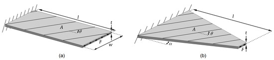
Figure 1.
Schematic diagrams of (a) non-tapered and (b) width-tapered cantilever laminated composite plates with identical thickness, length, and surface areas.
2.2. Stiffness Formulation
The laminate stiffness properties are described by means of lamination parameters, which are non-dimensional variables that govern the integral stiffness characteristics [32]. The studied laminates are assumed to consist of many homogenously distributed balanced layers. Therefore, the formulation involves two lamination parameters: and [33,34], which are defined as [35]
where N is the number of layers, are layer thicknesses, and are layer angles.
The values of the lamination parameters are constrained by the following relations [36]:
Figure 2 illustrates the feasible region of lamination parameters and sample design points with corresponding layer angles. The boundary points require certain layer angles during stacking-sequence retrieval, while many different configurations can be used for the interior points. The responses obtained with proper stacking-sequences converge to the solutions computed using the two lamination parameters for the increasing number of layers [37,38].
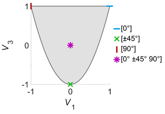
Figure 2.
Feasible region of lamination parameters and sample design points with corresponding layer angles.
Using the longitudinal modulus , transverse modulus , in-plane shear modulus , and major Poisson’s ratio ; the material invariants () used within the formulation are defined as follows [39]:
In terms of lamination parameters and material invariants, the constitutive matrix relating in-plane strains to stresses is stated as [35]
The constitutive matrix for the transverse shear deformation can be expressed as [39]
where and are transverse shear moduli.
The material properties of the graphite/epoxy laminae used in the present study are given in Table 1 [40]. The values are given as relations since the results are normalized and presented in non-dimensional form.

Table 1.
Material properties of the considered graphite/epoxy laminae.
2.3. Finite Element Analysis
The solutions are computed by finite element analyses that are performed using in-house software. The plates are discretized with linear 4-node isoparametric shell elements with three translational and two rotational degrees of freedom at each node. The formulation details for this first-order shear deformable element can be found in [41].
Through elemental stiffness matrix generation, domain discretization, and assembly procedures, the nodal stiffness matrix (K) is obtained. One should note that previously obtained constitutive matrices ( and ) are used within the elemental stiffness matrices. The nodal force vector (f) is defined by equally distributing the total in-plane shear force over the nodes at the tip. Then, K and f are modified to impose fixing boundary conditions at the clamped end. Finally, the nodal displacement vector (u) is calculated by solving the following global system of equations:
The element formulation is based on equivalent single layer theory, which is accurate for the analysis of thin to moderately thick laminates [42]. Hence, the plate thickness is selected such that the ratio ranges from 0.005 to 0.04 as the length is varied, while the ratio remains constant as 0.02. In addition, the plate deformations are assumed to be small due to the use of linear elastic formulation, and the computed responses are presented in non-dimensional form.
The plates with an ratio of 1.0 are discretized by using 10 elements in each direction, yielding a total of 100 elements (Figure 3). For meshing the other models, the number of elements along the longitudinal direction is varied proportionally to the ratio while retaining 10 elements along the width.
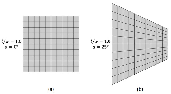
Figure 3.
Exemplary finite element meshes for (a) non-tapered and (b) width-tapered plates with .
2.4. Optimization
The optimization task is performed using genetic algorithms. For each aspect ratio, the lamination parameters and taper angle are optimized. Preliminary investigations showed that the optimal solutions appear on the boundary of the lamination parameter domain for the selected range of design variables. Hence, instead of the entire feasible domain, only the lower boundary of the lamination parameter space is searched by selecting as the design variable (). Such an optimization strategy has previously been suggested by Grenestedt [43]. The minimum and maximum possible values of the taper angle are defined as 0 (rectangular panel) and tan (triangular panel) radians, respectively. No additional constraints are imposed on the solution except the bounds on and . The values of and are restricted to be multiples of 0.01 and 1, respectively. The ‘ga.m’ function of MATLAB is used as the optimization tool.
3. Results and Discussion
In this section, the optimal results that minimize average tip displacements of the cantilever plates under shear load are presented. Three plate types (quasi-isotropic tapered (QI-T), stiffness-tailored rectangular (ST-R), and stiffness-tailored tapered (ST-T)) and four different aspect ratios () are considered.
First, the variation of the optimal design variables with respect to different design strategies and plate aspect ratios is investigated (Figure 4). All optimal lamination parameters appear on the lower boundary of the feasible domain. Since these points can be attained using angle-ply laminates, corresponding layer angles are also visualized. In comparison to QI-T plates, the optimal taper angles obtained for ST-T plates are slightly lower for () and larger for (). Compared to ST-R plates, optimal lamination parameters for ST-T plates spread further and lead to greater layer angles. Note that, neither optimal taper angles nor optimal layer angles remain unchanged when both variables are included within the design parameters. This result indicates the possible drawback of using a sequential approach for optimizing geometry and stiffness properties of laminate plates.
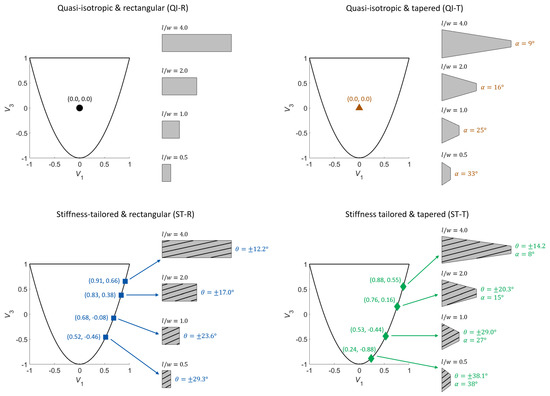
Figure 4.
Optimal lamination parameters with corresponding layer angles and taper angles for different design approaches and aspect ratios.
Optimal taper and layer angles vs. aspect ratio curves for different design approaches are also analyzed (Figure 5). Both optimal taper and layer angles decrease with increasing aspect ratio, where the former decreases with a greater rate. One can also note that the taper and layers angles of ST-T plates have very close values for (), while they draw apart for higher aspect ratios.
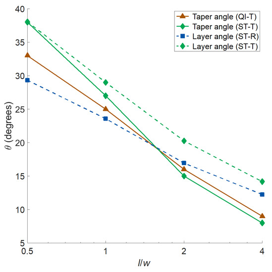
Figure 5.
Optimal taper and layer angles vs. aspect ratio plots for different design approaches.
Next, the influences of aspect ratio and design strategy on the optimal responses are analyzed. Figure 6 shows (a) the normalized tip displacements of cantilever plates under shear load and (b) displacement reduction percentage with respect to QI-R plates. The results indicate that ST-T plates yield the lowest mean displacements for all analyzed cases, indicating the importance of concurrently optimizing the layer and taper angles to attain the best performance. For all design approaches, the percent reduction compared to the QI-R rises with increasing aspect ratio. Sole tapering is more effective than sole stiffness tailoring for lower aspect ratios (), where the opposite holds true for higher aspect ratios ().
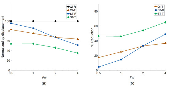
Figure 6.
The influences of aspect ratio and design strategy on (a) the normalized tip displacements of cantilever plates under shear load and (b) displacement reduction percentage compared to the quasi-isotropic rectangular plates.
Finally, deflection contours of the plates are obtained to further investigate the deformation mechanics governing the observed trends in the optimal design variables and responses. All four designs (QI-R, QI-T, ST-R, and ST-T) and two extreme nominal aspect ratios ( and ) are selected for this investigation.
Figure 7 shows the deflection contours, which demonstrate the relative lateral displacement magnitudes for each aspect ratio. The contours are normalized such that the value of the largest lateral displacement is 1.0 (red color), while the immobility at the clamped edges is denoted by 0.0 (blue color). The deflection profiles are visualized by preserving the proportions between different designs, while the exact displacement values are arbitrary.
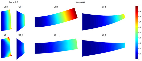
Figure 7.
Plate deflection contours for different designs and nominal aspect ratios.
The deflection profiles differ significantly with both panel design and aspect ratios. For , relatively large deformations are observed around the tip corners of the rectangular plates due to the dominant shear effects. The ST-R plate shows the largest of such local deformations, although it has a slightly lower average lateral tip displacement compared to the QI-R plate (see Figure 6). The tapering significantly reduces the corner deformations, which explains the greater effectiveness of sole tapering compared to stiffness tailoring alone.
Raising the value to 4.0 results in beam-like deformation profiles unlike the deflection shapes of the plates with a low aspect ratio where local effects are involved. Consequently, the relative effectiveness of sole tapering reduces, and the ST-R plate outperforms the QI-T one. The observed influence of increasing aspect ratio is related to the amplification of flexural deformation over shearing, as reported in the literature as well [8,10]. This transition in the dominant deformation mechanism also justifies the optimal fiber angle values, which are close to and for small and large aspect ratios, respectively.
The deflection contours also facilitate interpreting the growing effectiveness of all optimized designs with increasing aspect ratio. The low aspect ratio plates behave intrinsically stiffer due to the larger proportion of the fixed edge length. This characteristic disrupts the development of a regular deformation field along the plate length. A greater aspect ratio increases the relative length of the free edges potentially boosting the improvements that can be attained through optimization.
4. Conclusions
In this study, layer and taper angles of cantilever composite plates were concurrently optimized. The analyzed plates were subject to in-plane shear loads, and the average tip displacement was minimized as the design objective. The plate stiffness properties were modeled using lamination parameters to circumvent the solution dependency on the initial assumptions on the laminate configuration. The effectiveness of stiffness tailoring and tapering as well as the optimal layer and taper angles were investigated for several panel aspect ratios.
The optimal lamination parameters appeared at the lower boundary of the feasible domain for the studied problem. Since these points require especially orthotropic angle-ply laminates in the stacking-sequence retrieval, corresponding layer angles were also determined. Optimal taper and layer angles both decreased with increasing plate aspect ratio.
The optimization results showed that internal stiffness properties and plate geometry should both be exploited to minimize the deflection. In addition, the individually optimal layer and taper angles did not remain unchanged when they were simultaneously optimized. This result signifies the possible downside of using sequential optimization approaches in composite design studies. Moreover, tapering alone was found to be more effective than sole stiffness tailoring for low plate aspect ratios, while an opposite condition was observed for a large aspect ratio. However, the individual effectiveness of both approaches improved with the increasing aspect ratio.
Future work may address concurrent stiffness tailoring and tapering optimization in multi-axial loading scenarios. In addition, multi-objective optimization studies can be conducted to observe the conforming or conflicting behavior of different performance metrics.
Funding
This research received no external funding.
Institutional Review Board Statement
Not applicable.
Informed Consent Statement
Not applicable.
Data Availability Statement
The data presented in this study are available on request from the author.
Acknowledgments
The author acknowledges the Open Access publishing support by Max Planck Digital Library.
Conflicts of Interest
The author declares no conflict of interest.
Abbreviations
| QI-R | Quasi-isotropic and rectangular |
| QI-T | Quasi-isotropic and tapered |
| ST-R | Stiffness-tailored and rectangular |
| ST-T | Stiffness-tailored and tapered |
Nomenclature
| A | Plate area |
| Constitutive matrix for in-plane deformation | |
| Constitutive matrix for transverse shear deformation | |
| Longitudinal modulus | |
| Transverse modulus | |
| In-plane shear modulus | |
| , | Transverse shear moduli |
| F | Tip shear force |
| f | Nodal force vector |
| K | Nodal stiffness matrix |
| l | Plate length |
| N | Number of layers |
| t | Plate thickness |
| Layer thicknesses | |
| Material invariants | |
| u | Nodal displacement vector |
| , | Lamination parameters |
| w | Plate width |
| Taper angle | |
| Major Poisson’s ratio | |
| Layer angles |
References
- Wang, G.; Wereley, N.M. Free Vibration Analysis of Rotating Blades with Uniform Tapers. AIAA J. 2004, 42, 1531–1541. [Google Scholar] [CrossRef]
- Kim, T.U.; Hwang, I.H. Optimal design of composite wing subjected to gust loads. Comput. Struct. 2005, 83, 1546–1554. [Google Scholar] [CrossRef]
- Dado, M.; Al-Sadder, S. A new technique for large deflection analysis of non-prismatic cantilever beams. Mech. Res. Commun. 2005, 32, 692–703. [Google Scholar] [CrossRef]
- Ansari, M.Z.; Cho, C.; Kim, J.; Bang, B. Comparison between Deflection and Vibration Characteristics of Rectangular and Trapezoidal profile Microcantilevers. Sensors 2009, 9, 2706–2718. [Google Scholar] [CrossRef] [PubMed]
- Plaut, R.H.; Virgin, L.N. Optimal design of cantilevered elastica for minimum tip deflection under self-weight. Struct. Multidisc. Optim. 2011, 43, 657–664. [Google Scholar] [CrossRef]
- Kien, N.D.; Gan, B.S. Large deflections of tapered functionally graded beams subjected to end forces. Appl. Math. Model. 2014, 38, 3054–3066. [Google Scholar]
- Zhao, Z.; Feng, C.; Dong, Y.; Yang, J. Geometrically nonlinear bending of functionally graded nanocomposite trapezoidal plates reinforced with graphene platelets (GPLs). Int. J. Mech. Mater. Des. 2019, 15, 791–800. [Google Scholar] [CrossRef]
- Kılıc, O.; Aktas, A.; Dırıkolu, M.H. An investigation of the effects of shear on the deflection of an orthotropic cantilever beam by the use of anisotropic elasticity theory. Compos. Sci. Technol. 2001, 61, 2055–2061. [Google Scholar] [CrossRef]
- Thinh, T.I.; Ngoc, L.K. Static behavior and vibration control of piezoelectric cantilever composite plates and comparison with experiments. Comput. Mater. Sci. 2010, 49, s276–s280. [Google Scholar] [CrossRef]
- Vo, T.P.; Thai, H.-T. Static behavior of composite beams using various refined shear deformation theories. Compos. Struct. 2012, 94, 2513–2522. [Google Scholar] [CrossRef]
- Doeva, O.; Masjedi, P.K.; Weaver, P.M. Static deflection of fully coupled composite Timoshenko beams: An exact analytical solution. Eur. J. Mech. A Solids 2020, 81, 103975. [Google Scholar] [CrossRef]
- Bouadjadja, S.; Tati, A.; Guerira, B. Analytical and experimental investigations on large deflection analysis of composite cantilever beams. Mech. Adv. Mater. Struct. 2020, 1–9. [Google Scholar] [CrossRef]
- Franco Correia, V.M.; Mota Soares, C.M.; Mota Soares, C.A. Design sensitivity analysis and optimal design of composite structures using higher order discrete models. Eng. Optim. 1997, 29, 85–111. [Google Scholar] [CrossRef]
- Mota Soares, C.M.; Mota Soares, C.A.; Franco Correia, V.M. Optimization of multilaminated structures using higher-order deformation models. Comput. Methods. Appl. Mech. Eng. 1997, 149, 133–152. [Google Scholar]
- Kim, C.-G.; Hong, C.-S. Practical design of tapered composite structures using the manufacturing cost concept. Compos. Struct. 2001, 51, 285–299. [Google Scholar] [CrossRef]
- Öztürk, H.; Sabuncu, M. Stability analysis of a cantilever composite beam on elastic supports. Compos. Sci. Technol. 2005, 65, 1982–1995. [Google Scholar] [CrossRef]
- Karaagac, C.; Öztürk, H.; Sabuncu, M. Lateral dynamic stability analysis of a cantilever laminated composite beam with an elastic support. Int. J. Struct. Stab. Dyn. 2007, 7, 377–402. [Google Scholar] [CrossRef]
- Blasques, J.P.; Stolpe, M. Maximum stiffness and minimum weight optimization of laminated composite beams using continuous fiber angles. Struct. Multidisc. Optim. 2011, 43, 573–588. [Google Scholar] [CrossRef]
- Albazzan, M.A.; Harik, R.; Tatting, B.F.; Gürdal, Z. Efficient design optimization of nonconventional laminated composites using lamination parameters: A state of the art. Compos. Struct. 2019, 209, 362–374. [Google Scholar] [CrossRef]
- Serhat, G.; Faria, T.G.; Basdogan, I. Multi-objective optimization of stiffened, fiber-reinforced composite fuselages for mechanical and vibro-acoustic requirements. In Proceedings of the 17th AIAA/ISSMO Multidisciplinary Analysis and Optimization Conference, Washington, DC, USA, 13–17 June 2016. [Google Scholar]
- Serhat, G.; Basdogan, I. Effect of aspect ratio and boundary conditions on the eigenfrequency optimization of composite panels using lamination parameters. In Proceedings of the 11th ASMO-UK/ISSMO/NOED2016 International Conference on Numerical Optimisation Methods for Engineering Design, Munich, Germany, 18–20 July 2016. [Google Scholar]
- Serhat, G.; Basdogan, I. Multi-objective optimization of composite plates using lamination parameters. Mater. Design 2019, 180, 107904. [Google Scholar] [CrossRef]
- Serhat, G.; Basdogan, I. Comparison of vibro–acoustic performance metrics in the design and optimization of stiffened composite fuselages. In Proceedings of the 45th International Congress and Exposition on Noise Control Engineering (INTER–NOISE 2016), Hamburg, Germany, 21–24 August 2016. [Google Scholar]
- Serhat, G.; Basdogan, I. Design of curved composite panels for optimal dynamic response using lamination parameters. Compos. Part B Eng. 2018, 147, 135–146. [Google Scholar] [CrossRef]
- Hammer, V.B.; Bendsøe, M.P.; Lipton, R.; Pedersen, P. Parametrization in laminate design for optimal compliance. Int. J. Solids Struct. 1997, 34, 415–434. [Google Scholar] [CrossRef]
- Liu, S.; Hou, Y.; Sun, X.; Zhang, Y. A two-step optimization scheme for maximum stiffness design of laminated plates based on lamination parameters. Compos. Struct. 2012, 94, 3529–3537. [Google Scholar] [CrossRef]
- Setoodeh, S.; Abdalla, M.M.; Gürdal, Z. Design of variable–stiffness laminates using lamination parameters. Compos. Part B Eng. 2006, 37, 301–309. [Google Scholar] [CrossRef]
- Demir, E.; Yousefi-Louyeh, P.; Yildiz, M. Design of variable stiffness composite structures using lamination parameters with fiber steering constraint. Compos. Part B Eng. 2019, 165, 733–746. [Google Scholar] [CrossRef]
- Hong, Z.; Peeters, D.; Turteltaub, S. An enhanced curvature-constrained design method for manufacturable variable stiffness composite laminates. Comput. Struct. 2020, 238, 106284. [Google Scholar] [CrossRef]
- El Said, B.; Hallett, S.R. Multiscale surrogate modelling of the elastic response of thick composite structures with embedded defects and features. Compos. Struct. 2018, 200, 781–798. [Google Scholar] [CrossRef]
- Peeters, D.; van Baalen, D.; Abdallah, M. Combining topology and lamination parameter optimisation. Struct. Multidisc. Optim. 2015, 52, 105–120. [Google Scholar] [CrossRef]
- Tsai, S.W.; Hahn, H.T. Introduction to Composite Materials, 1st ed.; Technomic: Lancaster, UK, 1980; pp. 123–131. [Google Scholar]
- Grenestedt, J.L. Layup optimization and sensitivity analysis of the fundamental eigenfrequency of composite plates. Compos. Struct. 1989, 12, 193–209. [Google Scholar] [CrossRef]
- Fukunaga, H.; Vanderplaats, G.N. Stiffness optimization of orthotropic laminated composites using lamination parameters. AIAA J. 1991, 29, 641–646. [Google Scholar] [CrossRef]
- Gürdal, Z.; Haftka, R.T.; Hajela, P. Design and Optimization of Laminated Composite Materials, 1st ed.; John Wiley & Sons: New York, NY, USA, 1999; p. 140. [Google Scholar]
- Fukunaga, H.; Sekine, H.; Sato, M. Optimal design of symmetric laminated plates for fundamental frequency. J. Sound Vibrat. 1994, 171, 219–229. [Google Scholar] [CrossRef]
- Serhat, G.; Basdogan, I. Lamination parameter interpolation method for design of manufacturable variable-stiffness composite panels. AIAA J. 2019, 57, 3052–3065. [Google Scholar] [CrossRef]
- Serhat, G.; Bediz, B.; Basdogan, I. Unifying lamination parameters with spectral-Tchebychev method for variable-stiffness composite plate design. Compos. Struct. 2020, 242, 112183. [Google Scholar] [CrossRef]
- Diaconu, C.G.; Sato, M.; Sekine, H. Layup optimization of symmetrically laminated thick plates for fundamental frequencies using lamination parameters. Struct. Multidisc. Optim. 2002, 24, 302–311. [Google Scholar] [CrossRef]
- Serhat, G.; Anamagh, M.R.; Bediz, B.; Basdogan, I. Dynamic analysis of doubly curved composite panels using lamination parameters and spectral-Tchebychev method. Comput. Struct. 2020, 239C, 106294. [Google Scholar] [CrossRef]
- Liu, G.R.; Quek, S.S. The Finite Element Method: A Practical Course, 1st ed.; Butterworth-Heinemann: London, UK, 2003; pp. 180–184. [Google Scholar]
- Reddy, J.N. Mechanics of Laminated Composite Plates and Shells: Theory and Analysis, 2nd ed.; CRC Press: Boca Raton, FL, USA, 2003; p. 112. [Google Scholar]
- Grenestedt, J.L. Composite plate optimization only requires one parameter. Struct. Optim. 1990, 2, 29–37. [Google Scholar] [CrossRef]


Publisher’s Note: MDPI stays neutral with regard to jurisdictional claims in published maps and institutional affiliations. |
© 2021 by the author. Licensee MDPI, Basel, Switzerland. This article is an open access article distributed under the terms and conditions of the Creative Commons Attribution (CC BY) license (https://creativecommons.org/licenses/by/4.0/).