
Study on Interference Connection Based on Shape Recovery of NiTiNb Shape Memory Alloy

Abstract
:1. Introduction
2. Materials and Methods
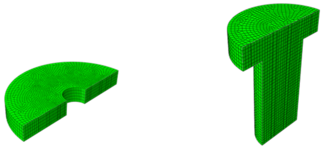
2.1. Numerical Simulation of Interference Connection
2.1.1. Model Creation
2.1.2. Material Properties
2.1.3. Parameter Setting
2.2. Experiment of Interference Connection
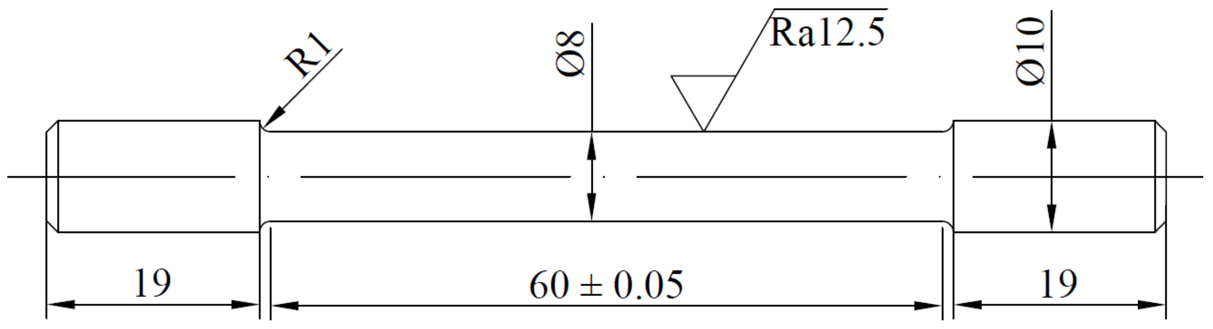
2.2.1. Materials
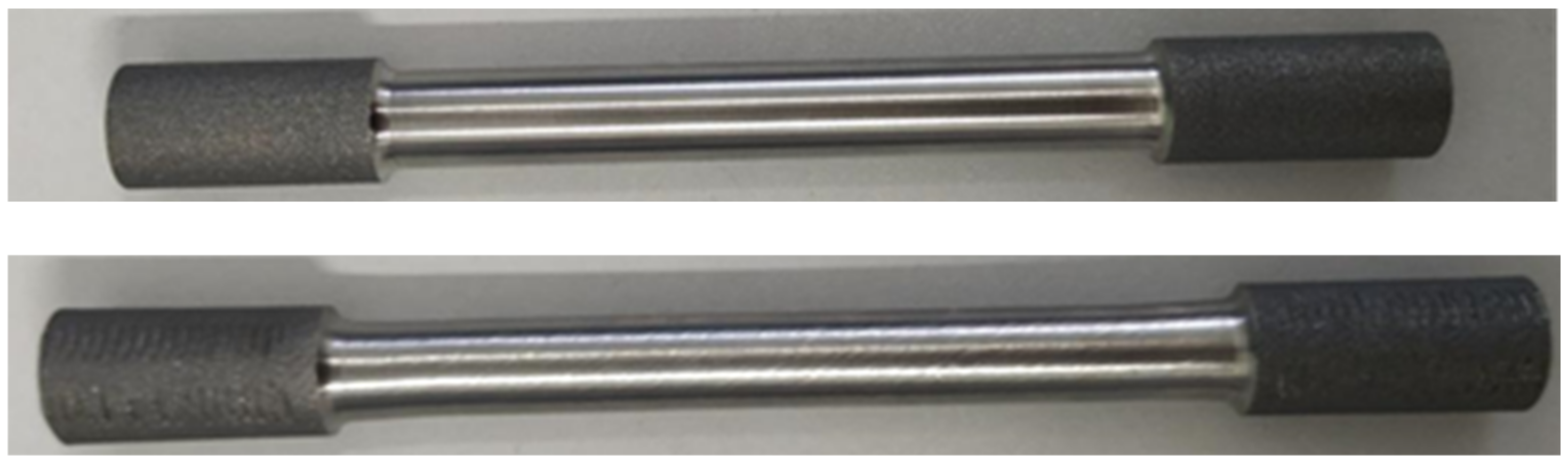
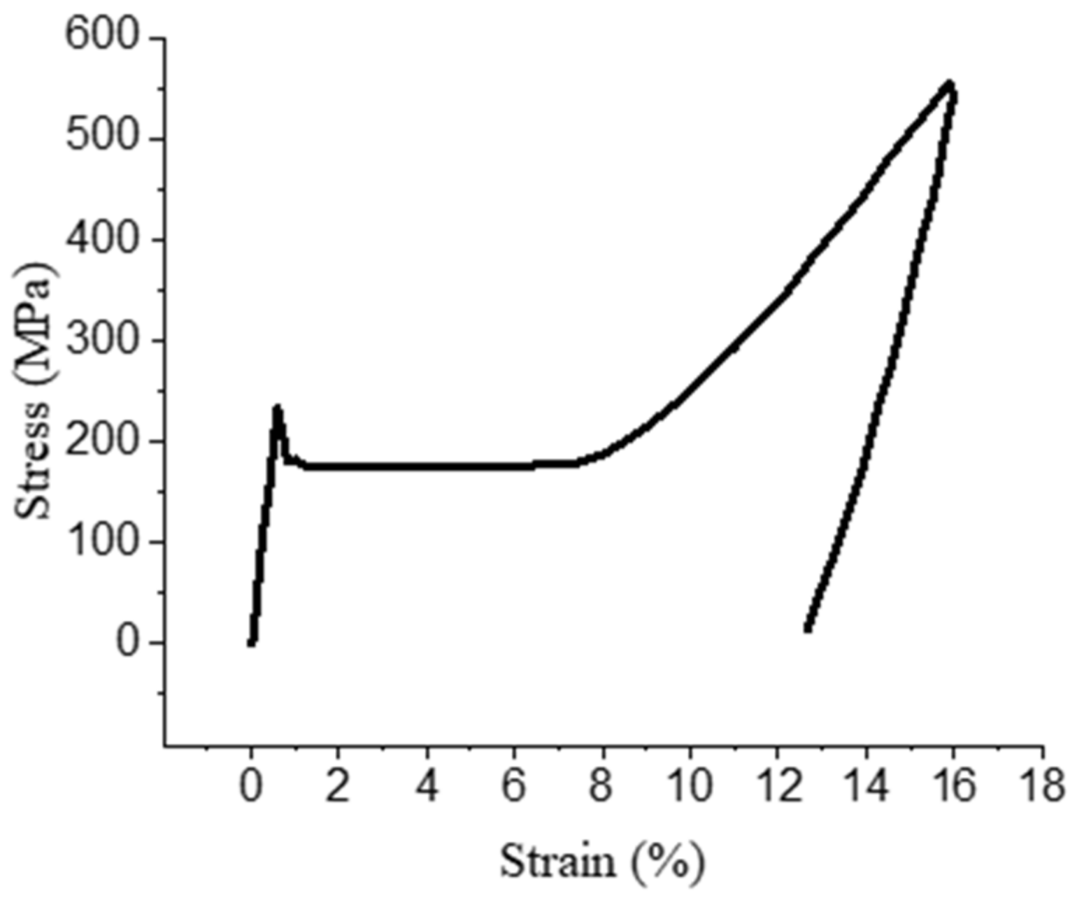
2.2.2. Tensile Pre-Deformation
2.2.3. Heating Recovery
2.2.4. Interference Connection
2.2.5. Interference Force Measurement
3. Results and Discussions
3.1. Analysis of Numerical Simulation Stress
3.2. Analysis of Numerical Simulation Strain
3.3. Analysis of Interference Force
4. Conclusions
- (1)
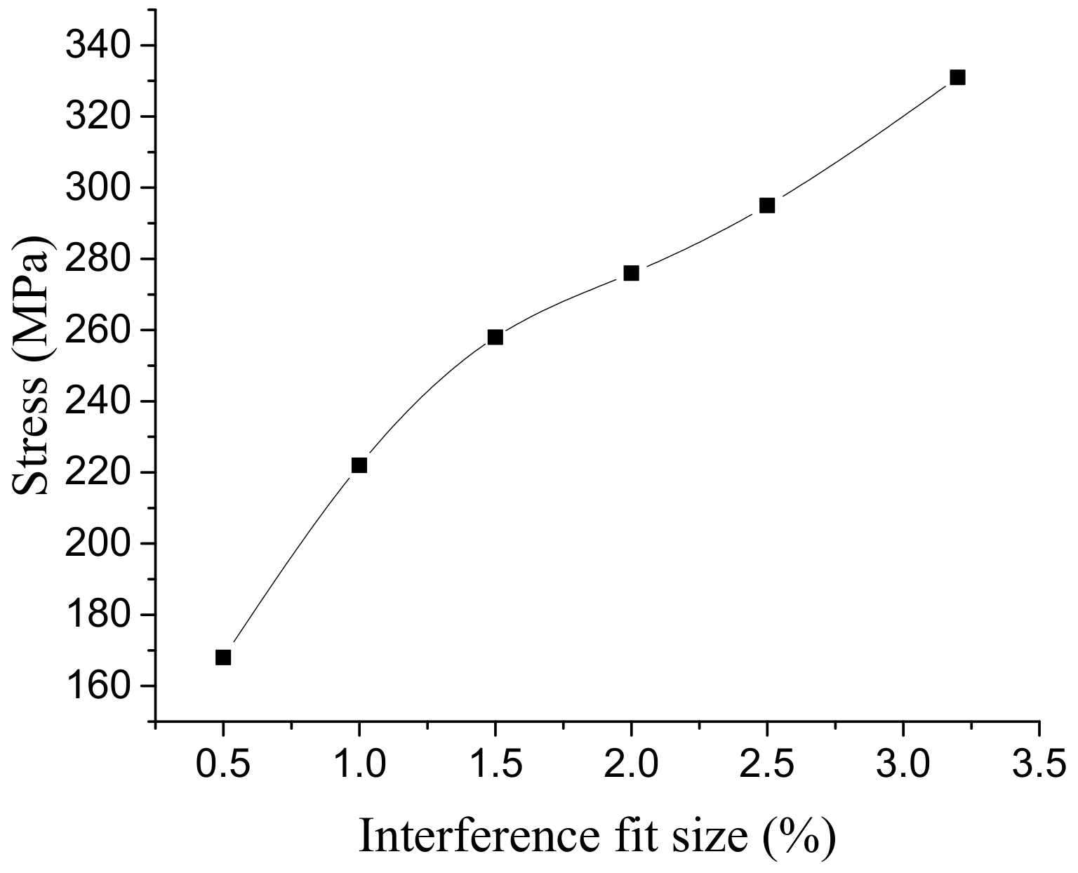
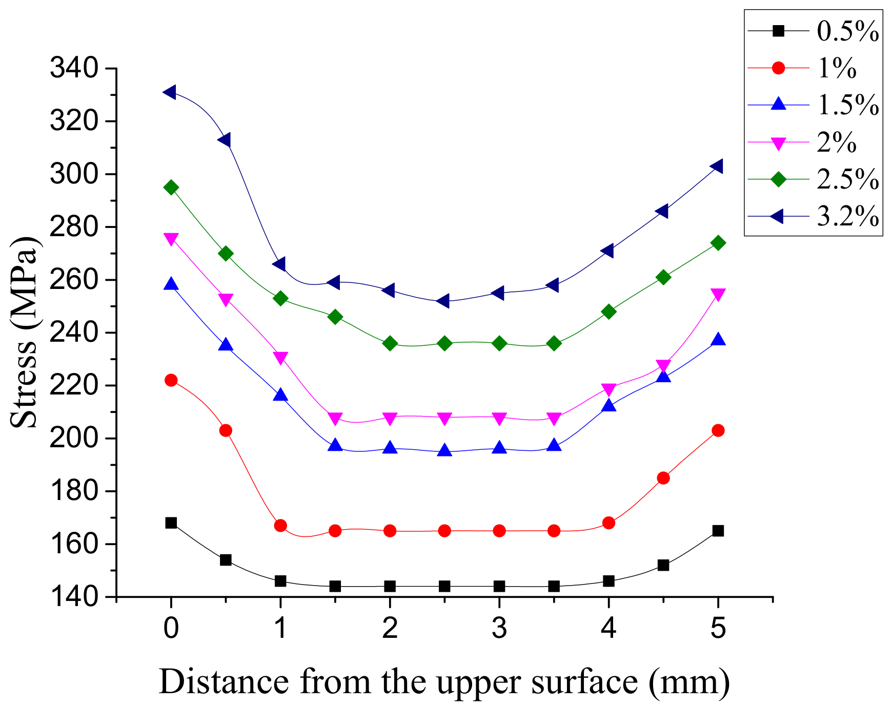
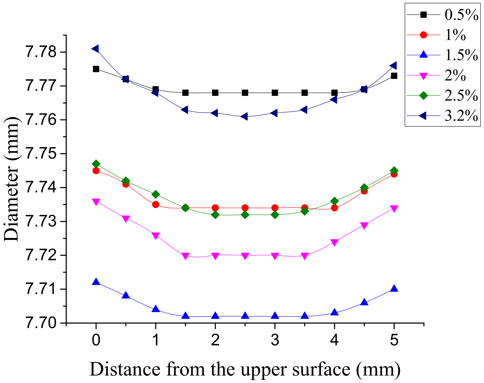
- The results of numerical simulation show that the method of interference connection using SMA can achieve large interference fit size connection, and the maximum interference fit size with aluminum alloy connecting plate was about 2.5%. There was no bump in the resulting interference connection. There was a stress concentration at the root of the bolt, and the stress distribution of the hole wall was uniform.
- (2)
- When the interference fit size was less than 1%, the connection hole had elastic deformation. When the interference fit size was 1.5%, the hole wall had plastic deformation. When the interference fit size was 2.5%, the maximum stress on the connecting plate was close to the tensile limit of the material. If the interference fit size continues to increase, the strength of the connection structure will be damaged.
- (3)
- The results of the interference connection test show that there was no bump after the interference connection was completed. The interference force was calculated by pulling-off force, and the interference force increased with the increase in interference fit size. Compared with the results of finite element analysis, the change trend of the interference force is basically the same, and the error is less than 13%, which verifies the rationality of the finite element simulation.
Author Contributions
Funding
Conflicts of Interest
References
- Taghizadeh, H.; Chakherlou, T.N.; Ghorbani, H.; Mohammadpour, A. Prediction of fatigue life in cold expanded fastener holes subjected to bolt tightening in Al alloy 7075-T6 plate. Int. J. Mech. Sci. 2015, 90, 6–15. [Google Scholar] [CrossRef]
- Croccolo, D.; Agostinis, M.D.; Ceschini, L.; Morri, A.; Marconi, A. Interference fit effect on improving fatigue life of a holed single plate. Fatigue Fract. Eng. Mater. Struct. 2013, 36, 689–698. [Google Scholar] [CrossRef]
- Kim, S.Y.; Hennigan, D.J.; Kim, D.; Seok, C.S. Fatigue enhancement by interference-fit in a pin-loaded glass fibre-reinforced plastics laminate. J. Mech. Eng. Sci. 2012, 226, 1437–1446. [Google Scholar] [CrossRef]
- Jani, M.J.; Leary, M.; Subic, A.; Gibson, M.A. A review of shape memory alloy research, applications and opportunities. Mater. Des. 2014, 56, 1078–1113. [Google Scholar] [CrossRef]
- Duerig, T.; Pelton, A.; Stöckel, D. An overview of nitinol medical applications. Mater. Sci. Eng. A 1999, 273, 149–160. [Google Scholar] [CrossRef]
- Kajiwara, S.; Baruj, A.L.; Kikuchi, T.; Shinya, N. Low-cost high-quality Fe-based shape memory alloys suitable for pipe joints. Proc. SPIE Int. Soc. Opt. Eng. 2003, 5053, 250–261. [Google Scholar]
- Shishkin, S.V.; Shishkin, S.S. The application of rivets with shape memory in aeronautical engineering. J. Mach. Manuf. Reliab. 2010, 39, 179–184. [Google Scholar] [CrossRef]
- Humbeeck, J.V. Non-medical applications of shape memory alloys. Mater. Sci. Eng. A 1999, 273, 134–148. [Google Scholar] [CrossRef]
- Sun, L.; Huang, W.M.; Ding, Z.; Zhao, Y.; Wang, C.C.; Purnawali, H.; Tang, C. Stimulus-responsive shape memory materials: A review. Mater. Des. 2012, 33, 577–640. [Google Scholar] [CrossRef]
- Otsuka, K.; Ren, X. Physical metallurgy of Ti–Ni-based shape memory alloys. Prog. Mater. Sci. 2005, 50, 511–678. [Google Scholar] [CrossRef]
- Wang, M.; Jiang, M.; Liao, G.; Guo, S.; Zhao, X. Martensitic transformation involved mechanical behaviors and wide hysteresis of NiTiNb shape memory alloys. Prog. Nat. Sci. Mater. Int. 2012, 22, 130–138. [Google Scholar] [CrossRef] [Green Version]
- Jiang, J.F.; Bi, Y.; Dong, H.; Ke, Y.; Fan, X.; Du, K. Influence of interference fit size on hole deformation and residual stress in hi-lock bolt insertion. J. Mech. Eng. Sci. 2014, 228, 3296–3305. [Google Scholar] [CrossRef]
- Thamburaja, P. Constitutive equations for martensitic reorientation and detwinning in shape memory alloys. J. Mech. Phys. Solids 2005, 53, 825–856. [Google Scholar] [CrossRef]
- Brinson, L.C.; Huang, M.S. Simplifications and Comparisons of Shape Memory Alloy Constitutive Models. J. Intell. Mater. Syst. Struct. 1996, 7, 108–114. [Google Scholar] [CrossRef]


| Material | Property | Value |
|---|---|---|
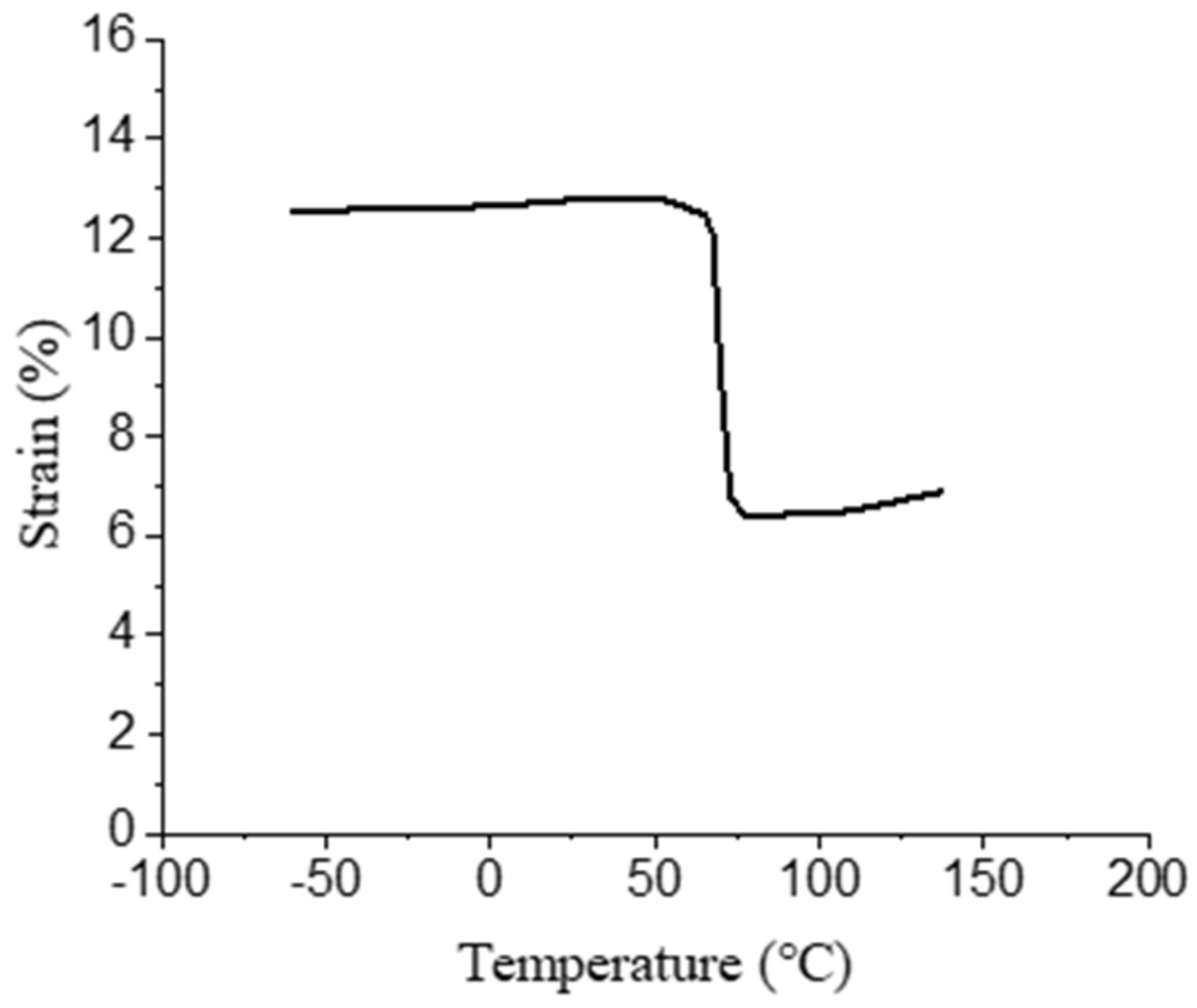
| NiTiNb | Austenite transformation As′ | 63 °C |
| Austenite transformation Af′ | 125 °C | |
| Maximum recoverable strain | 7% | |
| Modulus of elasticity E | 89,088 MPa | |
| Poisson ratio v | 0.39 | |
| Yield strength σs | 520 MPa | |
| Aluminium alloy 6061-T651 | Modulus of elasticity E | 72,000 MPa |
| Poisson ratio v | 0.33 | |
| Yield strength σs | 240 MPa | |
| Friction factor μ | 0.15 |
| Interference Fit Size | 0.5% | 1% | 1.5% | 2% | 2.5% | 3.2% |
| Shaft d/mm | 7.544 | |||||
| Hole D/mm | 7.752 | 7.714 | 7.676 | 7.638 | 7.601 | 7.544 |
| Modulus of Elasticity | Yield Strength | Breaking Strength | Percentage Elongation |
|---|---|---|---|
| 87 GPa | 800 MPa | 500 MPa | 30% |
| Number | Before Tension | After Tension | After Recovery | Recovery Rate | ||||
|---|---|---|---|---|---|---|---|---|
| Length/mm | Diameter/mm | Length/mm | Diameter/mm | Length/mm | Diameter/mm | Length/mm | Diameter/mm | |
| 1 | 60.23 | 7.97 | 67.46 | 7.53 | 64.28 | 7.71 | 5.27 | 2.26 |
| 2 | 60.39 | 7.99 | 67.53 | 7.52 | 64.59 | 7.69 | 4.87 | 2.12 |
| 3 | 60.18 | 8.00 | 67.61 | 7.54 | 64.35 | 7.73 | 5.42 | 2.39 |
| 4 | 60.56 | 8.01 | 67.59 | 7.54 | 64.48 | 7.72 | 5.14 | 2.25 |
| 5 | 59.89 | 7.97 | 67.49 | 7.53 | 64.37 | 7.69 | 5.21 | 2.01 |
| 6 | 60.31 | 7.99 | 67.42 | 7.51 | 64.41 | 7.68 | 4.99 | 2.13 |
| Interference Fit Size | 0.5% | 1% | 1.5% | 2% | 2.39% |
| Shaft d/mm | 7.54 | ||||
| Hole D/mm | 7.69 | 7.65 | 7.61 | 7.57 | 7.54 |
Publisher’s Note: MDPI stays neutral with regard to jurisdictional claims in published maps and institutional affiliations. |
© 2021 by the authors. Licensee MDPI, Basel, Switzerland. This article is an open access article distributed under the terms and conditions of the Creative Commons Attribution (CC BY) license (https://creativecommons.org/licenses/by/4.0/).
Share and Cite
Niu, H.; Sun, Y.; Lin, C.; Zou, Y. Study on Interference Connection Based on Shape Recovery of NiTiNb Shape Memory Alloy. Materials 2021, 14, 2328. https://doi.org/10.3390/ma14092328
Niu H, Sun Y, Lin C, Zou Y. Study on Interference Connection Based on Shape Recovery of NiTiNb Shape Memory Alloy. Materials. 2021; 14(9):2328. https://doi.org/10.3390/ma14092328
Chicago/Turabian StyleNiu, Haojie, Yubin Sun, Chengxin Lin, and Yutang Zou. 2021. "Study on Interference Connection Based on Shape Recovery of NiTiNb Shape Memory Alloy" Materials 14, no. 9: 2328. https://doi.org/10.3390/ma14092328