
Development of Measurement Equipment and Experimental and Numerical Simulation Studies for Warm Forming Limits of High-Strength Steel


Abstract
:1. Introduction
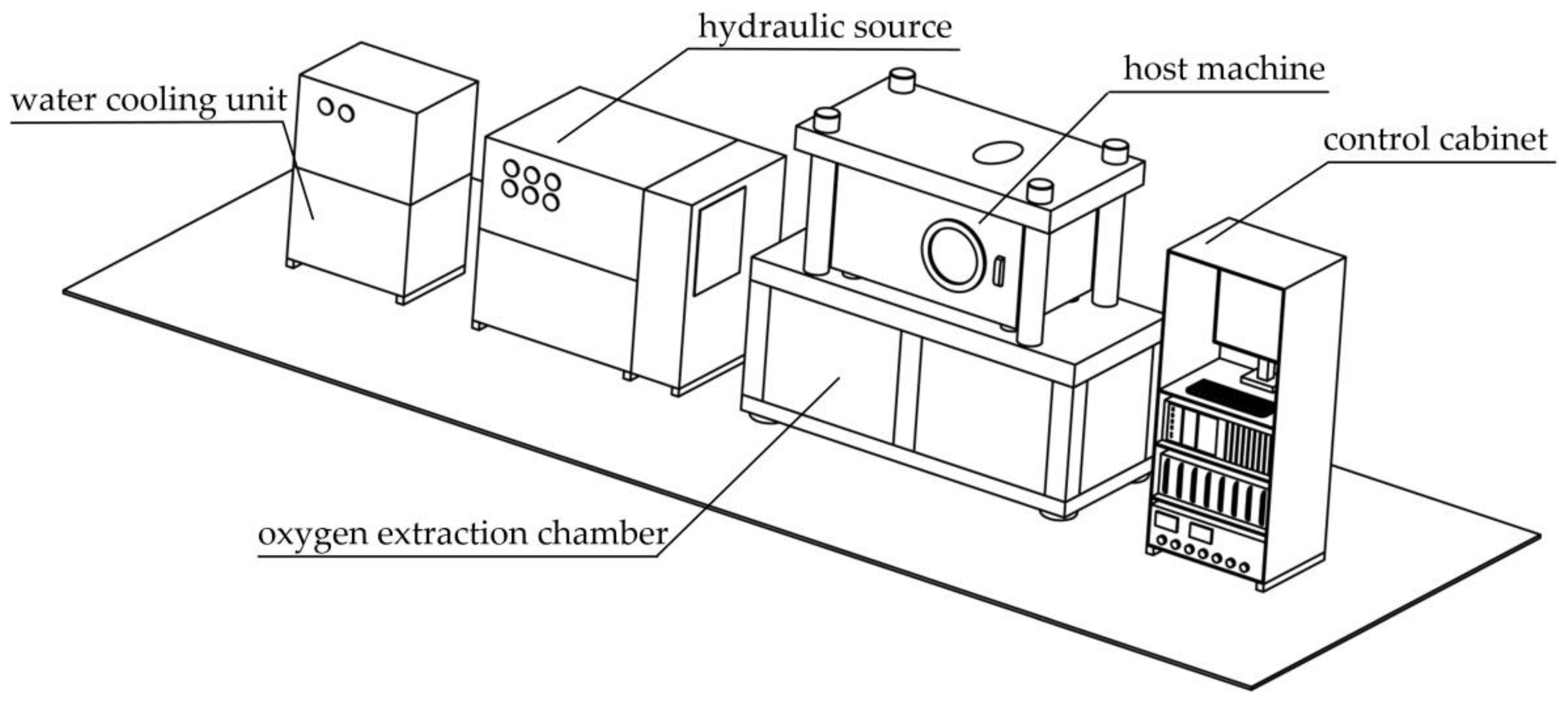
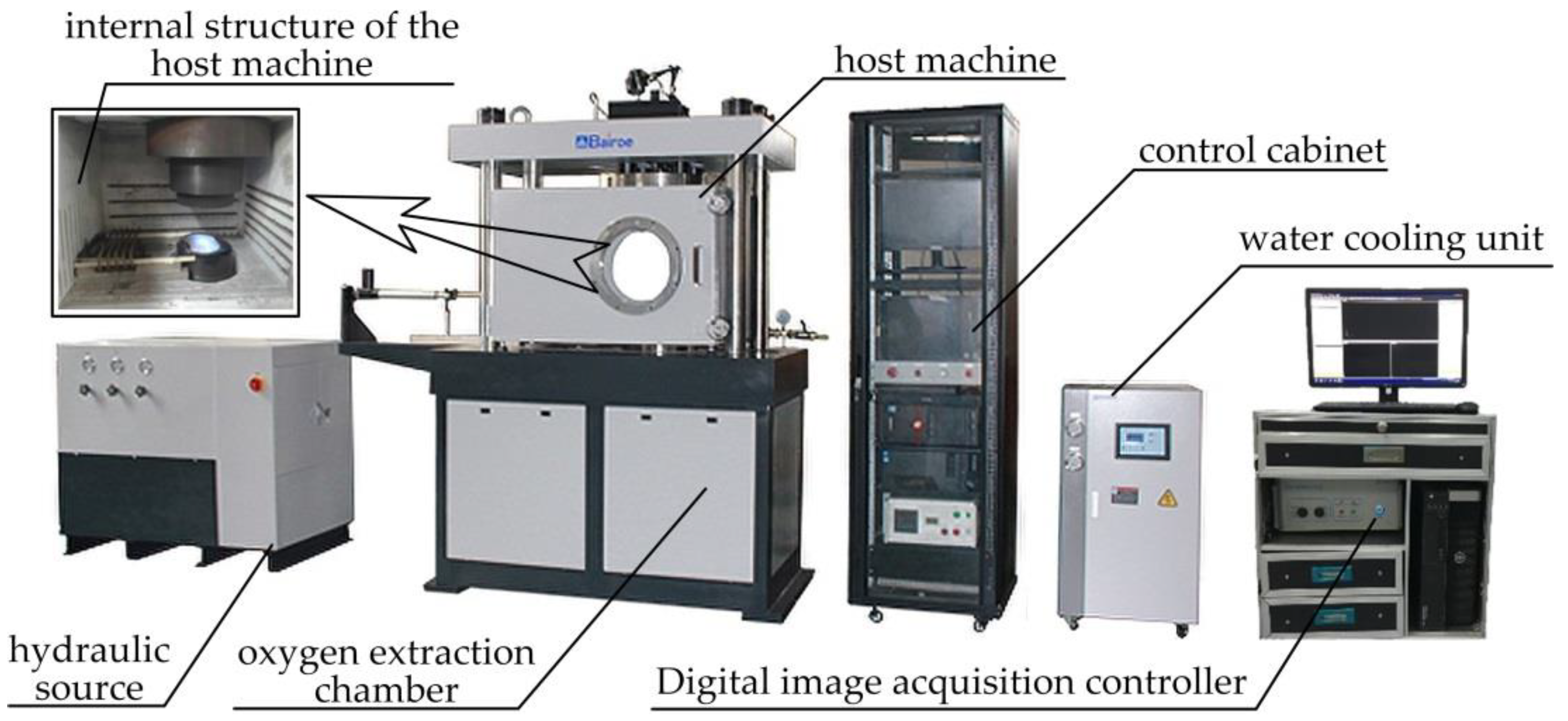
2. Design of Warm-Forming-Limit Measurement Equipment
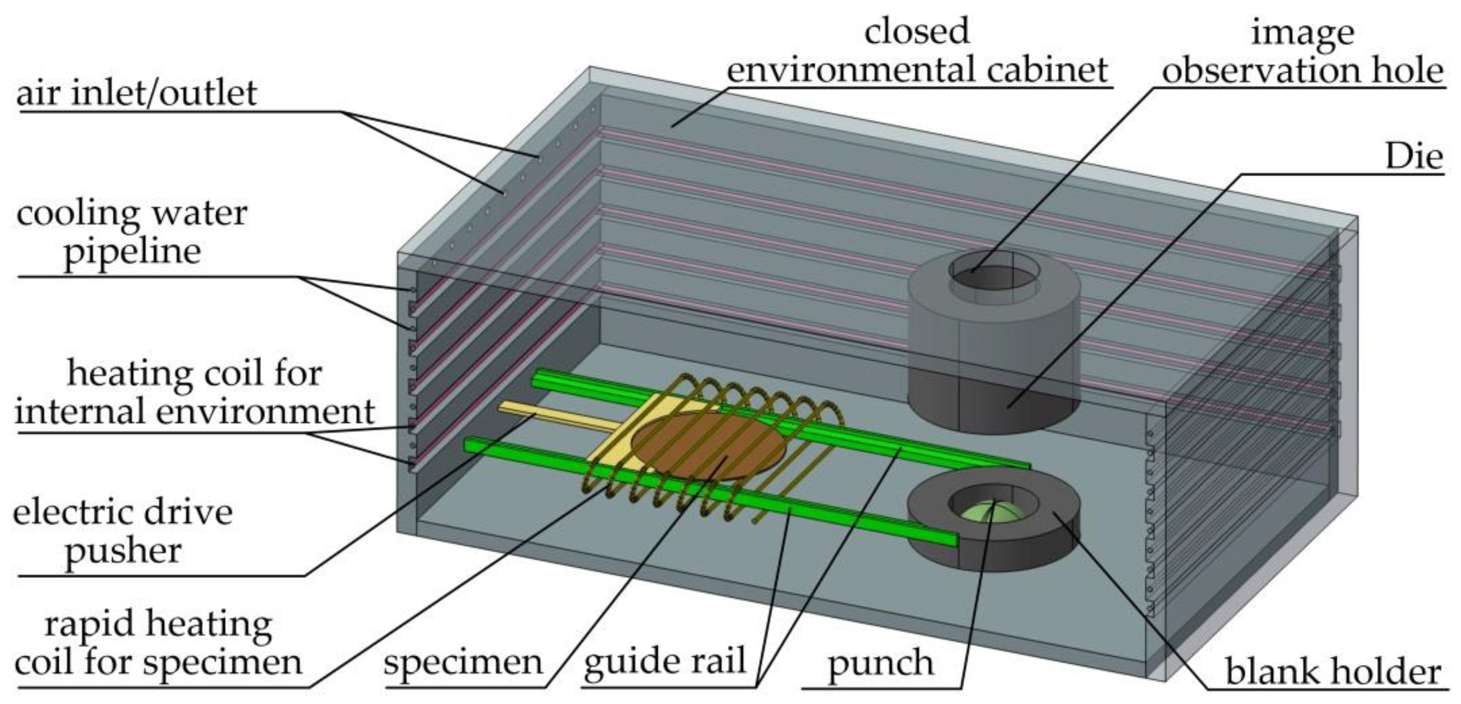
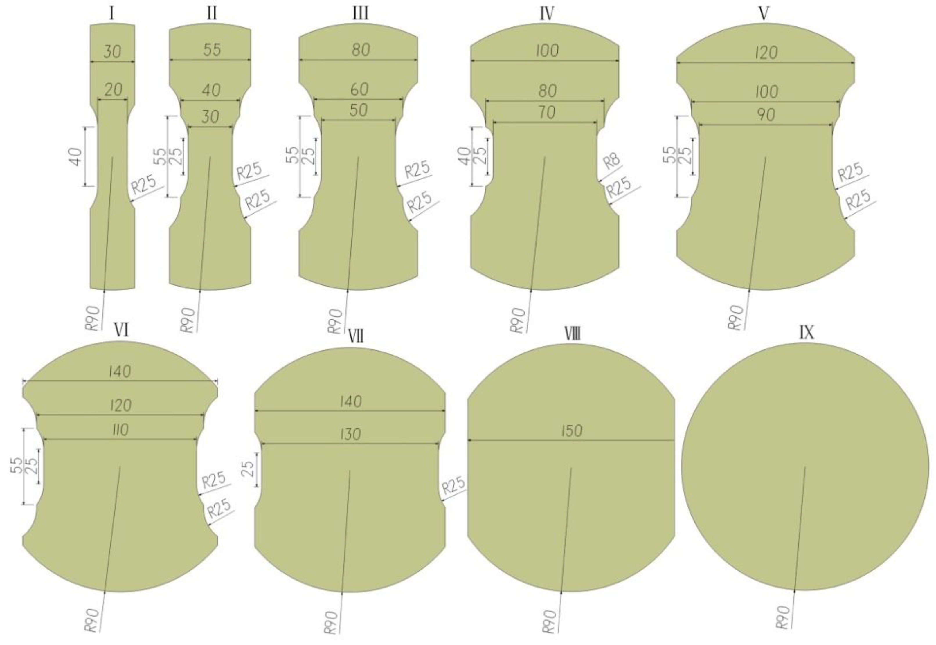
2.1. Structural Design of the Part for Warm Forming
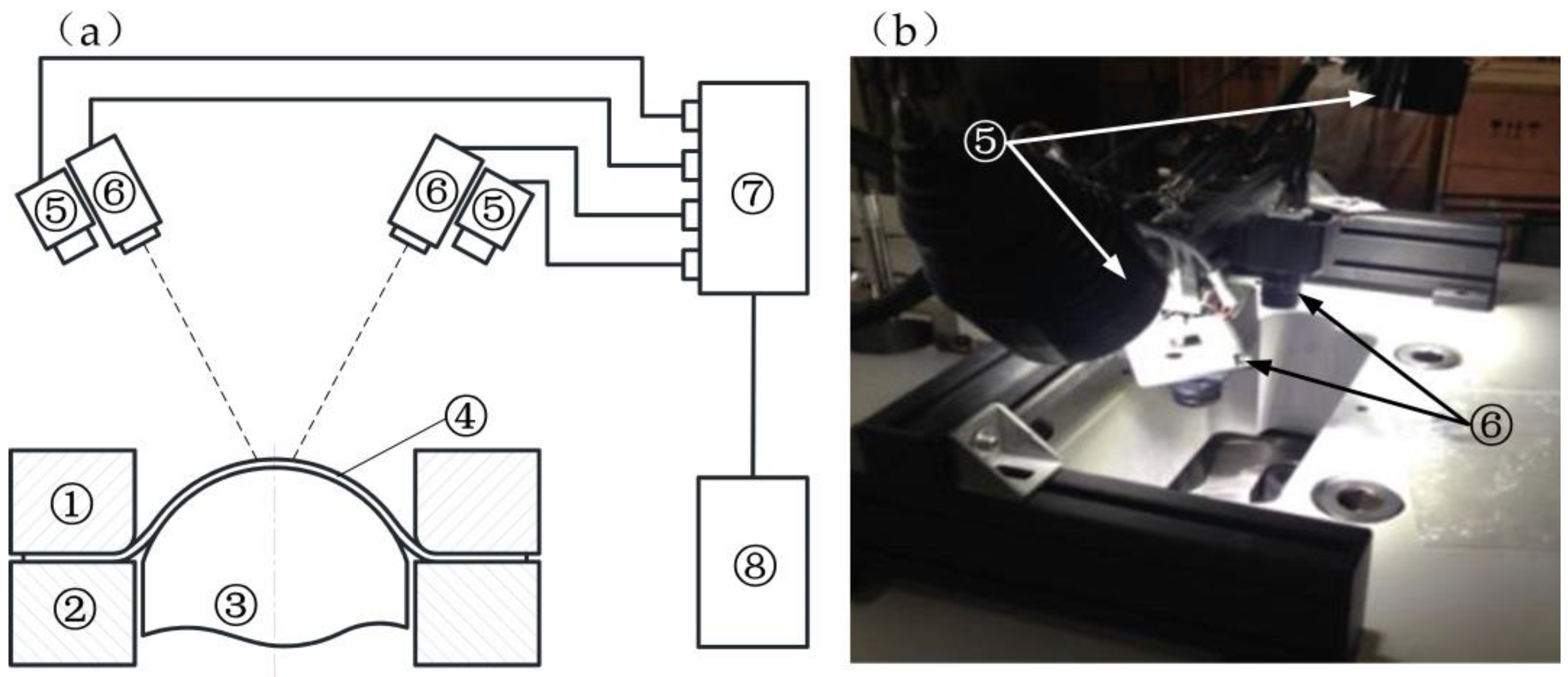
2.2. Design of the Digital Image Measurement Part
2.3. Working Procedures
- Camera calibration: Adjust the direction of the two LED light sources to ensure that the light can pass through the glass above the host and that there is light on the specimen. Use the two cameras to shoot the calibration board from different directions to acquire images, identify the three-dimensional coordinates of the calibration points, and obtain the accurate inner parameters and external position parameters of the cameras through calculations, thus preparing for the acquisition of images in the experimental process.
- Argon gas is injected through the air inlet to exhaust the oxygen so as to reach the preset values of pressure.
- Heat the internal space environment of the chamber to the preset temperature and keep the temperature constant.
- The specimen is pushed with the electric drive pusher to the preset position on the blank holder along the guide rail. The specimen gradually rises to the same temperature as the space environment inside the closed cabinet. If the specimen needs to be heated rapidly, according to the specific experimental parameters, it is quickly heated to the preset temperature with a rapid heating coil, and then moved along the guide rail to the preset position on the blank holder with the electric drive pusher.
- Start the hydraulic system and control the displacement to make the blank holder move upward until the lifted specimen is under the plane joint with the die. The blank holder will then continuously and tightly press the specimen with the preset force. The punch will move upward according to the forming speed in the settings, and the bulging experiment process is started after making contact with the specimen. Serial images of the specimen will be collected over the whole forming process. If quenching is required for the specimen in the process, the water-cooling unit can be opened and the corresponding cooling rate can be set. In terms of experiments without any phase changes in the specimen, the water-cooling unit may also be started after the forming of the specimen to cool down the specimen and die in the heating furnace in order to facilitate the removal of the specimen.
- Use the forming-limit measurement software developed to carry out procedures such as “define the computing area and conduct the digital speckle matching and computing”, “calculate the surface strain field”, and “generate cross section in the obtained strain field to acquire the limiting strain” to obtain the maximum and minimum strain limits of the specimen. The specific information can be found in our previously published literature [16].
3. Materials and Methods
3.1. Specimen
3.2. Warm-Forming and Room-Temperature-Forming Experiments
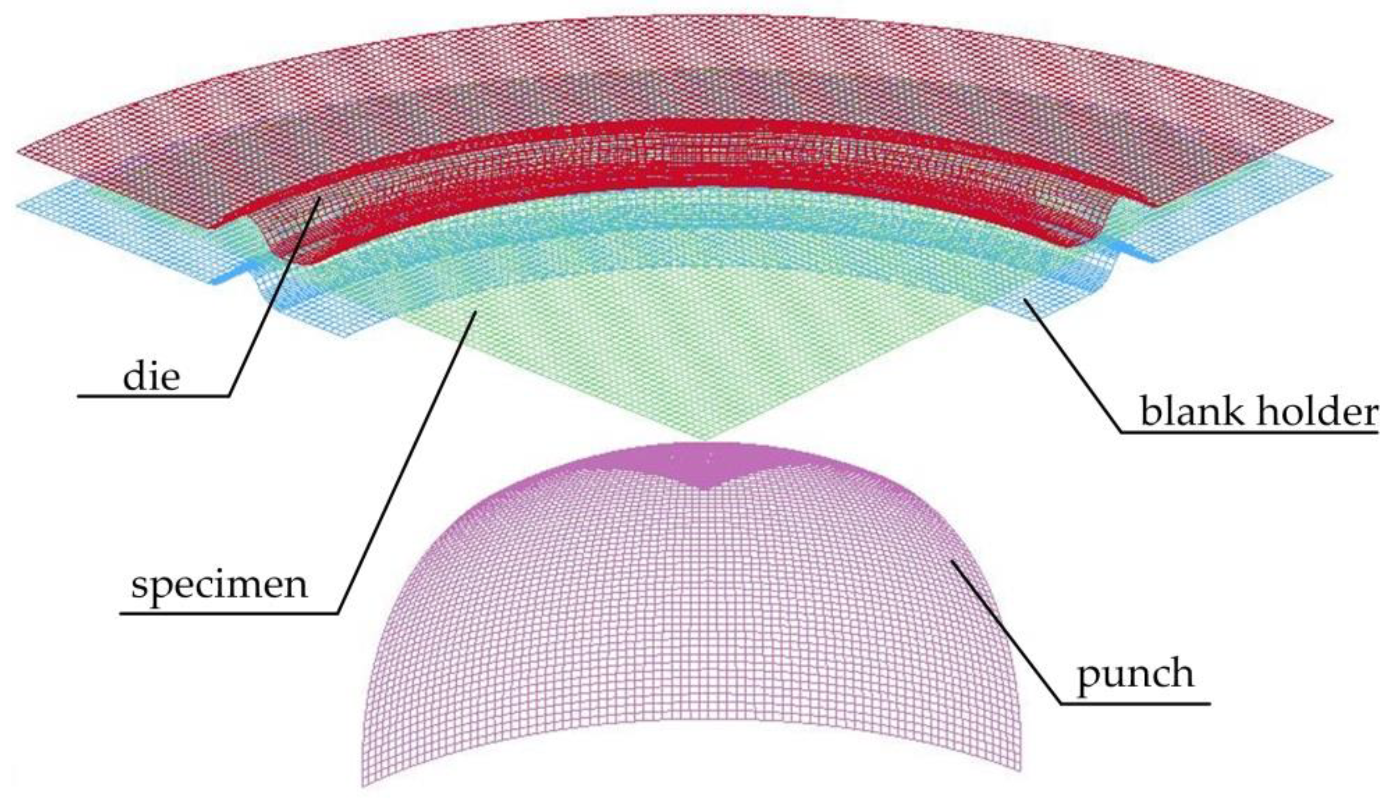
3.3. Numerical Simulation
4. Results and Discussion
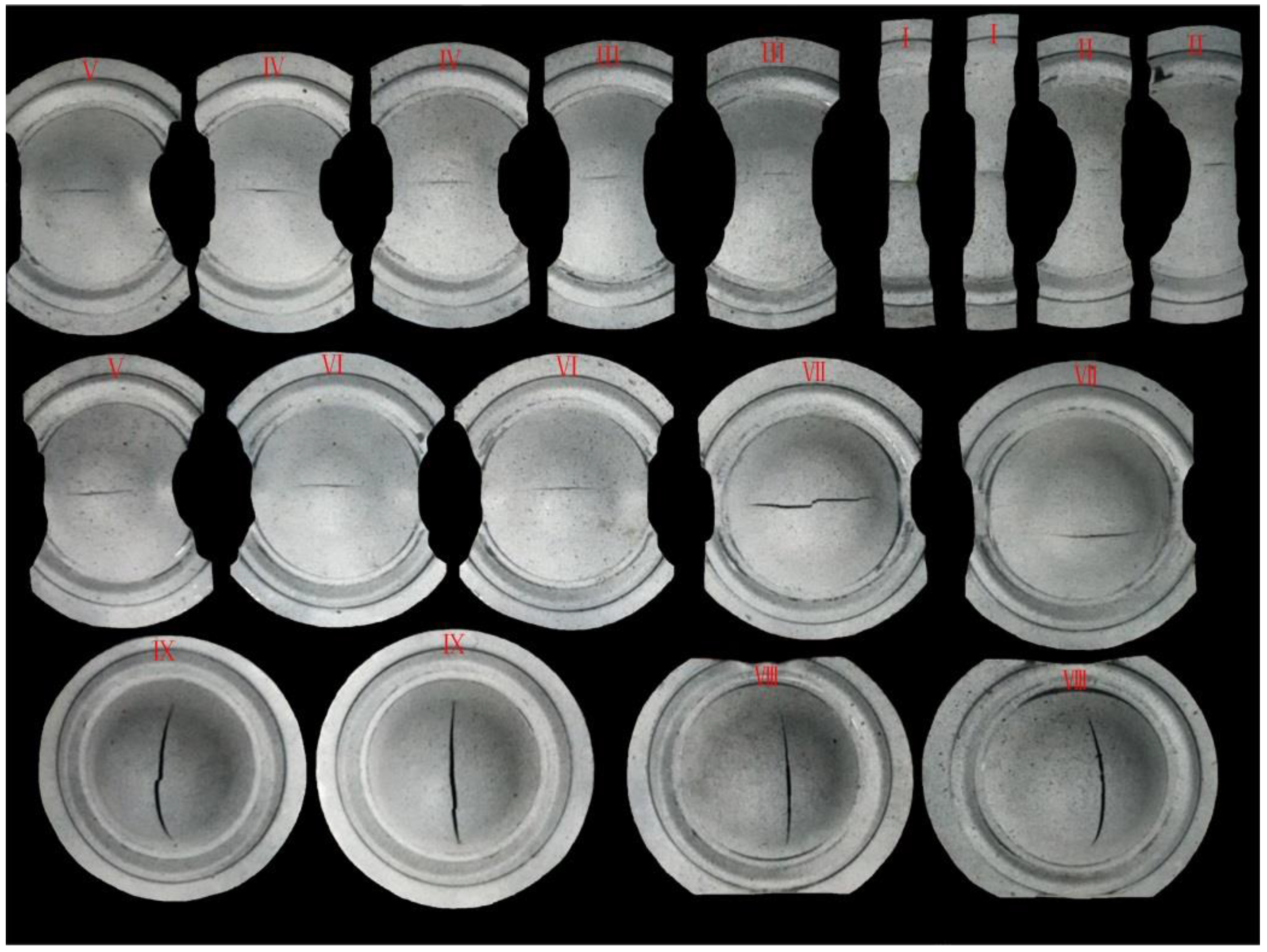
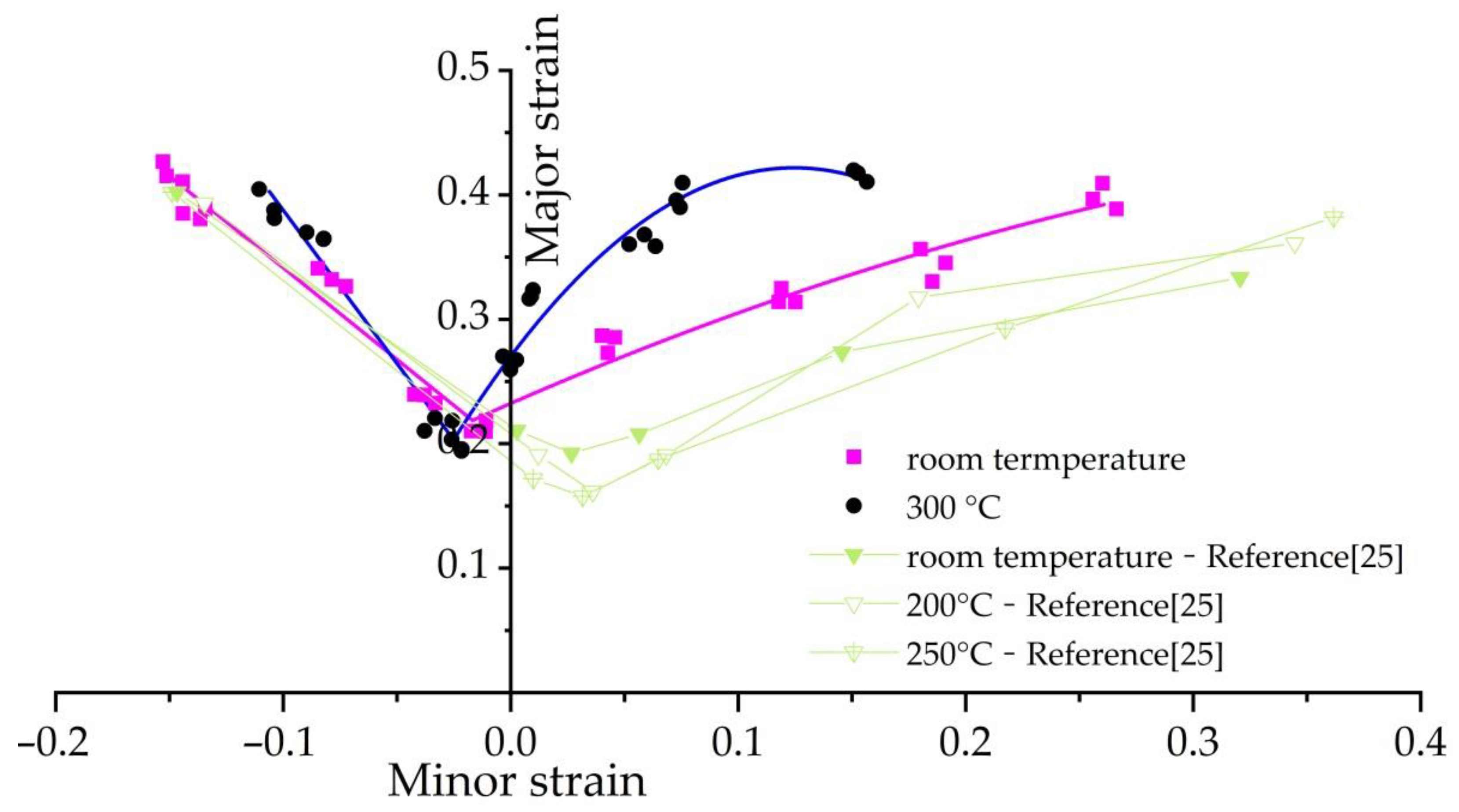
4.1. Experimental Results
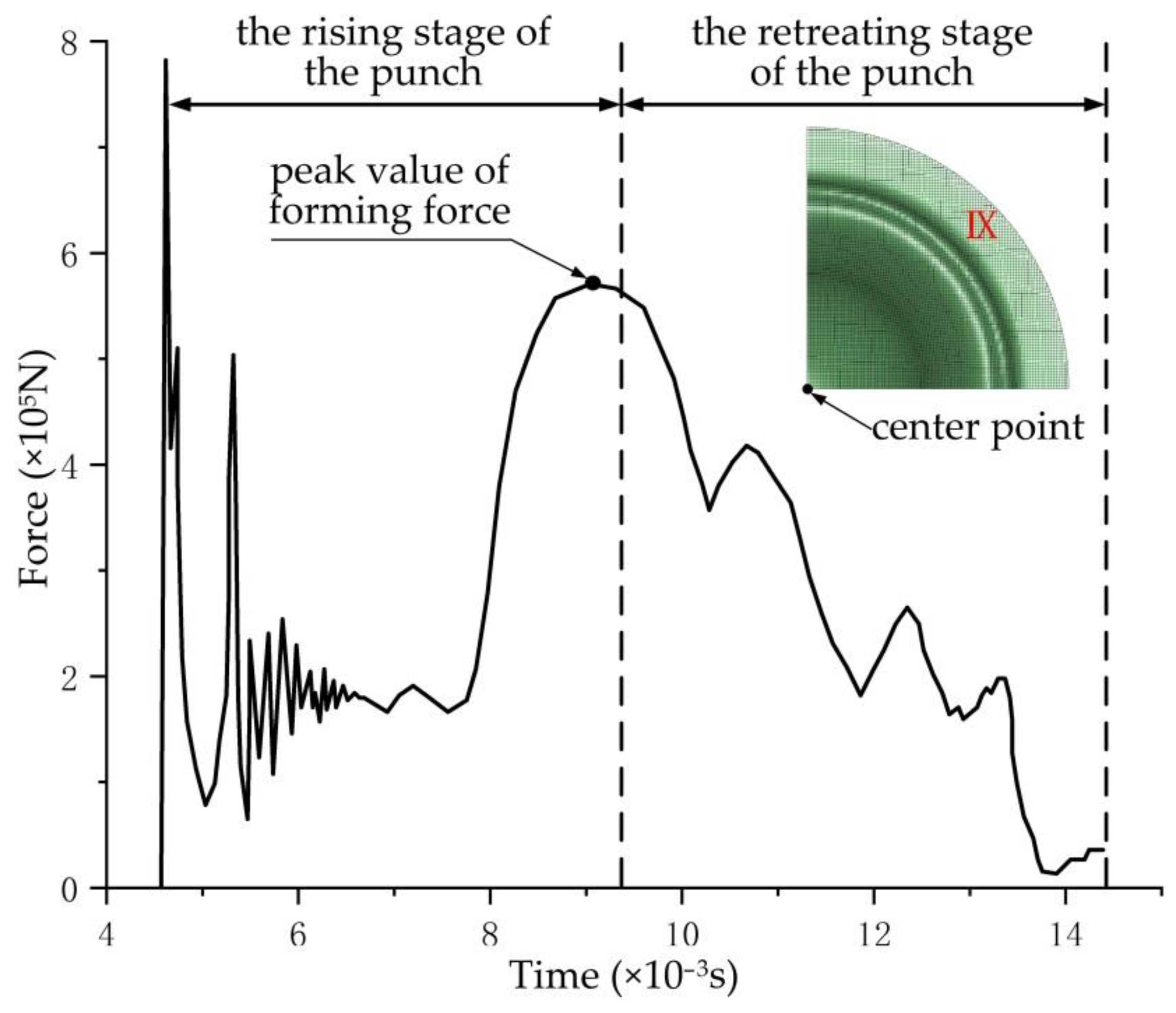
4.2. Numerical Simulation Results
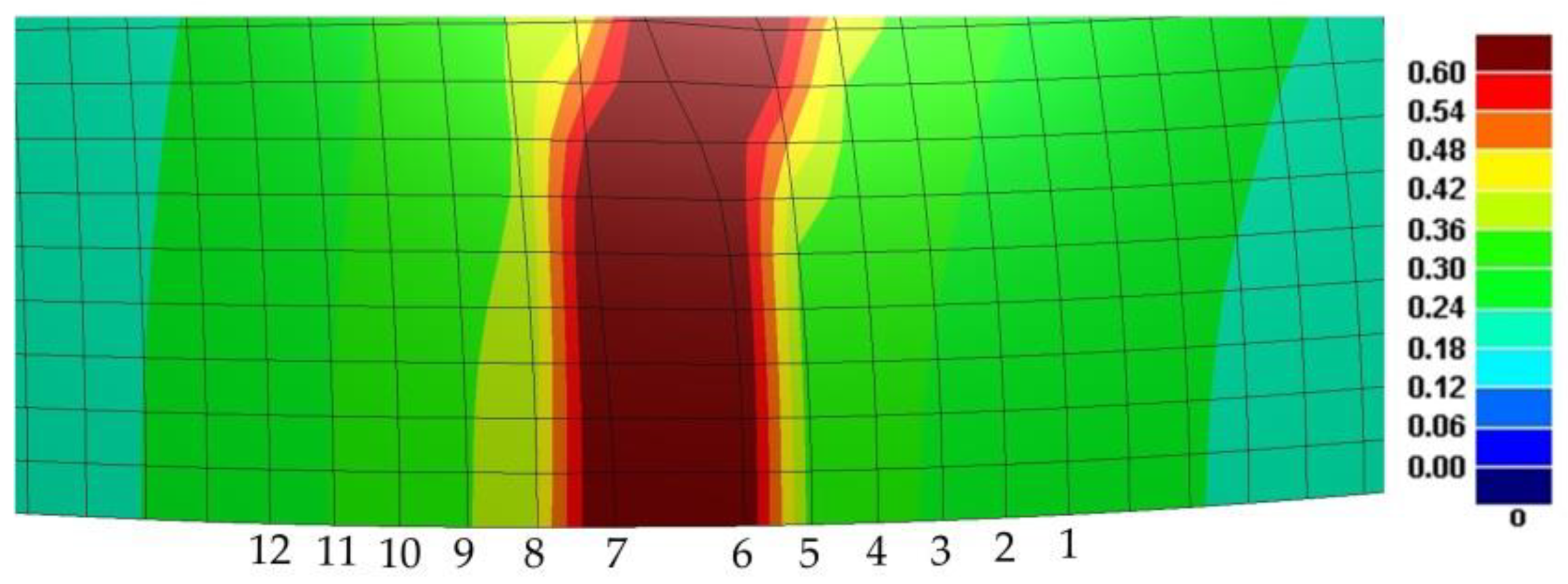
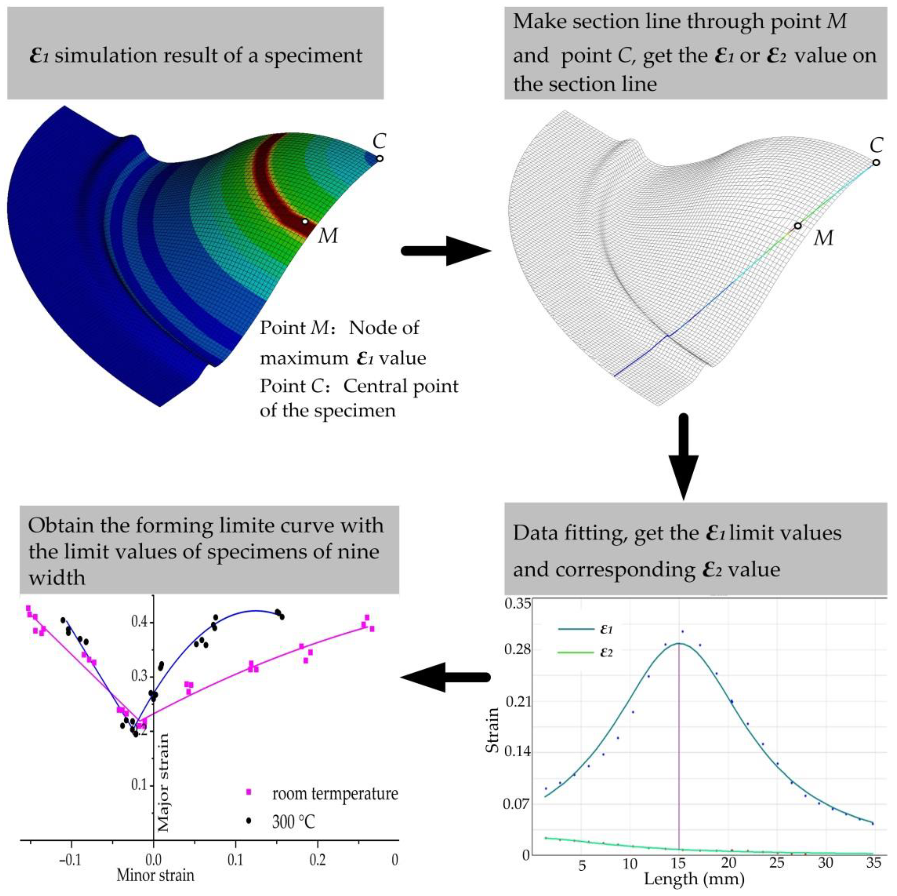
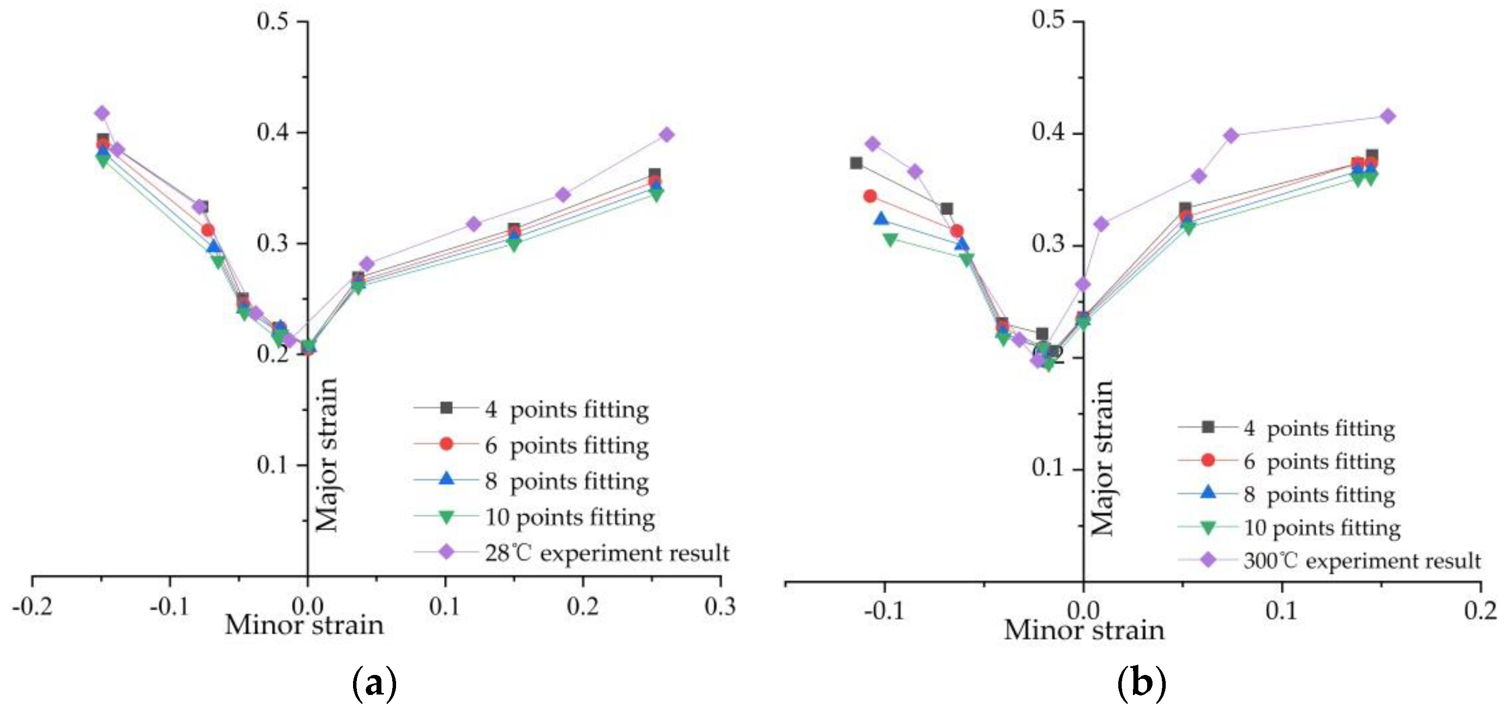
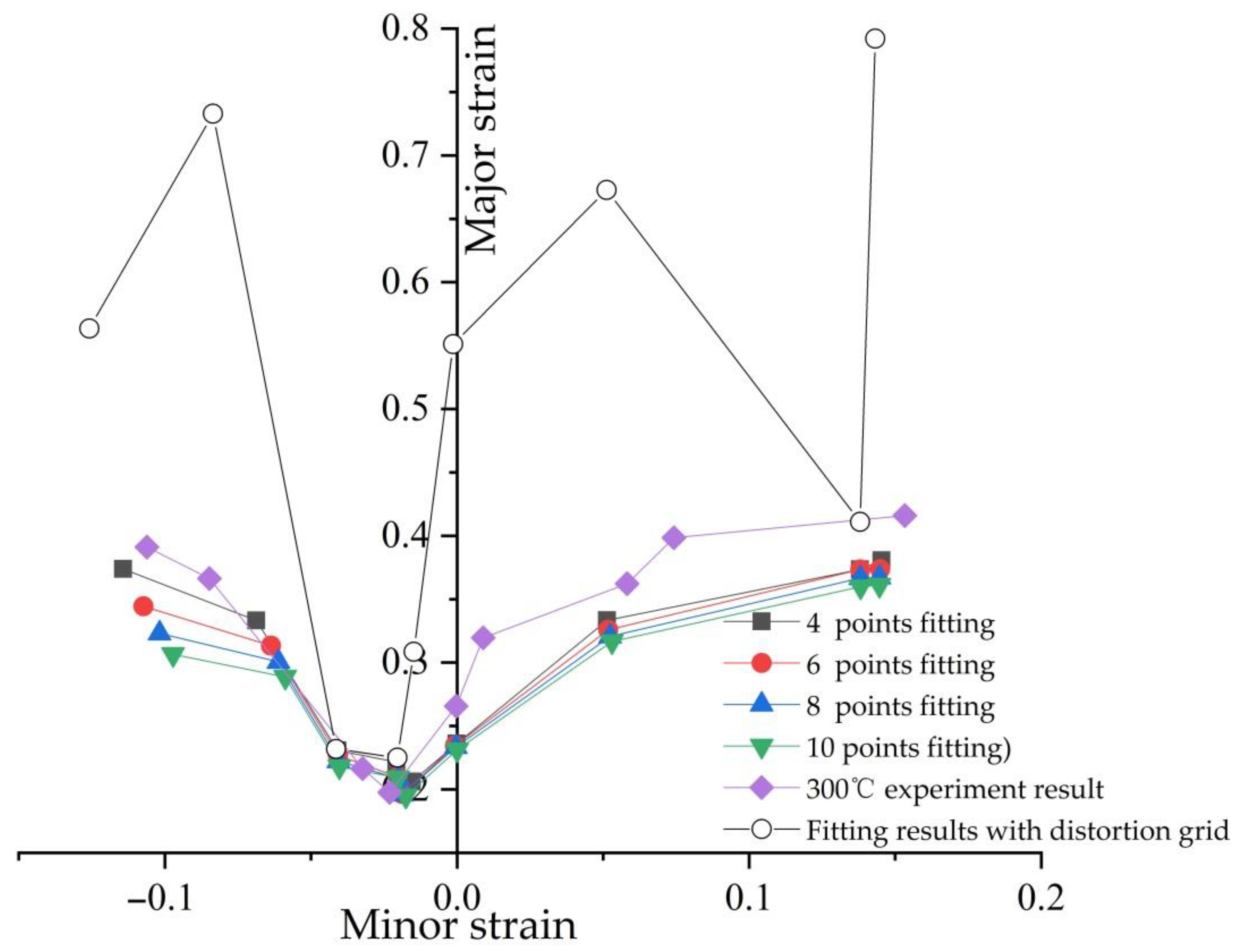
- Select the ultimate strain moment of the grid, find the point where the maximum principal strain is located, connect it with the central point of the specimen to make a cross line, and obtain the maximum principal strain and minimum principal strain of the node on each grid of the cross line, as well as the length of the arc line from each node to the central point of the specimen. The above values should then be imported into the quadratic function polynomial , where x represents the length of the arc line from the strain measurement node to the center of the specimen, and represents the value of the maximum principal strain, or . This method is adopted to select and obtain the or values of m nodes on both sides of the distorted grid, except for the No. 6 and No. 7 nodes (refer to Figure 10). The values of a total of 2 m nodes are obtained (m = 2,3,4,5…, and the number of nodes taken is symmetrically distributed on both sides of the distorted grid).
- In the smooth data area, the quadratic parabolic function of any 2 m continuous strain measurement points , , ……, , on the cross-sectional line is obtained by interpolation.
- Use to perform least squares fitting for 2 m consecutive points on the same cross-sectional line to obtain the corresponding extreme value of , which is the limit value of the major strain, and determine the value of x’ for x that corresponds with the time when the value is obtained. Apply the same method to perform quadratic function fitting for , and take the that corresponds with the value of x’ as the limit value of minor strain.
- Use the above method to calculate the forming limit values of the specimens at each width to obtain the forming limits under nine width conditions.
5. Conclusions
Author Contributions
Funding
Institutional Review Board Statement
Informed Consent Statement
Data Availability Statement
Conflicts of Interest
Abbreviations
| Abbreviations, acronyms, and symbols | |
| FLC | Forming limit curve |
| FLD | Forming limit diagram |
| PLC | Programmable logic controller |
| LED | Light-emitting diode |
| CCD | Charge-coupled device |
| ε1 | Maximum principal strain |
| ε2 | Minimum principal strain |
| m | The number of nodes |
| n | Hardening exponent |
| t | Thickness |
| DSA | Dynamic strain aging |
Appendix A

References
- Huang, F.; Chen, Q.; Ding, H.; Wang, Y.; Mou, X.; Chen, J. Automotive Steel with a High Product of Strength and Elongation used for Cold and Hot Forming Simultaneously. Materials 2021, 14, 1121. [Google Scholar] [CrossRef]
- Sun, Y.; Wang, K.; Politis, D.J.; Chen, G.; Wang, L. An experimental investigation on the ductility and post-form strength of a martensitic steel in a novel warm stamping process. J. Mater. Process. Tech. 2020, 275, 116387. [Google Scholar] [CrossRef]
- Tokita, Y.; Nakagaito, T.; Tamai, Y.; Urabe, T. Stretch formability of high strength steel sheets in warm forming. J. Mater. Process. Tech. 2017, 246, 77–84. [Google Scholar] [CrossRef]
- Paul, S.K.; Roy, S.; Sivaprasad, S.; Tarafder, S. Forming limit diagram generation from in-plane uniaxial and notch tensile test with local strain measurement through Digital Image Correlation. Phys. Mesomech. 2019, 22, 340–344. [Google Scholar] [CrossRef]
- Stoughton, T.B.; Zhu, X.H. Review of theoretical model of the strain-based FLD and their relevance to the stress-based FLD. Int. J. Plast. 2004, 20, 1463–1486. [Google Scholar] [CrossRef]
- Singh, P.K.; Sarkar, R.B.; Raj, A.; Verma, R.K. Forming limit diagram generation with reduced experiments and modeling for different grades of automotive sheet steel using CrachLab. J. Strain. Anal. Eng. 2017, 52, 298–305. [Google Scholar] [CrossRef]
- Nakazima, K.; Kikuma, T. Study on the formability of steel sheets. Yawata Tech. Rep. 1968, 264, 8517–8530. [Google Scholar]
- Marciniak, Z.; Kuczynski, K. Limit strains in the processes of stretch-forming sheet metal. Int. J. Mech. Sci. 1967, 9, 609–620. [Google Scholar] [CrossRef]
- Song, X.; Leotoing, L.; Guines, D.; Ragneau, E. Investigation of the forming limit strains at fracture of AA5086 sheets using an in-plane biaxial tensile test. Eng. Fract. Mech. 2016, 163, 130–140. [Google Scholar] [CrossRef]
- Liu, D.; Xu, G.; Chang, C. Forming limit diagram and its calculation model for DP780 high strength steel sheet at elevated temperatures. J. Plast. Eng. 2017, 24, 192–197. [Google Scholar]
- Pandre, S.; Morchhale, A.; Kotkunde, N.; Singh, S.K. Influence of processing temperature on formability of thin-rolled DP590 steel sheet. Mater. Manuf. Process. 2020, 35, 901–909. [Google Scholar] [CrossRef]
- Cai, G.; Wu, C.; Gao, Z.; Lang, L.; Alexandrov, S. Research on Al-alloy sheet forming formability during warm/hot sheet hydroforming based on elliptical warm bulging test. AIP ADV 2018, 8, 055023. [Google Scholar] [CrossRef] [Green Version]
- Chen, J.; Gong, P.; Yang, L. Forming limit evaluation for AA5182 aluminum alloy at warm temperatures based on M–K model. J. Mater. Eng. Perform. 2020, 29, 1176–1184. [Google Scholar] [CrossRef]
- Li, J.; Xie, X.; Yang, G.; Du, C.; Yang, L. Forming limit diagram determination using Digital Image Correlation: A Review; Conference Proceedings of the Society for Experimental Mechanics Series; Springer: Cham, Switzerland, 2017; pp. 59–61. [Google Scholar]
- Khoo, S.W.; Karuppanan, S.; Tan, C.S. A review of surface deformation and strain measurement using two-dimensional digital image correlation. Metrol. Meas. Syst. 2016, 23, 461–480. [Google Scholar] [CrossRef]
- Hu, H.; Liang, J.; Tang, Z.; Guo, X.; Li, L. Digital speckle based strain measurement system for forming limit diagram prediction. Opt. Laser. Eng. 2014, 55, 12–21. [Google Scholar] [CrossRef]
- Lumelskyj, D.; Rojek, J.; Banabic, D.; Lazarescu, L. Detection of strain localization in Nakazima formability test—experimental research and numerical simulation. Procedia Eng. 2017, 183, 89–94. [Google Scholar] [CrossRef]
- Bandyopadhyay, K.; Basak, S.; Prasad, K.S.; Lee, M.G.; Panda, S.K.; Lee, J. Improved formability prediction by modeling evolution of anisotropy of steel sheets. Int. J. Solids Struct. 2019, 156–157, 263–280. [Google Scholar] [CrossRef]
- Behrens, B.A.; Uhe, J.; Wester, H.; Stockburger, E. Hot forming limit curves for numerical press hardening simulation of AISI 420C. In Proceedings of the 29th International Conference on Metallurgy and Materials (Metal 2020), Conference Proceedings, Brno, Czech Republic, 20–22 May 2020; pp. 350–355. [Google Scholar]
- ISO/FDIS 12004-2:2008. Metallic Materials—Sheet and Strip—Determination of Forming-Limit Curves—Part 2: Determination of Forming-Limit Curves in the Laboratory; ISO Final Draft International Standard: Geneva, Switzerland, 2008.
- GB/T 15825.8-2008, Sheet Metal Formability and Test Methods—Part 8: Guidelines for the Determination of Forming-Limit Diagrams; The Chinese National Standard: Beijing, China, 2008.
- GB/T 24171.2-2009, Metallic Materials—Sheet and Strip—Determinations of Forming Limit Curves—Part 2: Determinations of Forming Limit Curves in Laboratory; The Chinese National Standard: Beijing, China, 2009.
- Kuril, A.A.; Janaki Ram, G.D.; Bakshi, S.R. Microstructure and mechanical properties of keyhole plasma arc welded dual phase steel. J. Mater. Process. Tech. 2019, 270, 28–36. [Google Scholar] [CrossRef]
- Pepelnjak, T.; Kayhan, E.; Kaftanoglu, B. Analysis of non-isothermal warm deep drawing of dual-phase DP600 steel. Int. J. Mater. Form. 2018, 12, 1–18. [Google Scholar] [CrossRef]
- Saxena, K.K.; Drotleff, K.; Mukhopadhyay, J. Elevated temperature forming limit strain diagrams of automotive alloys Al6014-T4 and DP600: A case study. J. Strain. Anal. Eng. 2016, 51, 459–470. [Google Scholar] [CrossRef]
- Mulford, R.A. Analysis of strengthening mechanisms in alloys by means of thermal-activation theory. Acta Mater. 1979, 27, 1115–1124. [Google Scholar] [CrossRef]
- Ghosh, A.K.; Backofen, W.A. Strain hardening and instability in biaxially streched sheets. Metall. Trans 1973, 4, 1113–1123. [Google Scholar] [CrossRef]
- Dolzhenkov, I.E. The nature of blue brittleness of steel. Met. Sci. Heat Treat. 1971, 13, 220–224. [Google Scholar] [CrossRef]
- Song, Y.; Daniel, G.D.; Rusinek, A. Constitutive models for dynamic strain aging in metals: Strain rate and temperature dependences on the flow stress. Materials 2020, 13, 1794. [Google Scholar] [CrossRef] [PubMed] [Green Version]
- Bayramin, B.; Simsir, C.; Efe, M. Dynamic strain aging in dp steels at forming relevant strain rates and temperatures. Mat. Sci. Eng. A-Struct. 2017, 704, 164–172. [Google Scholar] [CrossRef]


| Indicator | Parameter |
|---|---|
| Maximum stamping force (KN) | 600 |
| Forming speed (mm/min) | 0–750 |
| Maximum clamping force (KN) | 600 |
| Stamping stroke (mm) | 0–150 |
| Sheet material thickness range (mm) | 0.2~4.0 |
| Sheet material width range (mm) | 0~220 |
| Specimen heating temperature (°C) | Up to 900 |
| Cupping punch diameter (mm) | 100 |
Publisher’s Note: MDPI stays neutral with regard to jurisdictional claims in published maps and institutional affiliations. |
© 2021 by the authors. Licensee MDPI, Basel, Switzerland. This article is an open access article distributed under the terms and conditions of the Creative Commons Attribution (CC BY) license (https://creativecommons.org/licenses/by/4.0/).
Share and Cite
Yu, Q.; Liang, J.; Li, Q.; Li, C. Development of Measurement Equipment and Experimental and Numerical Simulation Studies for Warm Forming Limits of High-Strength Steel. Materials 2021, 14, 2373. https://doi.org/10.3390/ma14092373
Yu Q, Liang J, Li Q, Li C. Development of Measurement Equipment and Experimental and Numerical Simulation Studies for Warm Forming Limits of High-Strength Steel. Materials. 2021; 14(9):2373. https://doi.org/10.3390/ma14092373
Chicago/Turabian StyleYu, Qiang, Jin Liang, Qiu Li, and Chengyao Li. 2021. "Development of Measurement Equipment and Experimental and Numerical Simulation Studies for Warm Forming Limits of High-Strength Steel" Materials 14, no. 9: 2373. https://doi.org/10.3390/ma14092373