
Influence of Subsequently Applied Mechanical and Thermal Loads on Surfaces Ground with Mechanical Main Impact


Abstract
:1. Introduction
2. Materials and Methods
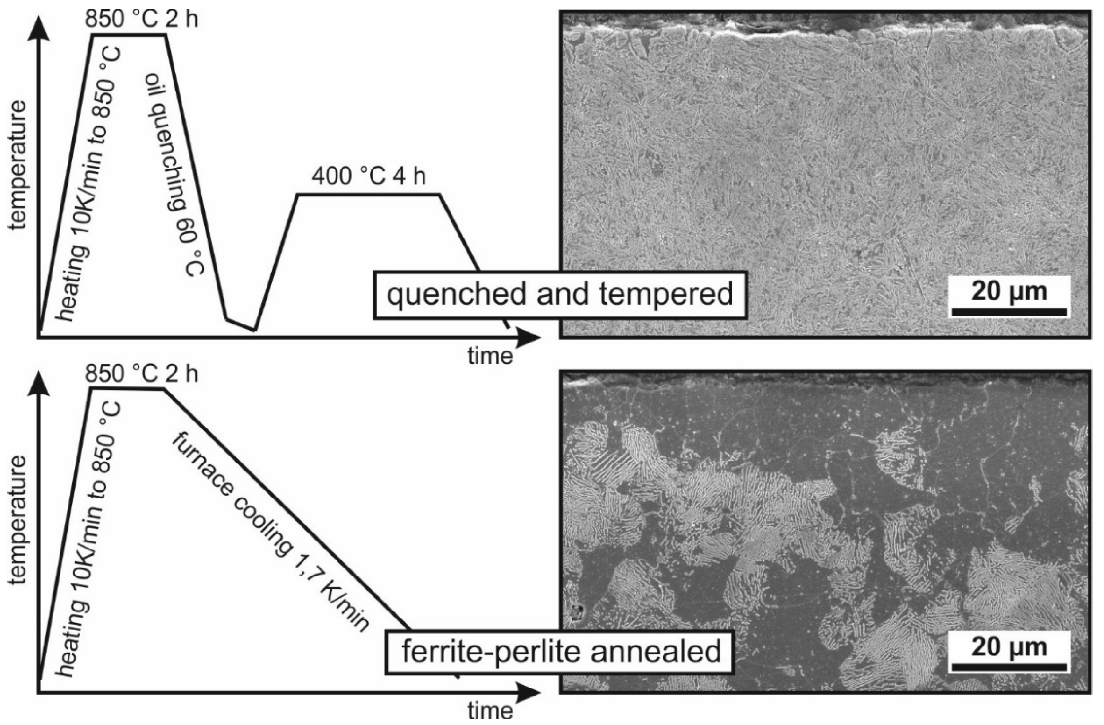
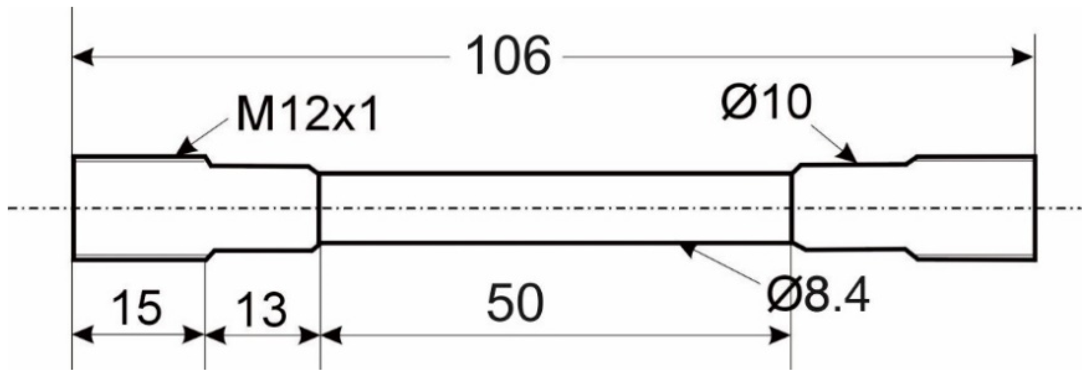
2.1. Specimens
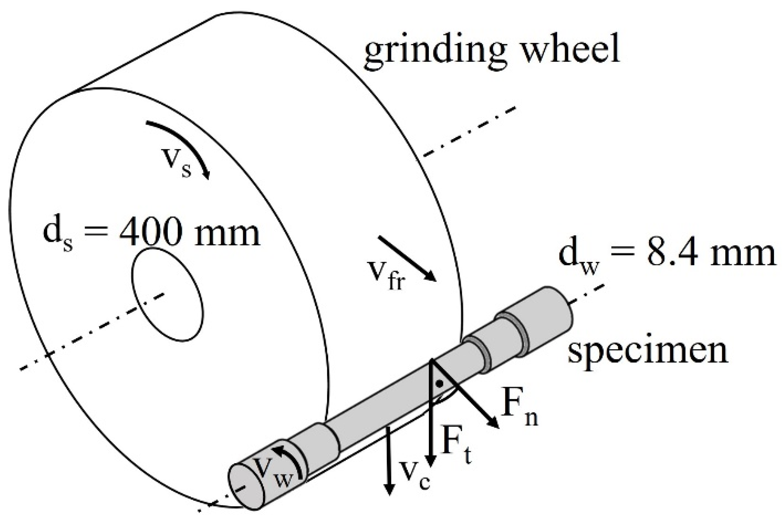
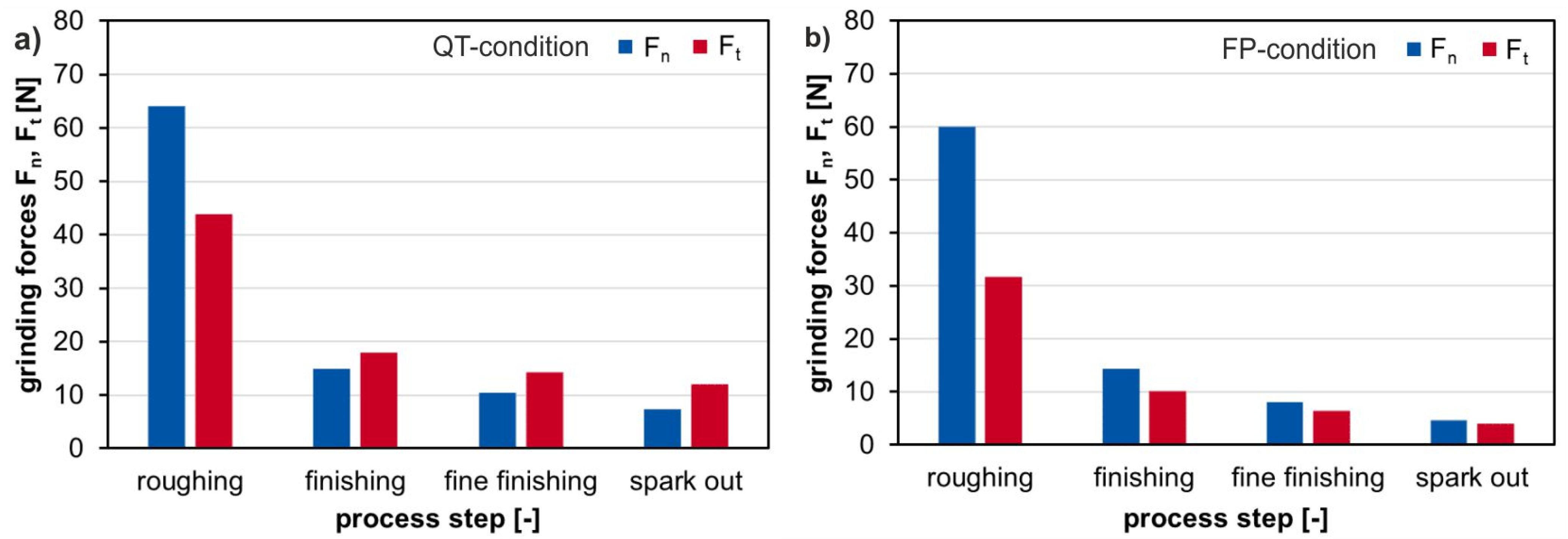
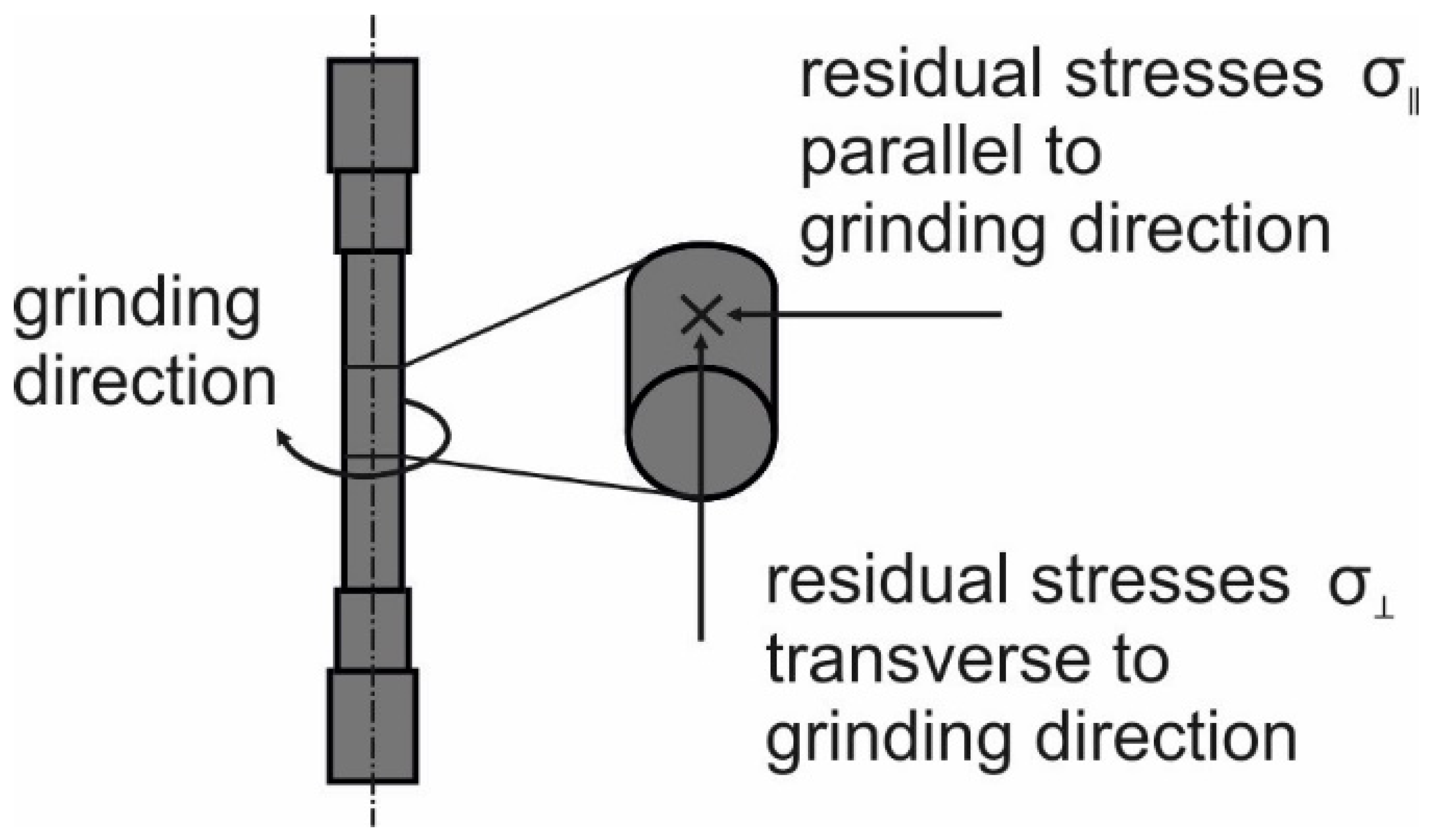
2.2. Grinding Process
2.3. Application of Defined Loads after Grinding
- A mechanical load (σmaxFP or σmaxQT).
- A sequence of an initial mechanical load (σmaxFP or σmaxQT) followed by a thermal load (1 h at 700 °C).
- A thermal load (1 h at 700 °C).
- A sequence of an initial thermal load (1 h at 700 °C) followed by a mechanical load (σmaxFP or σmaxQT).
- A simultaneous combination of the mechanical (σmaxFP or σmaxQT) and the thermal load (1 h at 700 °C).
2.4. Measurement of Surface Modifications
3. Results
3.1. Influence of Different Mechanical Loads on Grind-Strengthened Surface Layer Modifications
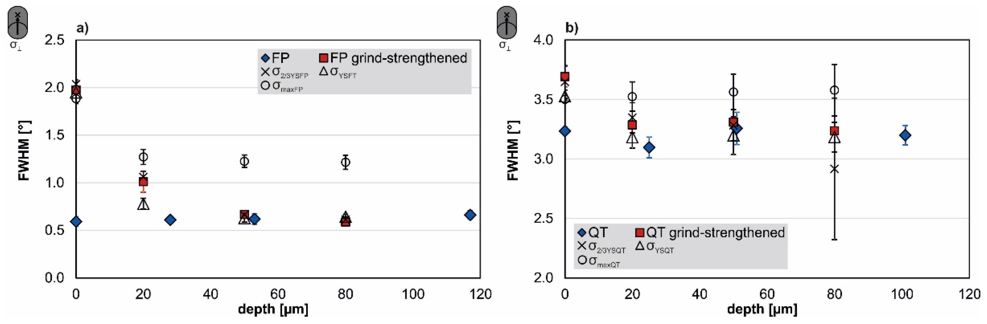
3.2. Full Width at Half Maximum Depth Profiles
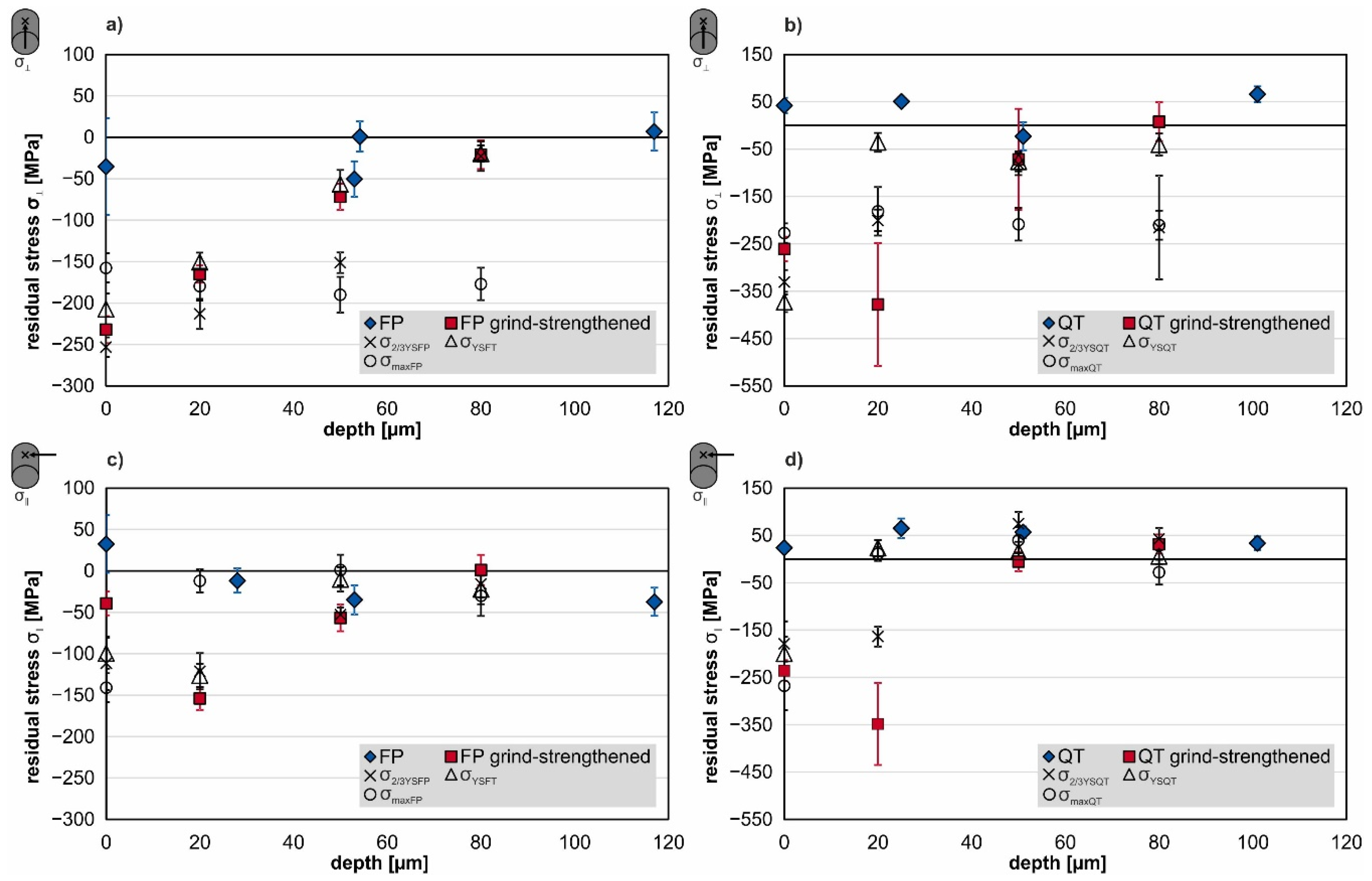
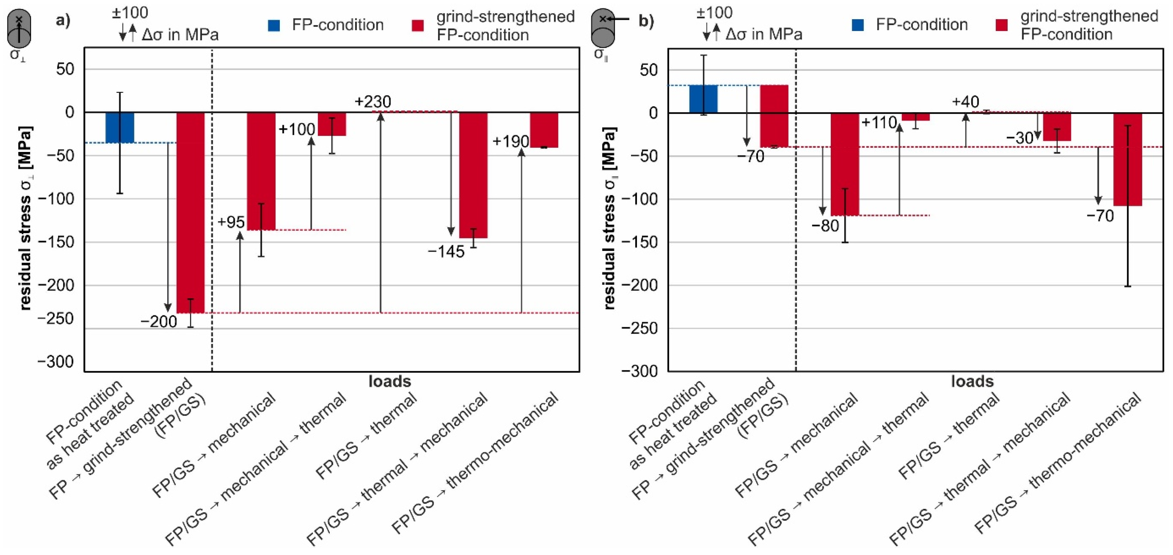
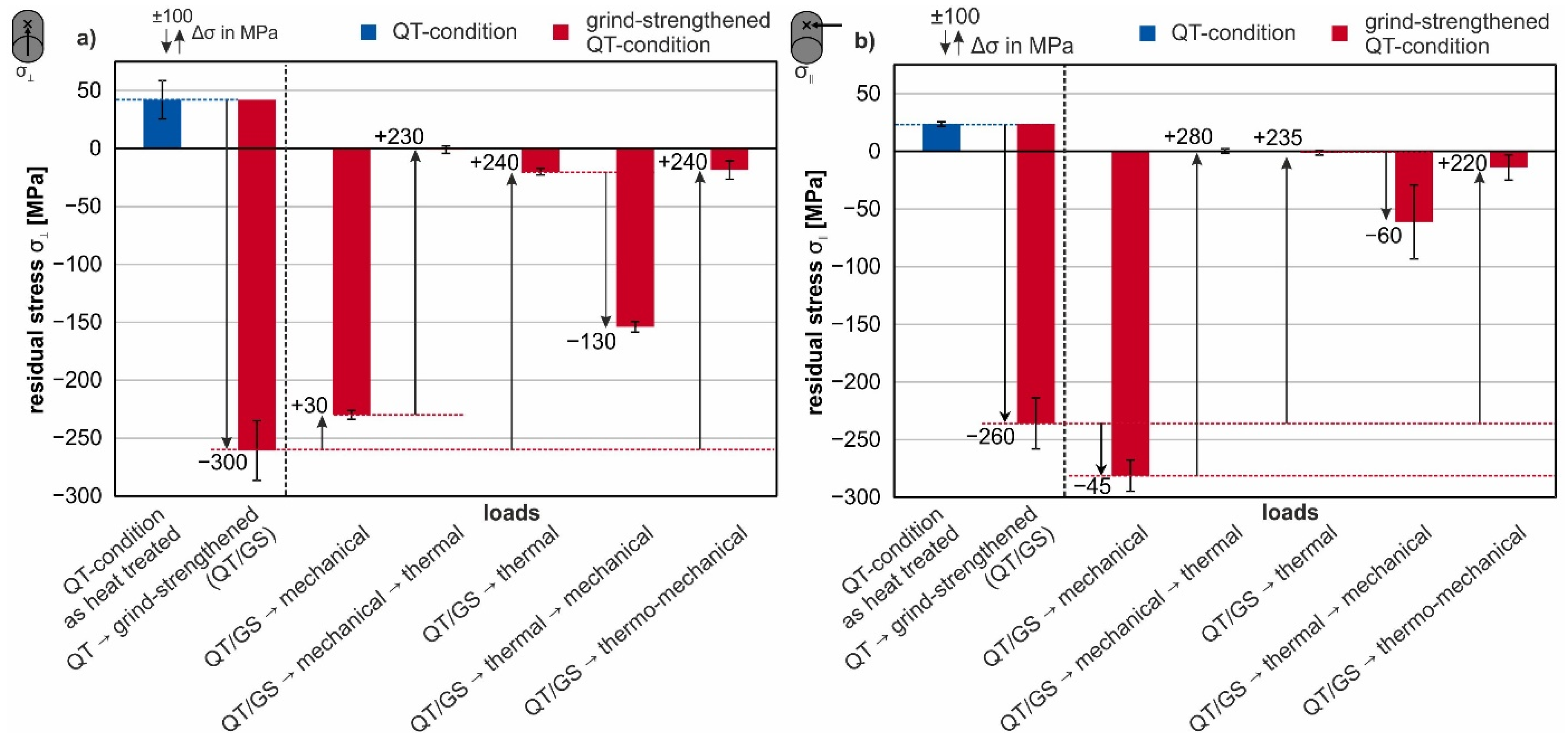
3.3. Surface Residual Stresses after Different Loads and Loading Sequences
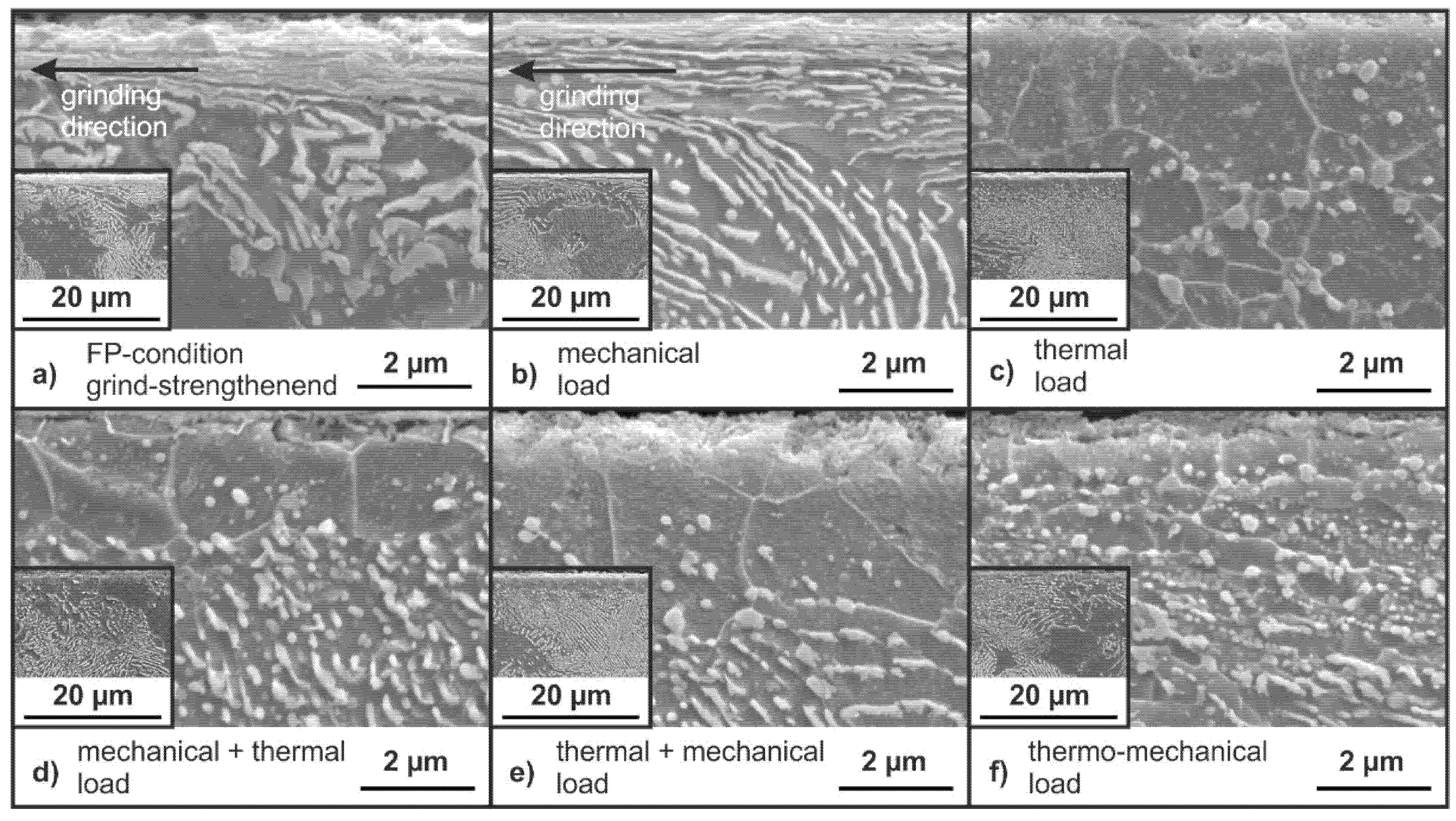
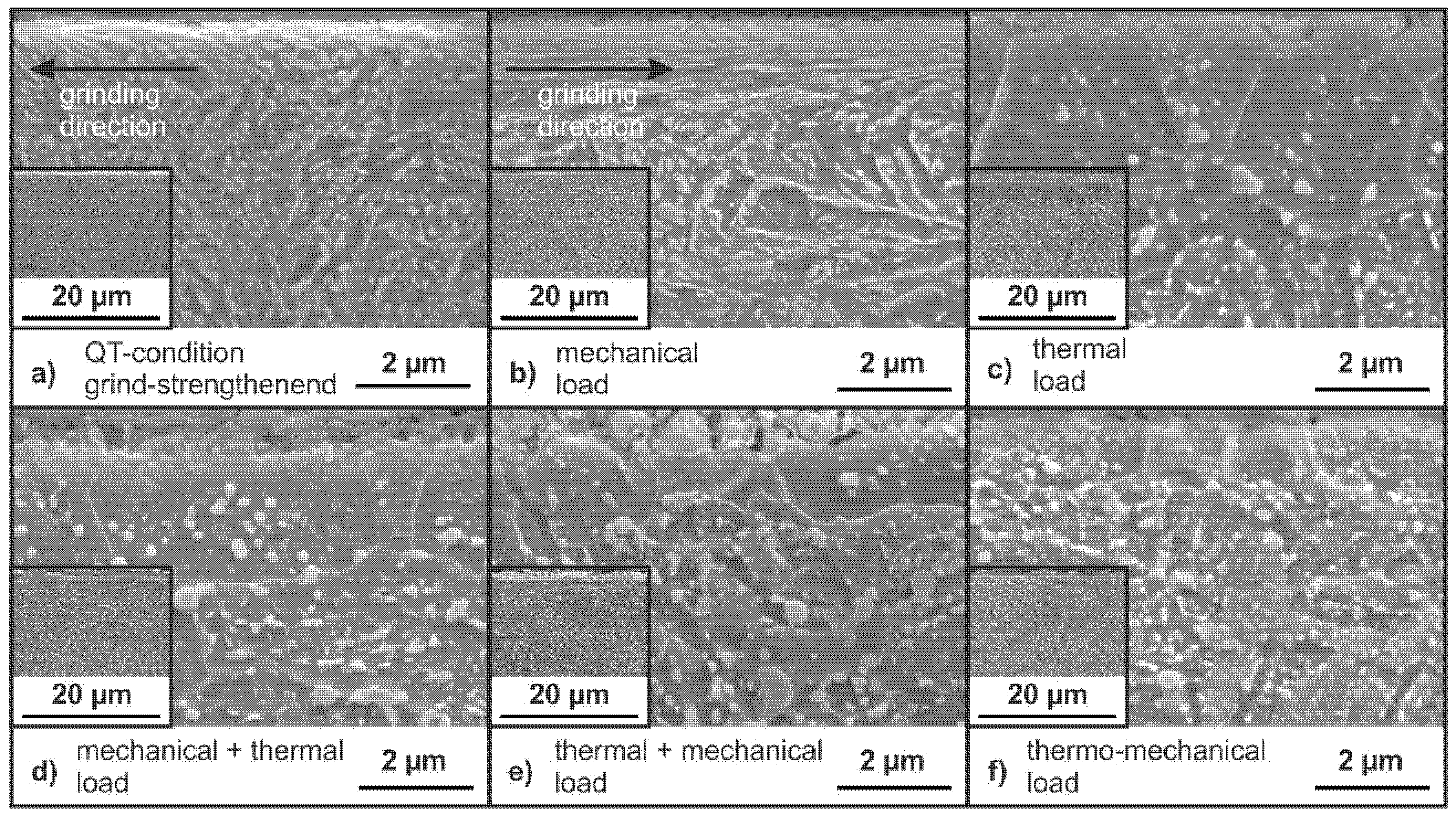
3.4. Scanning Electron Microscope Micrographs of the Ground Specimens in FP- and QT-Condition
4. Discussion
5. Conclusions
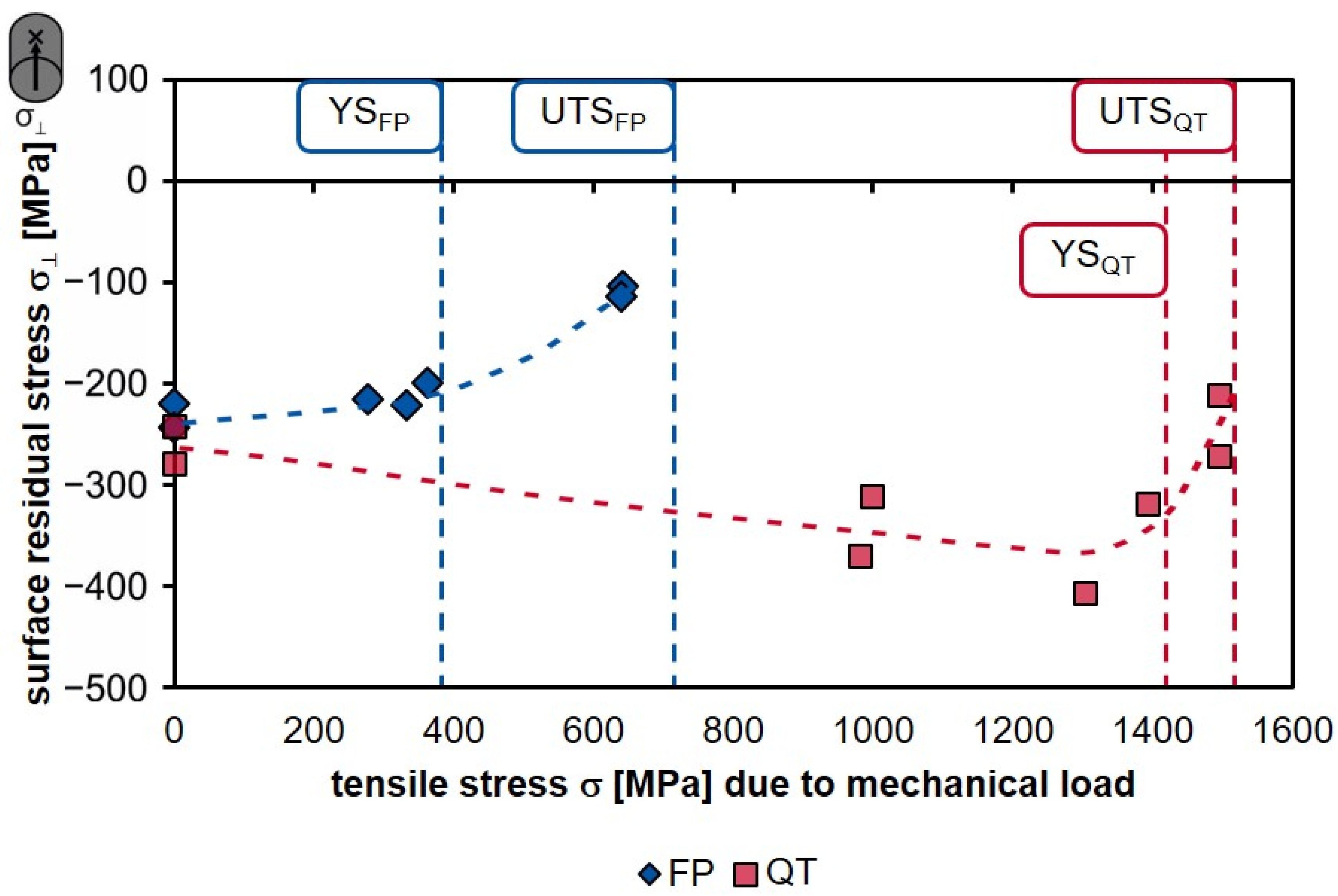
- Subjecting the ground specimens to different mechanical loads in the order of two-thirds of the respective yield strength, close to the respective yield strength, and close to the respective ultimate tensile strength confirmed that the yield strength is a critical parameter for applied mechanical loads since plastic deformation occurs when this parameter is exceeded. The results show that the residual stresses were lowered the closer the selected load was to the local yield strength.
- Subjecting the selected thermal results in a complete relaxation of the residual stresses caused by the grinding process due to recrystallization and resulting in the same microstructure at the surface.
- Subjecting a sequence of an initial mechanical load (σmaxFP or σmaxQT) followed by a thermal load (1 h at 700 °C) to the ground specimens results in decreased residual stress at the surface.
- Subjecting a sequence of an initial thermal load (1 h at 700 °C) followed by a mechanical load (σmaxFP or σmaxQT) to the ground specimens results in a similar residual stress state for both investigated material conditions and similar microstructures near the surface.
- Subjecting a simultaneous combination of the mechanical (σmaxFP or σmaxQT) and the thermal load (1 h at 700 °C) to the ground specimens result in only a small amount of residual stress due to the tempering process. The dominant mechanism is dynamic recrystallization according to Ehle et al. [8].
Author Contributions
Funding
Data Availability Statement
Acknowledgments
Conflicts of Interest
References
- Wagner, K. Beanspruchungsangepasste Kaltmassivumformwerkzeuge Durch Lokal Optimierte Werkzeugoberflächen. Ph.D. Thesis, Friedrich-Alexander-Universität, Erlangen-Nürnberg, Germany, 2011. [Google Scholar]
- Smith, S.; Melkote, S.N.; Lara-Curzio, E.; Watkins, T.R.; Allard, L.; Riester, L. Effect of surface integrity of hard turned AISI 52100 steel on fatigue performance. Mater. Sci. Eng. A 2007, 459, 337–346. [Google Scholar] [CrossRef]
- Brinksmeier, E.; Cammett, J.T.; König, W.; Leskovar, P.; Peters, J.; Tönshoff, H.K. Residual Stresses—Measurement and Causes in Machining Processes. CIRP Ann. 1982, 31, 491–510. [Google Scholar] [CrossRef]
- Brinksmeier, E.; Reese, S.; Klink, A.; Langenhorst, L.; Lübben, T.; Meinke, M.; Meyer, D.; Riemer, O.; Sölter, J. Underlying Mechanisms for Developing Process Signatures in Manufacturing. Nanomanuf. Metrol. 2018, 1, 193–208. [Google Scholar] [CrossRef] [Green Version]
- Brinksmeier, E.; Meyer, D.; Heinzel, C.; Lübben, T.; Sölter, J.; Langenhorst, L.; Frerichs, F.; Kämmler, J.; Kohls, E.; Kuschel, S. Process Signatures—The Missing Link to Predict Surface Integrity in Machining. Procedia CIRP 2018, 71, 3–10. [Google Scholar] [CrossRef]
- Brinksmeier, E.; Klocke, F.; Lucca, D.A.; Sölter, J.; Meyer, D. Process Signatures—A New Approach to Solve the Inverse Surface Integrity Problem in Machining Processes. Procedia CIRP 2014, 13, 429–434. [Google Scholar] [CrossRef] [Green Version]
- Sealy, M.P.; Liu, Z.Y.; Guo, Y.B.; Liu, Z.Q. Energy based process signature for surface integrity in hard milling. J. Mater. Process. Technol. 2016, 238, 284–289. [Google Scholar] [CrossRef]
- Ehle, L.C.; Strunk, R.; Borchers, F.; Schwedt, A.; Clausen, B.; Mayer, J. Influence of process chains with thermal, mechanical and thermo-mechanical impact on the surface modifications of a grind-strengthened 42CrMo4 steel. Procedia CIRP 2020, 87, 426–431. [Google Scholar] [CrossRef]
- Hiroshi EDA; Kozo KISHI; Satoshi HASHIMOTO. The Formation Mechanism of Ground White Layers. Bull. JSME 1981, 24, 743–747. [Google Scholar] [CrossRef] [Green Version]
- Guo, Y.B.; Warren, A.W.; Hashimoto, F. The basic relationships between residual stress, white layer, and fatigue life of hard turned and ground surfaces in rolling contact. CIRP J. Manuf. Sci. Technol. 2010, 2, 129–134. [Google Scholar] [CrossRef]
- Hoffmann, J.E.; Löhe, D. Einfluss von Makroeigenspannungen auf das Ermüdungsverhalten von glatten und gekerbten Proben aus gehärtetem Ck 45. HTM Z. Werkst. Waermebeh. Fert. 2002, 57, 79–85. [Google Scholar]
- Wohlfahrt, H. Shot peening and fatigue of materials. In Proceedings of 9th International Conference on Shot Peening 1; Niku-Lari, A., Ed.; Pergamon Press: Oxford, UK, 1982; pp. 675–694. [Google Scholar]
- Löhe, D.; Lang, K.-H. Residual Stresses and Fatigue Behavior. In Handbook of Residual Stress and Deformation of Steel; Totten, G.E., Howes, M.A.H., Inoue, T., Eds.; ASM International: Almere, The Netherlands, 2002; ISBN 0871707292. [Google Scholar]
- Holzapfel, H.; Schulze, V.; Vöhringer, O.; Macherauch, E. Residual stress relaxation in an AISI 4140 steel due to quasistatic and cyclic loading at higher temperatures. Mater. Sci. Eng. A 1998, 248, 9–18. [Google Scholar] [CrossRef]
- Vöhringer, O. Auswirkungen der mechanischen Oberflächenbehandlungen bei thermischer und mechanischer Beanspruchung. In Mechanische Oberflächenbehandlungen: Grundlagen, Bauteileigenschaften, Anwendungen; Wohlfahrt, H., Krull, P., Eds.; Wiley-VCH: Weinheim, Germany, 2000; pp. 29–53. ISBN 9783527301188. [Google Scholar]
- Hirsch, T.; Vöhringer, O.; Macherauch, E. Der Einfluss von Zug- bzw. Druckverformungen auf die Oberflächeneigenspannungen von gestrahltem AlCu5Mg2. HTM Haerterei-Tech. Mitt. 1988, 43, 16–19. [Google Scholar]
- Madariaga, A.; Esnaola, J.A.; Arrazola, P.J.; Ruiz-Hervias, J.; Muñoz, P.; Ostolaza, K. Stability of machining induced residual stresses in Inconel 718 under quasi-static loading at room temperature. Mater. Sci. Eng. A 2015, 620, 129–139. [Google Scholar] [CrossRef]
- Holzapfel, H.; Schulze, V.; Vöhringer, O.; Macherauch, E. Stability and Relaxation Behaviour of Shot Peening Induced Residual Stresses in AISI 4140 during Bending Fatigue. In Proceedings of the 6th International Conference on Shot Peening, San Francisco, CA, USA, 2–5 September 1996; pp. 413–423. [Google Scholar]
- Hirsch, T.; Vöhringer, O.; Macherauch, E. Der thermische Abbau von Strahleigenspannungen bei TiAl6V4. HTM Haerterei-Tech. Mitt. 1983, 38, 229–232. [Google Scholar]
- Schlaak, U.; Hirsch, T.; Mayr, P. Röntgenographische in-situ-Messungen zum thermischen Eigenspannungsabbau bei erhöhter Temperatur. HTM 1988, 43, 92–101. [Google Scholar] [CrossRef]
- Schulze, V.; Burgahn, F.; Vöhringer, O.; Macherauch, E. Zum thermischen Abbau von Kugelstrahl-Eigenspannungen bei vergütetem 42 CrMo 4. Mater. Werkst. 1993, 24, 258–267. [Google Scholar] [CrossRef]
- Roth, M. Die thermische Stabilität von Eigenspannungen in kugelgestrahlten Oberflächen. Mater. Werkst. 1987, 18, 225–228. [Google Scholar] [CrossRef]
- Heinzel, C.; Bleil, N. The Use of the Size Effect in Grinding for Work-hardening. CIRP Ann. 2007, 56, 327–330. [Google Scholar] [CrossRef]
- Raabe, D. Recovery and Recrystallization: Phenomena, Physics, Models, Simulation. In Physical Metallurgy; Elsevier: Amsterdam, The Netherlands, 2014; pp. 2291–2397. ISBN 9780444537706. [Google Scholar]
- Hauk, V.; Behnken, H. Structural and Residual Stress Analysis by Nondestructive Methods. Evaluation, Application, Assessment; Elsevier: Amsterdam, The Netherlands, 1997; ISBN 9781281059949. [Google Scholar]
- Müller, I. Vergleich Ortsaufgelöster Zerstörungsfreier Methoden zur Plastizitätsuntersuchung. Ph.D. Theis, Rheinische Friedrich–Wilhelms–Universität Bonn, Bonn, Germany, 2006. [Google Scholar]
- Warren, A.W. X-ray Diffraction; Dover Publications Inc.: New York, NY, USA, 1990. [Google Scholar]
- Lepper, K. Entwicklung Einer Auslegungsmethodik für Ermüdungsfeste Stahlbauteile unter Berücksichtigung von Fertigungsabhängigen Werkstoffzuständen; Karlsruher Institut für Technologie: Karlsruhe, Germany, 2016. [Google Scholar]
- Nikitin, I.; Scholtes, B.; Maier, H.J.; Altenberger, I. High temperature fatigue behavior and residual stress stability of laser-shock peened and deep rolled austenitic steel AISI 304. Scr. Mater. 2004, 50, 1345–1350. [Google Scholar] [CrossRef]
- Brinksmeier, E.; Heinzel, C.; Bleil, N. Superfinishing and grind-strengthening with elastic bonding system. J. Mater. Process. Technol. 2009, 209, 6117–6123. [Google Scholar] [CrossRef]
- Hoffmann, J.; Starker, P.; Macherauch, E. Bearbeitungseigenspannungen. In Eigenspannungen und Lastspannungen; Hauk, V., Macherauch, E., Eds.; Carl Hanser Verlag: München, Germany; Wien, Austria, 1982; pp. 84–91. [Google Scholar]

| Workpiece | Grinding Wheel | ||
|---|---|---|---|
| material | AISI4140 (42CrMo4) | specification | 9A60H16V |
| diameter | dw = 8.4 mm | diameter | ds = 400 mm |
| tangential feed speed | vw = 1.8 m/s (down-hill grinding) | width | bw = 50 mm |
| wheel speed | vs = 13.8 m/s | ||
| dressing parameters | process parameters | ||
| depth of cut in dressing | ae,d = 20 µm | depth of cut | ae = 150 µm/40 µm/10 µm |
| overlap ratio | Ud = 3 | radial feed speed | vfr = 2.0 mm/min/0.4 mm/min/0.2 mm/min |
| speed ratio | qd = 0.6 | cutting speed | vc = 12 m/s |
| spark out time | ts = 4 s | ||
| Material Condition | ||
|---|---|---|
| FP | QT | |
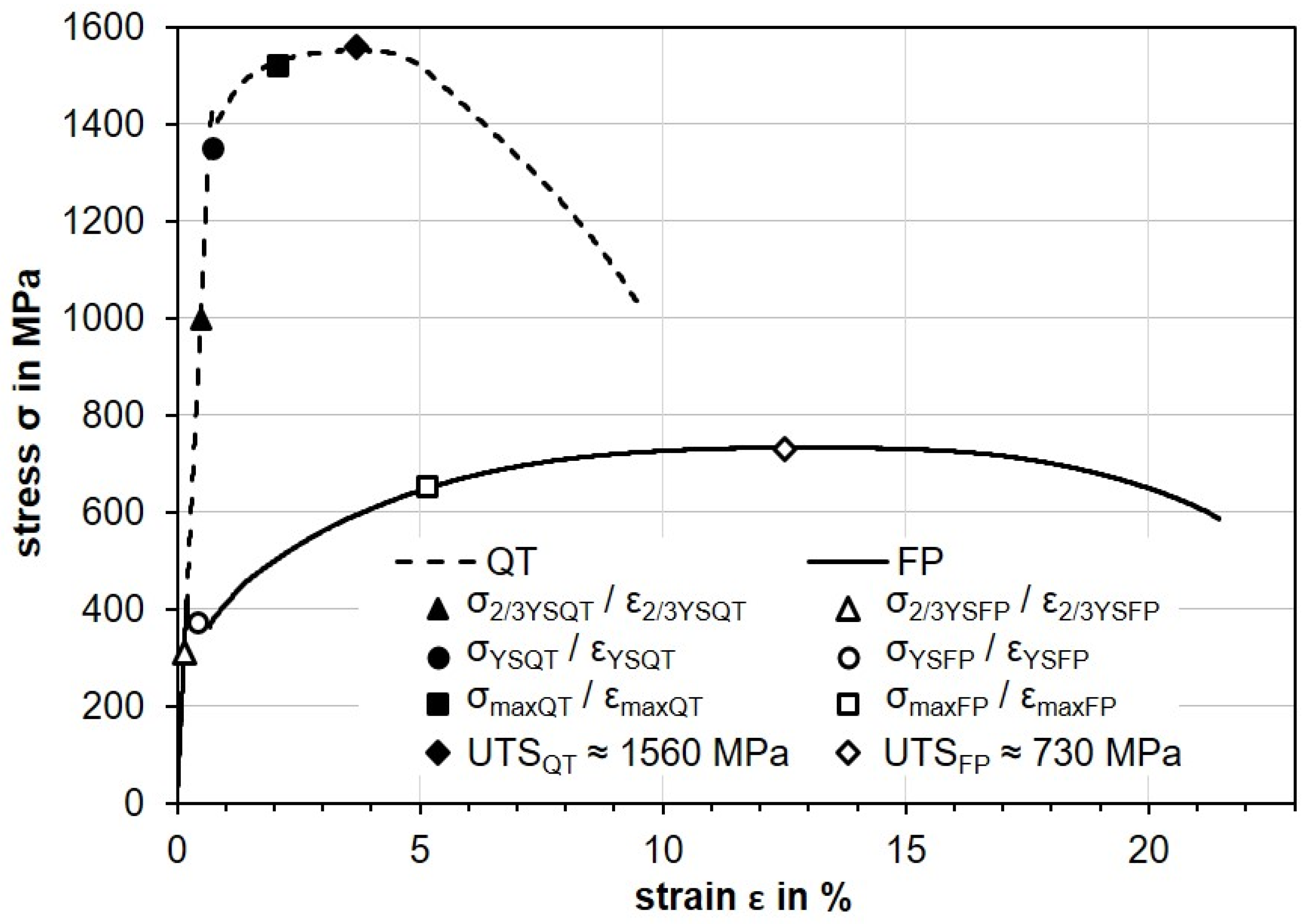
| yield strength (YS) | 380 MPa (YSFP) | 1420 MPa (YSQT) |
| ultimate tensile strength (UTS) | 730 MPa (UTSFP) | 1560 MPa (UTSQT) |
| mechanical loads | tensile test up to | |
| σ2/3YSFP ≈ 300 MPa (ε2/3YSFP ≈ 2/3 YSFP) | σ2/3YSQT ≈ 990 MPa (ε2/3YSQT ≈ 2/3 YSQT) | |
| σYSFP ≈ 370 MPa (εYSFP ≈ YSFP) | σYSQT ≈ 1350 MPa (εYSQT ≈ YSQT) | |
| σmaxFP ≈ 650 MPa (εmaxFP = 5%) | σmaxQT ≈ 1520 MPa (εmaxQT = 2%) | |
| thermal load | annealing for 1 h at 700 °C | |
| thermo-mechanical load | tensile test at 700 °C up to | |
| σmaxFP ≈ 650 MPa (εmaxFP = 5%) | σmaxQT ≈ 1520 MPa (εmaxQT = 2%) | |
Publisher’s Note: MDPI stays neutral with regard to jurisdictional claims in published maps and institutional affiliations. |
© 2021 by the authors. Licensee MDPI, Basel, Switzerland. This article is an open access article distributed under the terms and conditions of the Creative Commons Attribution (CC BY) license (https://creativecommons.org/licenses/by/4.0/).
Share and Cite
Strunk, R.; Borchers, F.; Clausen, B.; Heinzel, C. Influence of Subsequently Applied Mechanical and Thermal Loads on Surfaces Ground with Mechanical Main Impact. Materials 2021, 14, 2386. https://doi.org/10.3390/ma14092386
Strunk R, Borchers F, Clausen B, Heinzel C. Influence of Subsequently Applied Mechanical and Thermal Loads on Surfaces Ground with Mechanical Main Impact. Materials. 2021; 14(9):2386. https://doi.org/10.3390/ma14092386
Chicago/Turabian StyleStrunk, Rebecca, Florian Borchers, Brigitte Clausen, and Carsten Heinzel. 2021. "Influence of Subsequently Applied Mechanical and Thermal Loads on Surfaces Ground with Mechanical Main Impact" Materials 14, no. 9: 2386. https://doi.org/10.3390/ma14092386
APA StyleStrunk, R., Borchers, F., Clausen, B., & Heinzel, C. (2021). Influence of Subsequently Applied Mechanical and Thermal Loads on Surfaces Ground with Mechanical Main Impact. Materials, 14(9), 2386. https://doi.org/10.3390/ma14092386