
Enhanced Hydrofobicity of Polymers for Personal Protective Equipment Achieved by Chemical and Physical Modification

 , , and
Abstract
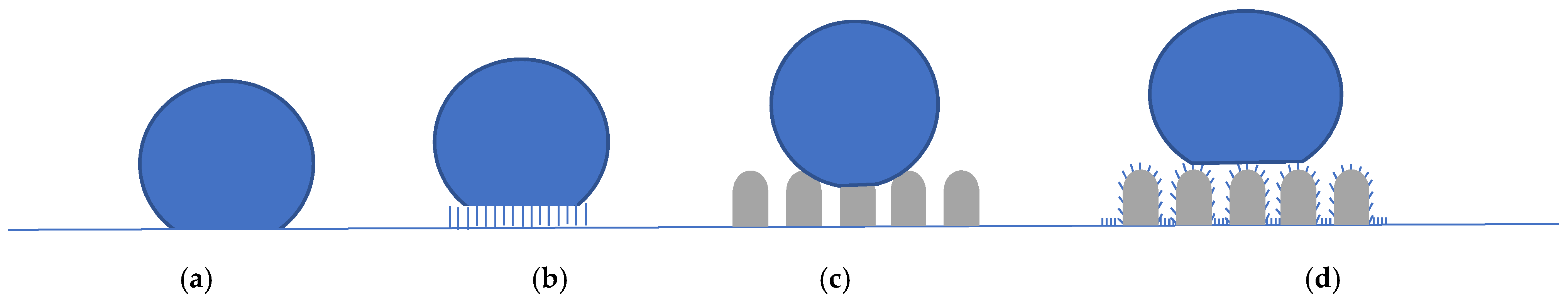
:1. Introduction
2. Materials and Methods
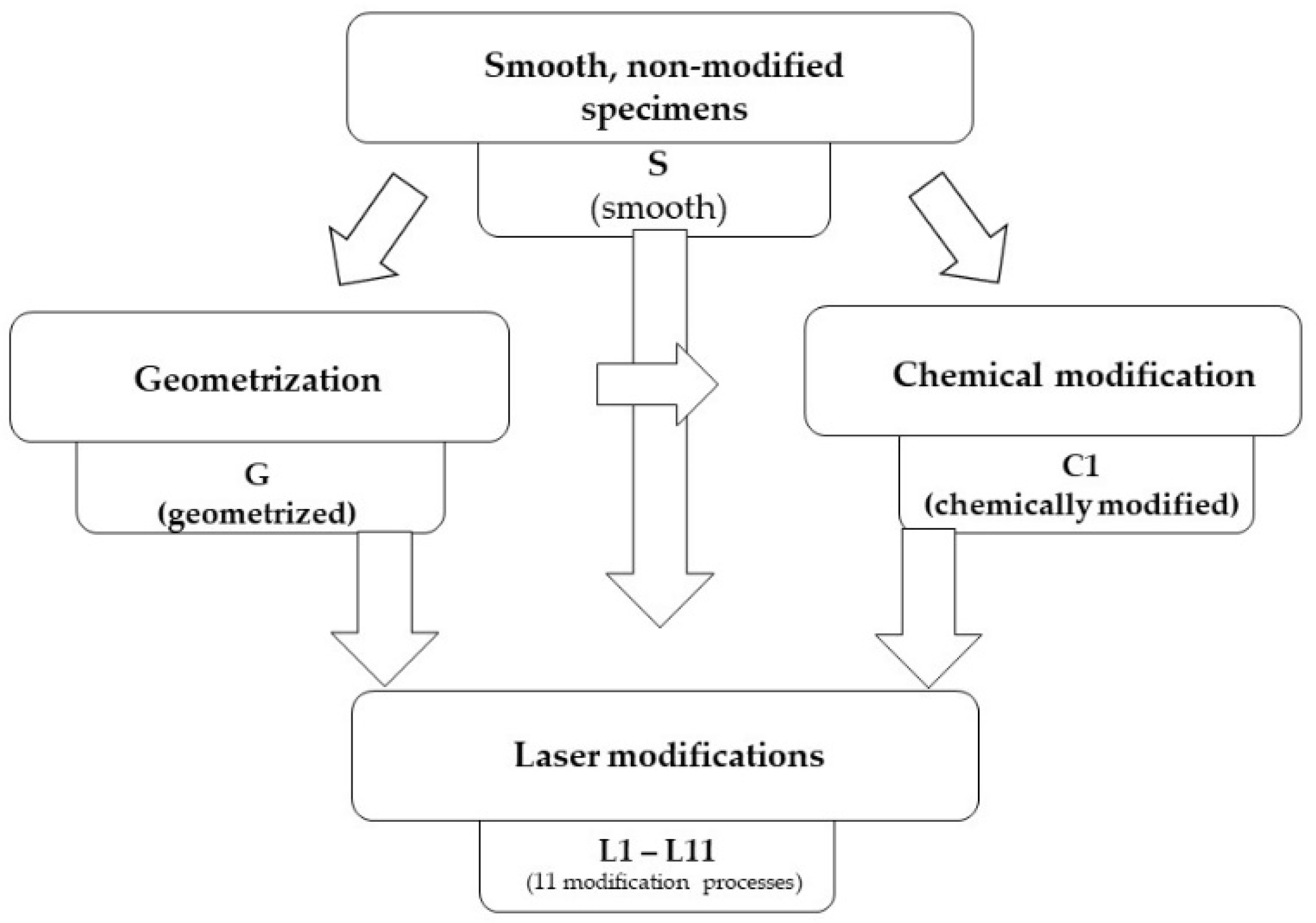
2.1. Preparation of Samples
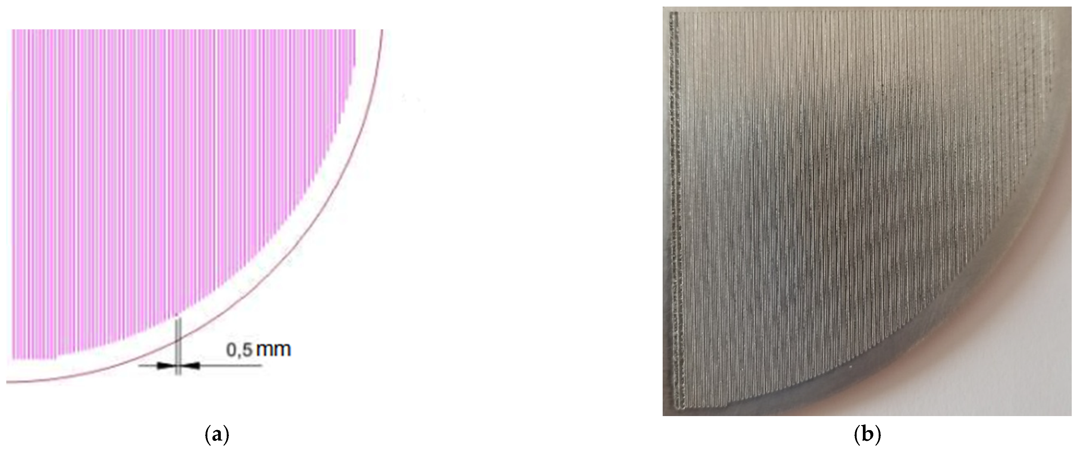
2.2. Geometrisation
2.3. Chemical Modification
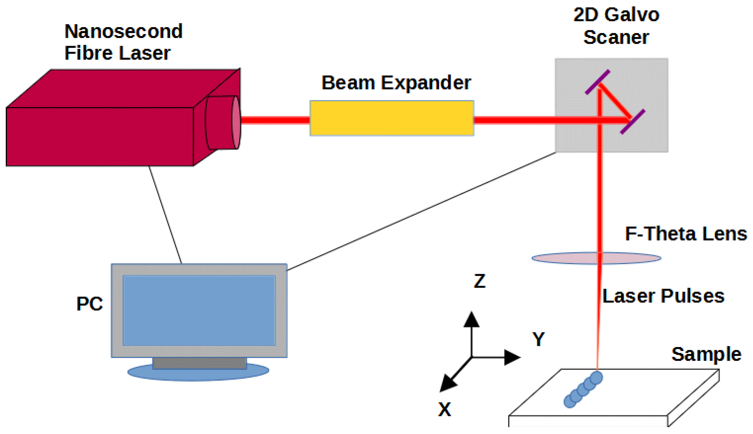
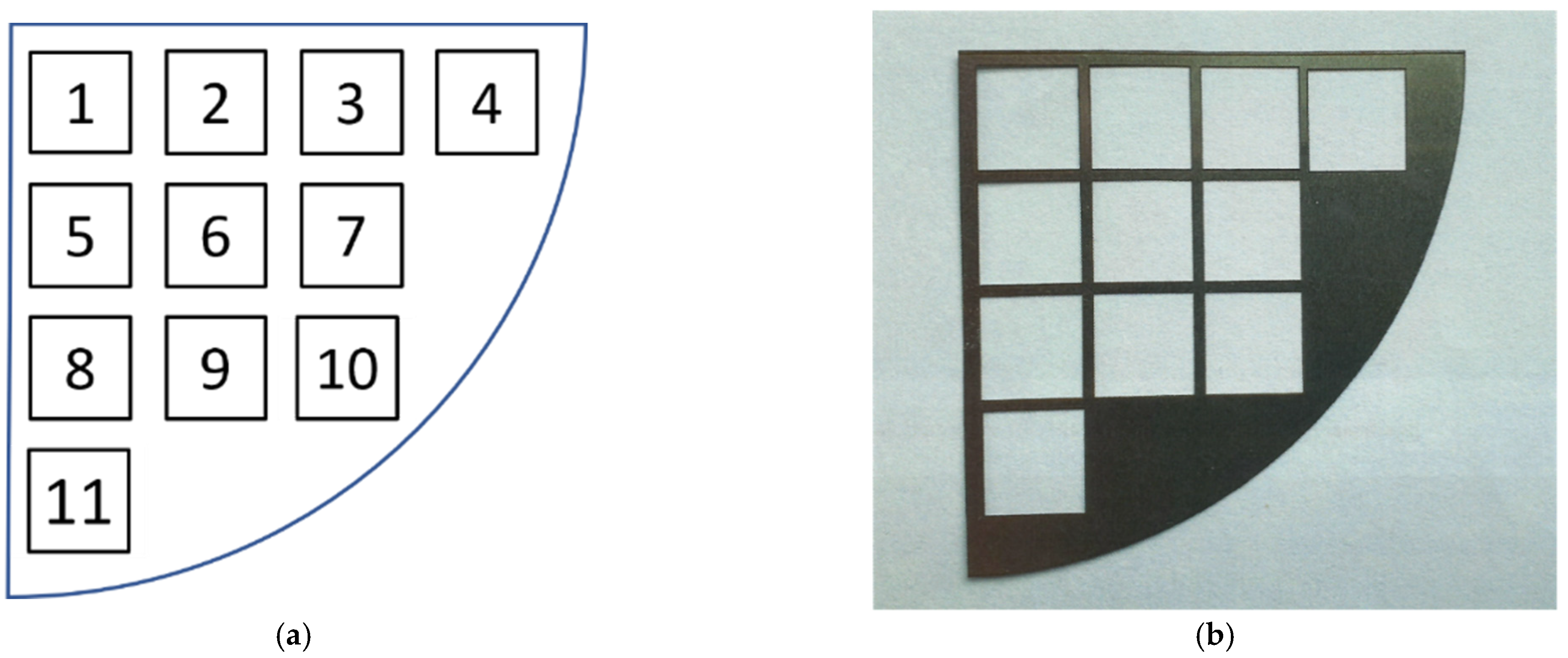
2.4. Laser Modification
2.5. Surface Morphology Evaluation with Scanning Electron Microscopy (SEM)
2.6. Spectra Making with the Fourier Transform Infrared (FT-IR) Method
2.7. Contact Angle Measurements
3. Results
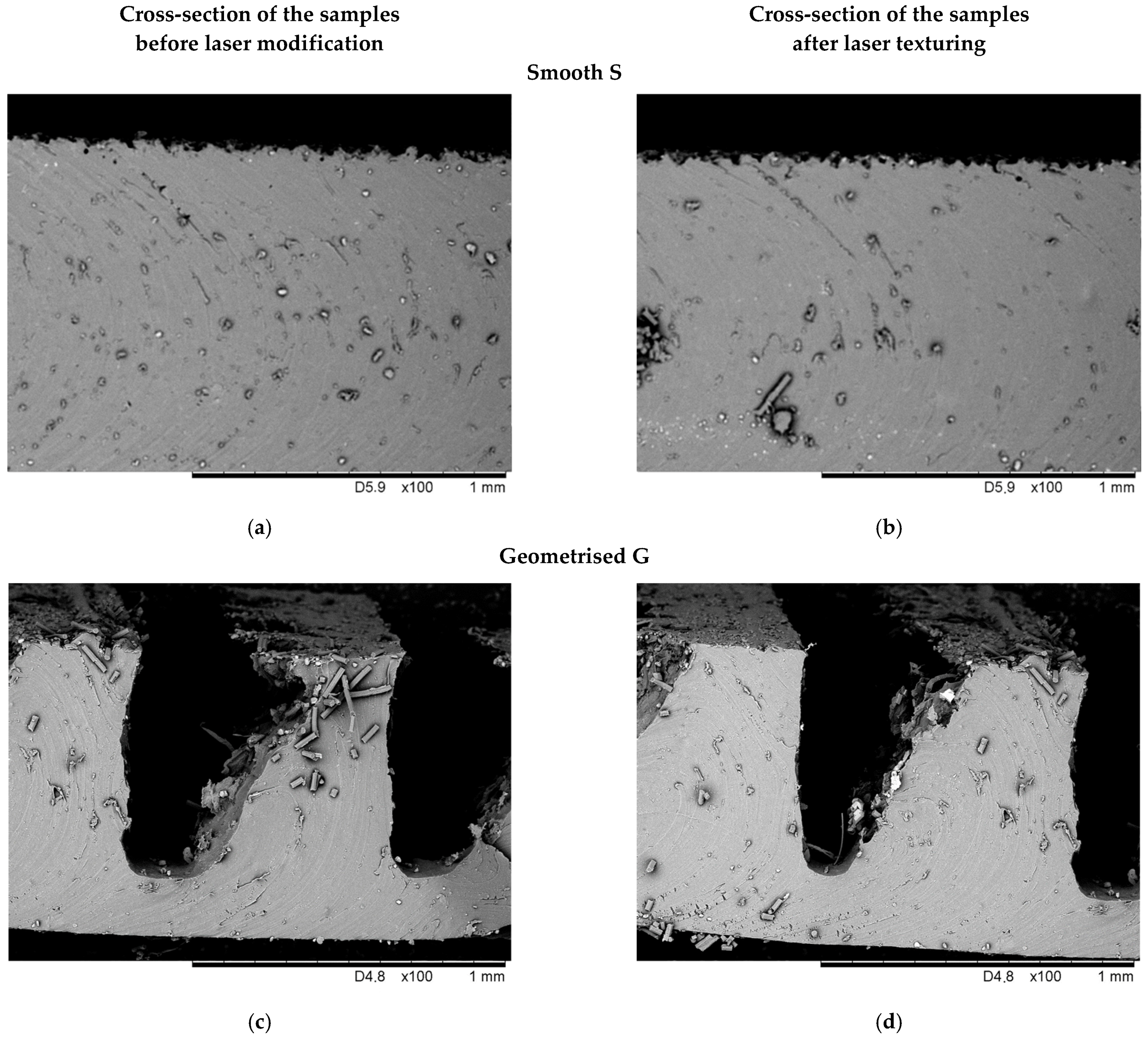
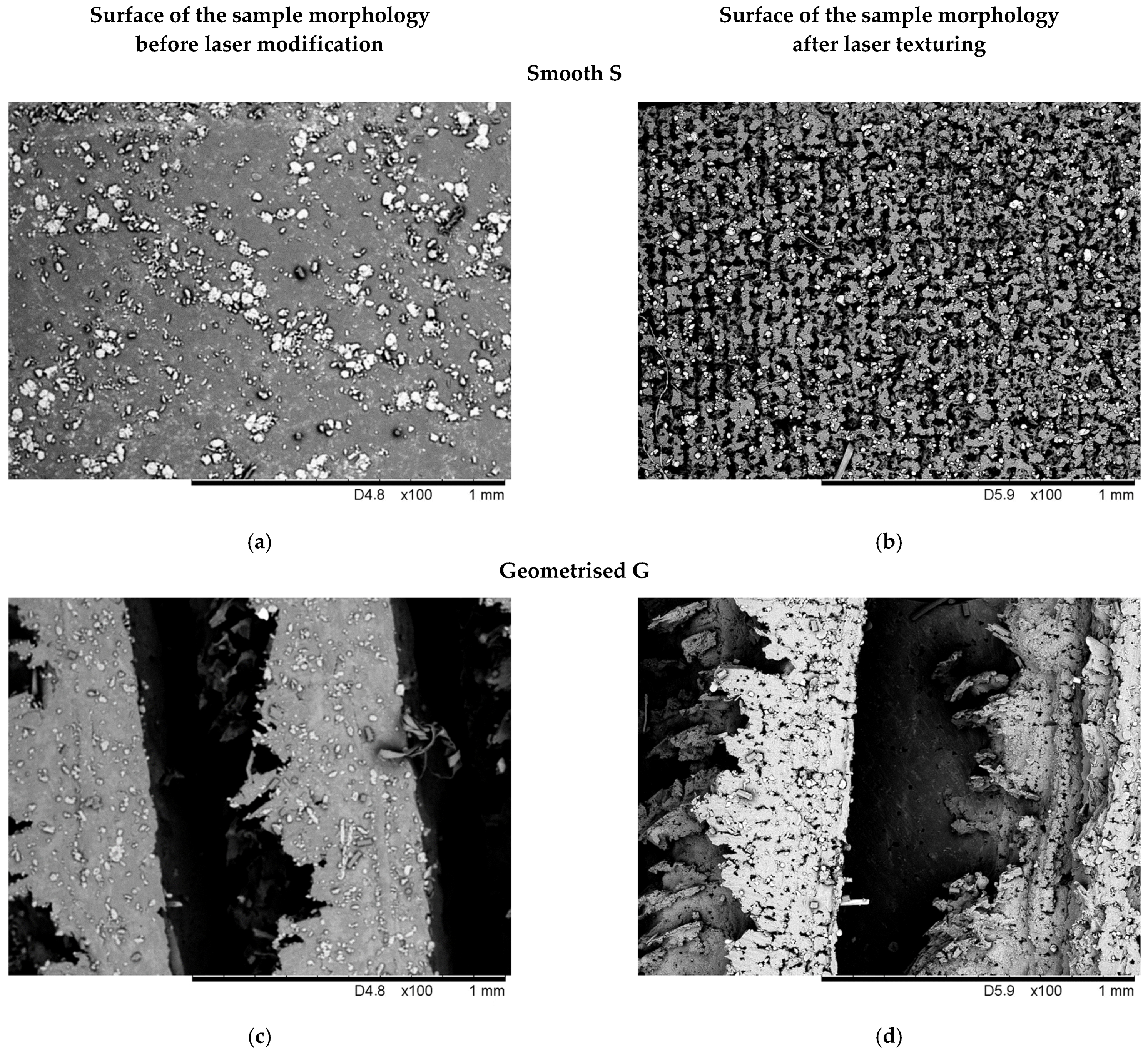
3.1. Evaluation of the Surface Morphology with SEM
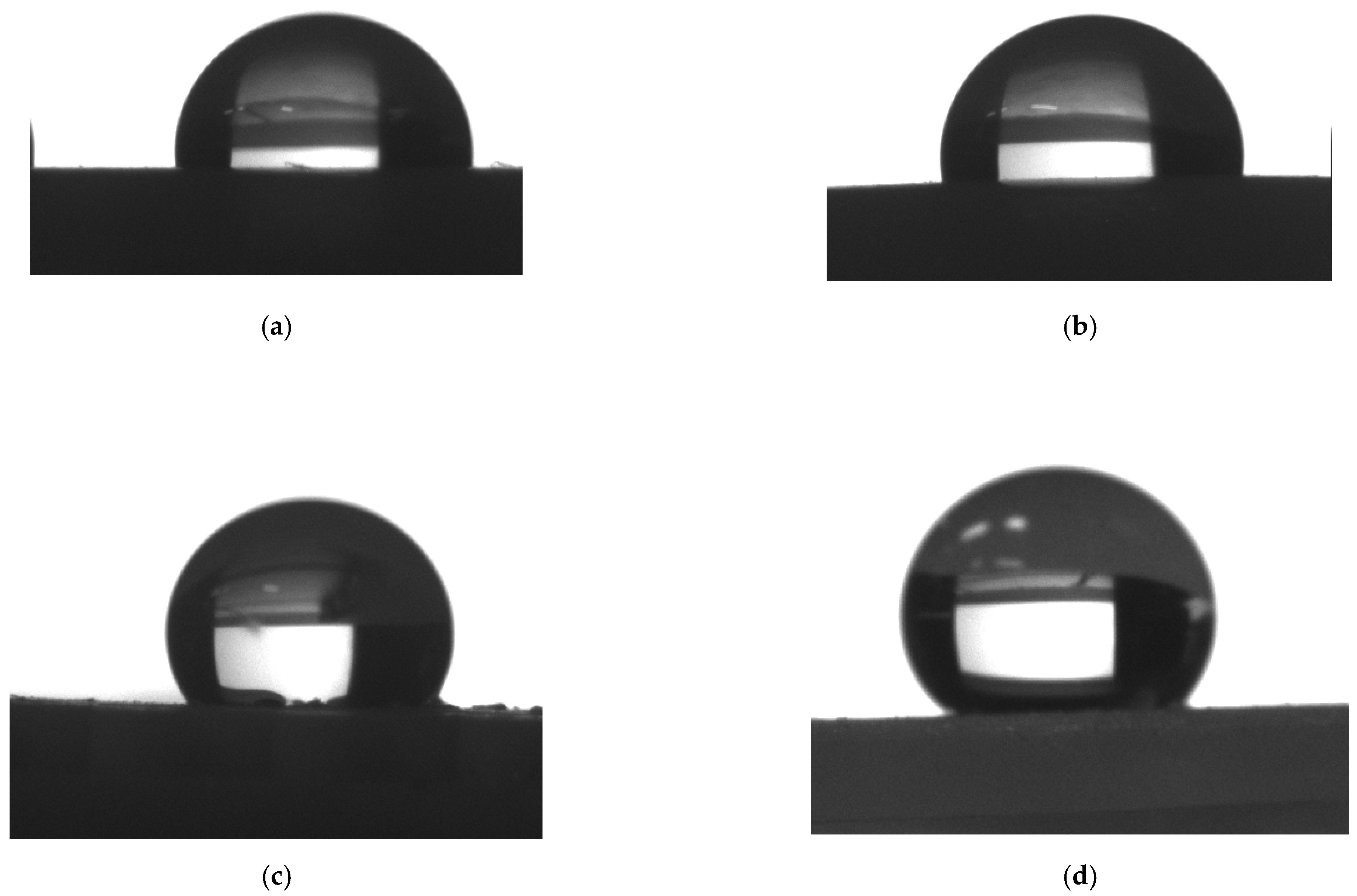
3.2. Contact Angle Measurements
3.3. Analysis of the Vulcanisates Structure Using FT-IR Spectroscopy
4. Discussion
5. Conclusions
Author Contributions
Funding
Institutional Review Board Statement
Informed Consent Statement
Data Availability Statement
Acknowledgments
Conflicts of Interest
References
- Li, H.; Li, L.; Huang, R.; Tan, C.; Yang, J.; Xia, H.; Chen, B.; Song, X. The effect of surface texturing on the laser-induced wetting behaviour of AlSi5 alloy on Ti6Al4V alloy. Appl. Surf. Sci. 2021, 566, 150630. [Google Scholar] [CrossRef]
- Riveiro, A.; Maçon, A.L.B.; Del Val, J.; Comesaña, R.; Pou, J. Laser Surface Texturing of Polymers for Biomedical Applications. Front. Phys. 2018, 6, 16. [Google Scholar] [CrossRef]
- Pawlak, R.; Tomczyk, M.; Walczak, M.; Mizeraczyk, J.; Tański, M.; Garasz, K. Selected problems in IR and UV laser micromachining of Si and GaAs in submillimeter scale. Microelectron. Eng. 2016, 151, 47–52. [Google Scholar] [CrossRef]
- Wu, X.; Yang, F.; Gan, J.; Zhao, W.; Wu, Y. A flower-like waterborne coating with self-cleaning, self-repairing properties for superhydrophobic applications. J. Mater. Res. Technol. 2021, 14, 1820–1829. [Google Scholar] [CrossRef]
- Sarkın, A.S.; Ekren, N.; Sağlam, Ş. A review of anti-reflection and self-cleaning coatings on photovoltaic panels. Sol. Energy 2020, 199, 63–73. [Google Scholar] [CrossRef]
- Wang, N.; Xiong, D.; Deng, Y.; Shi, Y.; Wang, K. Mechanically Robust Superhydrophobic Steel Surface with Anti-Icing, UV-Durability, and Corrosion Resistance Properties. ACS Appl. Mater. Interfaces 2015, 7, 6260–6272. [Google Scholar] [CrossRef] [PubMed]
- Yao, W.; Liang, W.; Huang, G.; Jiang, B.; Atrens, A.; Pan, F. Superhydrophobic coatings for corrosion protection of magnesium alloys. J. Mater. Sci. Technol. 2020, 52, 100–118. [Google Scholar] [CrossRef]
- Fu, K.; Lu, C.; Liu, Y.; Zhang, H.; Zhang, B.; Zhang, H.; Zhou, F.; Zhang, Q.; Zhu, B. Mechanically robust, self-healing superhydrophobic anti-icing coatings based on a novel fluorinated polyurethane synthesized by a two-step thiol click reaction. Chem. Eng. J. 2021, 404, 127110. [Google Scholar] [CrossRef]
- Shen, Y.; Wu, X.; Tao, J.; Zhu, C.; Lai, Y.; Chen, Z. Icephobic materials: Fundamentals, performance evaluation, and applications. Prog. Mater. Sci. 2019, 103, 509–557. [Google Scholar] [CrossRef]
- Wang, N.; Tang, L.; Cai, Y.; Tong, W.; Xiong, D. Scalable superhydrophobic coating with controllable wettability and investigations of its drag reduction. Colloids Surf. A Physicochem. Eng. Asp. 2018, 555, 290–295. [Google Scholar] [CrossRef]
- Barthlott, W.; Neinhuis, C. Purity of the sacred lotus, or escape from contamination in biological surfaces. Planta 1997, 202, 1–8. [Google Scholar] [CrossRef]
- Solga, A.; Cerman, Z.; Striffler, B.F.; Spaeth, M.; Barthlott, W. The dream of staying clean: Lotus and biomimetic surfaces. Bioinspir. Biomim. 2007, 2, S126–S134. [Google Scholar] [CrossRef]
- Si, Y.; Dong, Z.; Jiang, L. Bioinspired Designs of Superhydrophobic and Superhydrophilic Materials. ACS Cent. Sci. 2018, 4, 1102–1112. [Google Scholar] [CrossRef]
- Li, S.; Huang, J.; Chen, Z.; Chen, G.; Lai, Y. A review on special wettability textiles: Theoretical models, fabrication technologies and multifunctional applications. J. Mater. Chem. A 2017, 5, 31–55. [Google Scholar] [CrossRef] [Green Version]
- Zhang, X.; Shi, F.; Niu, J.; Jiang, Y.; Wang, Z. Superhydrophobic surfaces: From structural control to functional application. J. Mater. Chem. 2008, 18, 621–633. [Google Scholar] [CrossRef]
- Patankar, N.A. Transition between Superhydrophobic States on Rough Surfaces. Langmuir 2004, 20, 7097–7102. [Google Scholar] [CrossRef] [PubMed]
- Si, Y.; Zhu, H.; Chen, L.; Jiang, T.; Guo, Z. A multifunctional transparent superhydrophobic gel nanocoating with self-healing properties. Chem. Commun. 2015, 51, 16794–16797. [Google Scholar] [CrossRef] [PubMed]
- Wei, D.; Wang, J.; Liu, Y.; Wang, D.; Li, S.; Wang, H. Controllable superhydrophobic surfaces with tunable adhesion on Mg alloys by a simple etching method and its corrosion inhibition performance. Chem. Eng. J. 2021, 404, 126444. [Google Scholar] [CrossRef]
- Wei, X.; Zhao, B.; Li, X.-M.; Wang, Z.; He, B.-Q.; He, T.; Jiang, B. CF4 plasma surface modification of asymmetric hydrophilic polyethersulfone membranes for direct contact membrane distillation. J. Membr. Sci. 2012, 407–408, 164–175. [Google Scholar] [CrossRef]
- Guo, Z.; Liu, W.; Su, B.-L. Superhydrophobic surfaces: From natural to biomimetic to functional. J. Colloid Interface Sci. 2011, 353, 335–355. [Google Scholar] [CrossRef]
- Nishiyama, H.; Nishii, J.; Mizoshiri, M.; Hirata, Y. Microlens arrays of high-refractive-index glass fabricated by femtosecond laser lithography. Appl. Surf. Sci. 2009, 255, 9750–9753. [Google Scholar] [CrossRef]
- Gao, S.-H.; Gao, L.-H.; Zhou, K.-S. Super-hydrophobicity and oleophobicity of silicone rubber modified by CF4 radio frequency plasma. Appl. Surf. Sci. 2011, 257, 4945–4950. [Google Scholar] [CrossRef]
- Khorasani, M.; MoemenBellah, S.; Mirzadeh, H.; Sadatnia, B. Effect of surface charge and hydrophobicity of polyurethanes and silicone rubbers on L929 cells response. Colloids Surf. B Biointerfaces 2006, 51, 112–119. [Google Scholar] [CrossRef]
- Huang, S.; Zhang, Y.; Wang, Z.; Chen, F. Superhydrophobic micro-tube fabricated via one-step plasma polymerization for lossless droplet transfer. Surf. Coat. Technol. 2021, 421, 127272. [Google Scholar] [CrossRef]
- Li, Y.; Luong, D.X.; Zhang, J.; Tarkunde, Y.R.; Kittrell, C.; Sargunaraj, F.; Ji, Y.; Arnusch, C.J.; Tour, J.M. Laser-Induced Graphene in Controlled Atmospheres: From Superhydrophilic to Superhydrophobic Surfaces. Adv. Mater. 2017, 29, 1700496. [Google Scholar] [CrossRef]
- Tong, W.; Cui, L.; Qiu, R.; Yan, C.; Liu, Y.; Wang, N.; Xiong, D. Laser textured dimple-patterns to govern the surface wettability of superhydrophobic aluminum plates. J. Mater. Sci. Technol. 2021, 89, 59–67. [Google Scholar] [CrossRef]
- Ovsianikov, A.; Ostendorf, A.; Chichkov, B. Three-dimensional photofabrication with femtosecond lasers for applications in photonics and biomedicine. Appl. Surf. Sci. 2007, 253, 6599–6602. [Google Scholar] [CrossRef]
- Cardoso, M.; Tribuzi, V.; Balogh, D.; Misoguti, L.; Mendonça, C. Laser microstructuring for fabricating superhydrophobic polymeric surfaces. Appl. Surf. Sci. 2011, 257, 3281–3284. [Google Scholar] [CrossRef]
- Siciński, M.; Korzeniewska, E.; Tomczyk, M.; Pawlak, R.; Bieliński, D.; Gozdek, T.; Kałuzińska, K.; Walczak, M. Laser-Textured Rubbers with Carbon Nanotube Fillers. Polymers 2018, 10, 1091. [Google Scholar] [CrossRef] [PubMed] [Green Version]
- Chen, L.; Wang, X.; Yang, T.; Ping, H.; Bennett, P.; Zheng, Z.; Yang, Q.; Perrie, W.; Edwardson, S.; Dearden, G.; et al. Superhydrophobic micro-nano structures on silicone rubber by nanosecond laser processing. J. Phys. D Appl. Phys. 2018, 51, 445301. [Google Scholar] [CrossRef]
- Zhang, M.; Guo, C.; Hu, J. One-step fabrication of flexible superhydrophobic surfaces to enhance water repellency. Surf. Coat. Technol. 2020, 400, 126155. [Google Scholar] [CrossRef]
- Wangh, Z.K.; Zheng, H.Y.; Xia, H. Femtosecond laser-induced modification of surface wettability of PMMA for fluid separation in microchannels. Microfluid. Nanofluid. 2010, 10, 225–229. [Google Scholar] [CrossRef]
- Xie, H.; Xu, W.; Wu, T. Direct laser etching of hierarchical nanospheres on silicon rubber surface with robust dynamic superhydrophobic stability. J. Appl. Polym. Sci. 2021, 138, 49760. [Google Scholar] [CrossRef]
- Lasagni, A.; Acevedo, D.; Barbero, C.; Mücklich, F. Direct patterning of polystyrene-polymethyl methacrylate copolymer by means of laser interference lithography using UV laser irradiation. Polym. Eng. Sci. 2008, 48, 2367–2372. [Google Scholar] [CrossRef]
- Lasagni, A.F.; Alamri, S. Development of a general model for direct laser interference patterning of polymers. Opt. Express 2017, 25, 9603–9616. [Google Scholar]
- Irzmańska, E.; Stefko, A. Simulation method for assessing the end of service life of gloves used by workers exposed to mineral oils and mechanical factors. Int. J. Ind. Ergon. 2015, 47, 61–71. [Google Scholar] [CrossRef]
- Irzmańska, E.; Jastrzębska, A.; Makowicz, M. Preliminary Research: Validation of the Method of Evaluating Resistance to Surface Wetting with Liquid of Protective Materials Intended for Polymer Protective Gloves. Int. J. Environ. Res. Public Health 2021, 18, 9202. [Google Scholar] [CrossRef]
- Irzmanska, E.; Dynska-Kukulska, K.; Jurczyk-Kowalska, M. Characteristics of microstructural phenomena occurring on the surface of protective gloves by the action of mechanical and chemical factors. Polimery 2014, 59, 136–146. [Google Scholar] [CrossRef]
- Atthi, N.; Nimittrakoolchai, O.; Jeamsaksiri, W.; Supothina, S. Chemical Resistant Improvement of Natural Rubber and Nitrile Gloves by Coating with Hydrophobic Film. Adv. Mater. Res. 2008, 55–57, 741–744. [Google Scholar] [CrossRef]
- Wimalasiri, V.K.; Weerathunga, H.U.; Kottegoda, N.; Karunaratne, V. Silica Based Superhydrophobic Nanocoatings for Natural Rubber Surfaces. J. Nanomater. 2017, 2017, 2102467. [Google Scholar] [CrossRef]
- Yan, Z.; Liang, X.; Shen, H.; Liu, Y. Preparation and basic properties of superhydrophobic silicone rubber with micro-nano hierarchical structures formed by picosecond laser-ablated template. IEEE Trans. Dielectr. Electr. Insul. 2017, 24, 1743–1750. [Google Scholar] [CrossRef]
- Oh, J.K.; Rapisand, W.; Zhang, M.; Yegin, Y.; Min, Y.; Castillo, A.; Cisneros-Zevallos, L.; Akbulut, M. Surface modification of food processing and handling gloves for enhanced food safety and hygiene. J. Food Eng. 2016, 187, 82–91. [Google Scholar] [CrossRef] [Green Version]
- Akabane, T. Production Method & Market Trend of Rubber Gloves. Int. Polym. Sci. Technol. 2016, 43, 45–50. [Google Scholar] [CrossRef]
- Preece, D.; Ng, T.H.; Tong, H.K.; Lewis, R.; Carré, M.J. The effects of chlorination, thickness, and moisture on glove donning efficiency. Ergonomics 2021, 64, 1205–1216. [Google Scholar] [CrossRef] [PubMed]
- Krzemińska, S.; Irzmańska, E. Preliminary evaluation of the ergonomic properties of gloves for protection against mineral oils based on manual dexterity tests. J. Test. Eval. 2013, 41, 875–882. [Google Scholar] [CrossRef]
- Characteristic Properties of Silicone Rubber Compounds. 2021. Available online: https://www.shinetsusilicone-global.com/ (accessed on 10 November 2021).
- Zieliński, W.; Rajca, A. Metody Spektroskopowe i Ich Zastosowanie do Identyfikacji Związków Organicznych; WNT: Warszawa, Poland, 1995. [Google Scholar]
- Yang, H.; Wen, R.; Zhao, H.; Guo, M.; Zhang, L.; Chen, Y. Study on ageing characteristics and evaluation methods of RTV silicone rubber in high humidity area. PLoS ONE 2021, 16, e0251092. [Google Scholar] [CrossRef]
- Rashid, A.; Saleem, J.; Amin, M.; Ali, S.M.; Khan, A.A.; Qureshi, M.B.; Ali, S.; Dancey, D.; Nawaz, R. Investigation of 9000 h multi-stress aging effects on High-Temperature Vulcanized Silicone Rubber with silica (nano/micro) filler hybrid composite insulator. PLoS ONE 2021, 16, e0253372. [Google Scholar] [CrossRef]
- Ahmad, F.; Akbar, M.; Ullah, R. AC performance of HTV-SR and Its Hybrids Loaded with Nano-/Micro-Silica/ATH Fillers. Arab. J. Sci. Eng. 2021, 46, 1103–1114. [Google Scholar] [CrossRef]
- Zhu, Q.; Wang, Z.; Zeng, H.; Yang, T.; Wang, X. Effects of graphene on various properties and applications of silicone rubber and silicone resin. Compos. Part A Appl. Sci. Manuf. 2021, 142, 106240. [Google Scholar] [CrossRef]
- Chen, L.; Chen, G.H.; Lu, L. Piezoresistive Behavior Study on Finger-Sensing Silicone Rubber/Graphite Nanosheet Nanocomposites. Adv. Funct. Mater. 2007, 17, 898–904. [Google Scholar] [CrossRef]
- Rukosuyev, M.V.; Lee, K.; Cho, S.J.; Lim, G.; Jun, M.B. One-step fabrication of superhydrophobic hierarchical structures by femtosecond laser ablation. Appl. Surf. Sci. 2014, 313, 411–417. [Google Scholar] [CrossRef]


| Ingredient | Parts by Weight |
|---|---|
| Silicone rubber | 100 |
| Dicumyl peroxide | 0.95 |
| Aerosil 380 silica | 30 |
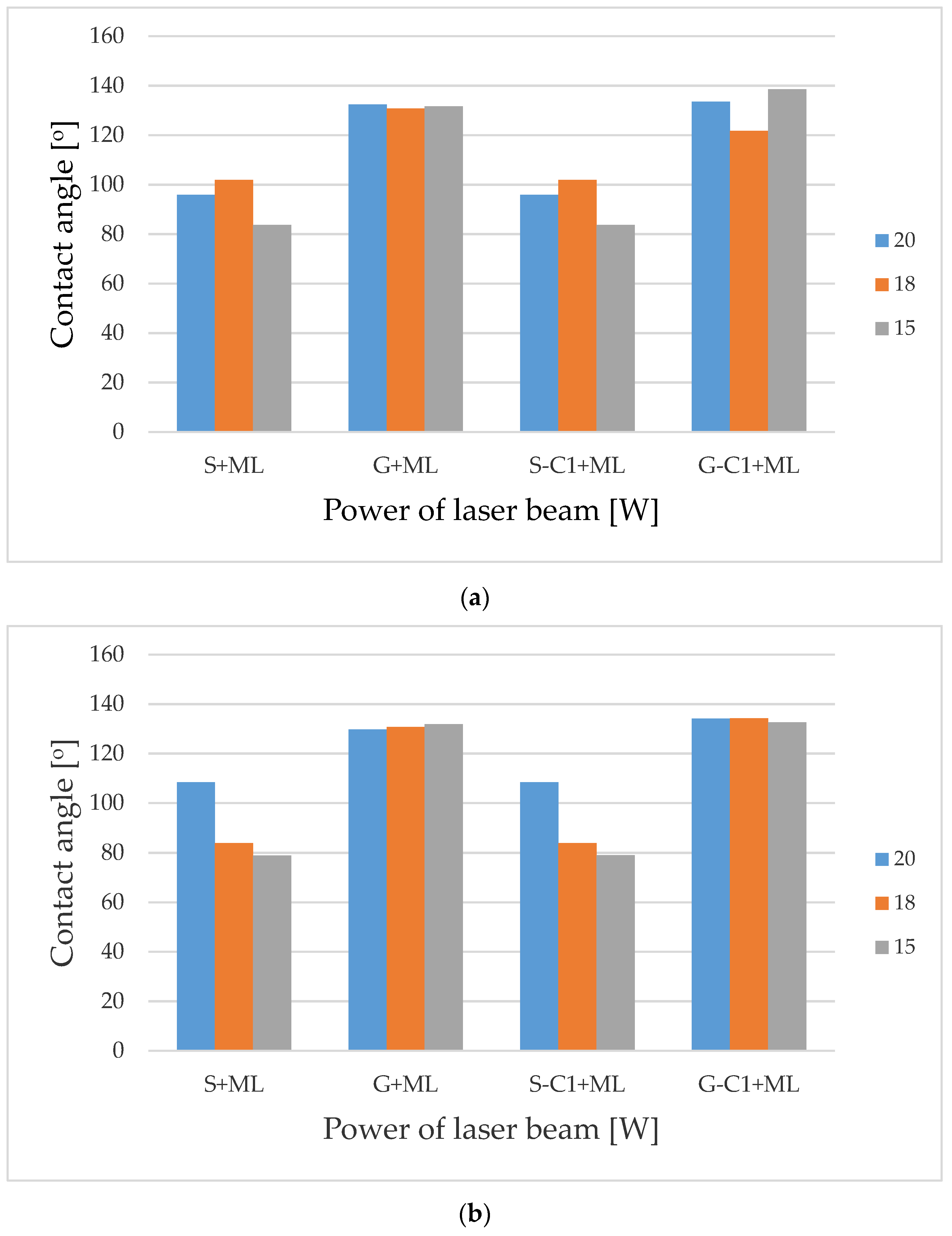
| Factor\Variant | L1 | L2 | L3 | L4 | L5 | L6 | L7 | L8 | L9 | L10 | L11 |
|---|---|---|---|---|---|---|---|---|---|---|---|
| Mean power of the laser beam [W] | 20 | 18 | 15 | 20 | 15 | 20 | 20 | 18 | 15 | 20 | 15 |
| Pulse duration [ns] | 220 | 220 | 220 | 220 | 220 | 220 | 120 | 120 | 120 | 55 | 55 |
| Scanning speed [mm/s] | 300 | 300 | 300 | 300 | 300 | 300 | 470 | 470 | 470 | 770 | 770 |
| Pulse repetition frequency [kHz] | 35 | 35 | 35 | 35 | 35 | 35 | 55 | 55 | 55 | 90 | 90 |
| Hatching [µm] | 100 | 100 | 100 | 100 | 100 | 50 | 50 | 50 | 50 | 50 | 50 |
| Number of repetitions | 10 | 10 | 10 | 4 | 5 | 4 | 5 | 5 | 5 | 5 | 10 |
| Before Modification | After Chemical Modification | After Laser Modification | |
|---|---|---|---|
| C1 | Without Chemical Modification | C1 | |
| S (smooth) | S-C1 | S—from L1 to L11 | S-C1 from L1 to L11 |
| G (geometrised) | G-C1 | G—from L1 to L11 | G-C1 from L1 to L11 |
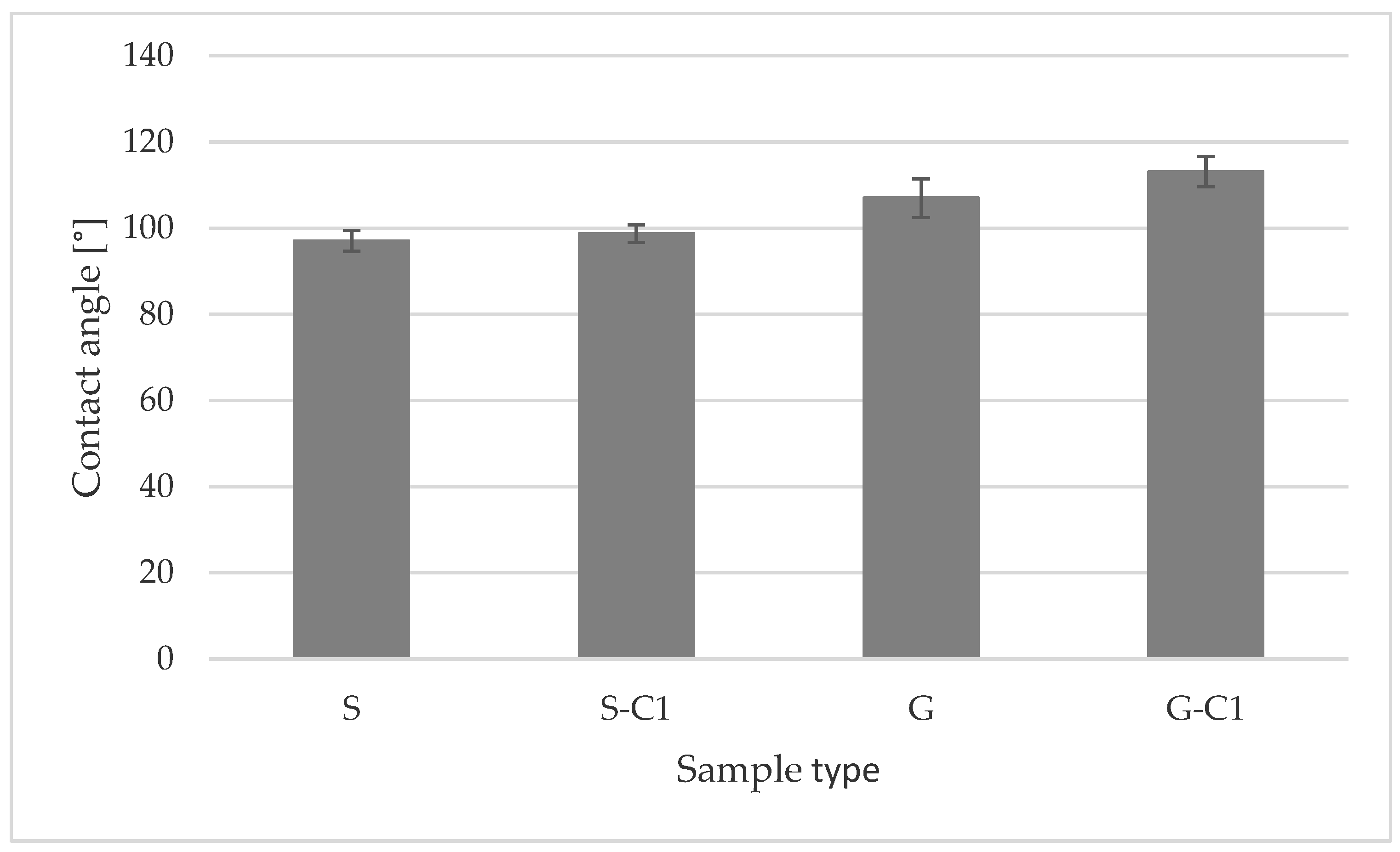
| No. | S | S-C1 | G | G-C1 |
|---|---|---|---|---|
| 1 | 98.8 | 98.4 | 114.7 | 109.5 |
| 2 | 99.5 | 98.9 | 102.2 | 108.8 |
| 3 | 96.2 | 94.8 | 107.6 | 116.2 |
| 4 | 94.2 | 99.9 | 112.0 | 114.5 |
| 5 | 94.1 | 97.1 | 105.9 | 110.3 |
| 6 | 94.6 | 102.4 | 110.7 | 118.2 |
| 7 | 97.3 | 100.3 | 108.6 | 115.8 |
| 8 | 99.1 | 97.7 | 102.1 | 116.4 |
| 9 | 95.9 | 99.9 | 102.0 | 109.3 |
| 10 | 100.8 | 98.0 | 104.0 | 112.4 |
| Mean value | 97.05 | 98.74 | 106.98 | 113.14 |
| SD | 2.41 | 2.07 | 4.51 | 3.5 |
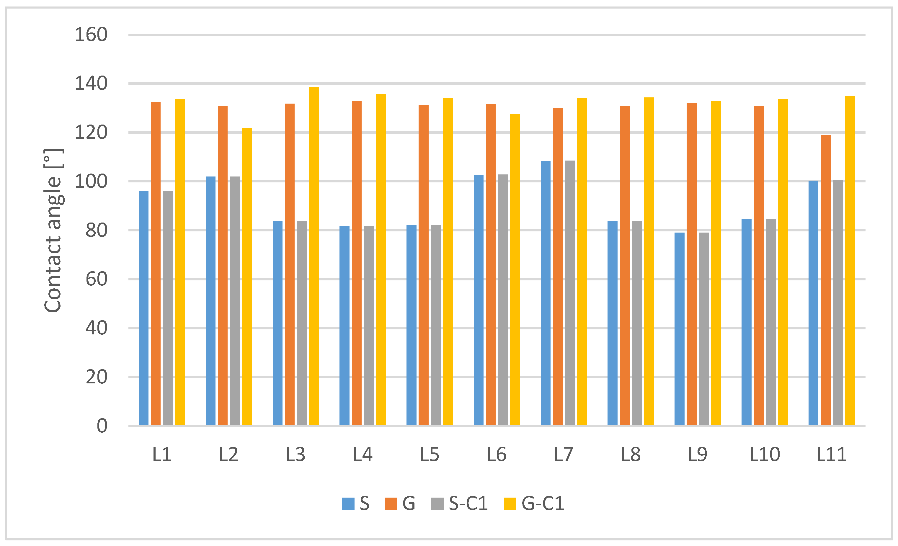
| Non-Modified | After C1 Surface Modification | |||||||
|---|---|---|---|---|---|---|---|---|
| Sample Number | S | Δϕ | G | Δϕ | S-C1 | Δϕ | G-C1 | Δϕ |
| L1 | 95.85 | −1.20 | 132.4 | 33.66 | 95.92 | −11.06 | 133.47 | 20.33 |
| L2 | 101.85 | 4.80 | 130.75 | 32.01 | 101.92 | −5.06 | 121.77 | 8.63 |
| L3 | 83.65 | −13.40 | 131.65 | 32.91 | 83.72 | −23.26 | 138.57 | 25.43 |
| L4 | 81.65 | −15.40 | 132.8 | 34.06 | 81.72 | −25.26 | 135.72 | 22.58 |
| L5 | 81.95 | −15.10 | 131.27 | 32.53 | 82.02 | −24.96 | 134.17 | 21.03 |
| L6 | 102.65 | 5.60 | 131.42 | 32.68 | 102.72 | −4.26 | 127.37 | 14.23 |
| L7 | 108.35 | 11.30 | 129.77 | 31.03 | 108.42 | 1.44 | 134.12 | 20.98 |
| L8 | 83.75 | −13.30 | 130.67 | 31.93 | 83.82 | −23.16 | 134.27 | 21.13 |
| L9 | 78.95 | −18.10 | 131.82 | 33.08 | 79.02 | −27.96 | 132.62 | 19.48 |
| L10 | 84.45 | −12.60 | 130.62 | 31.88 | 84.52 | −22.46 | 133.52 | 20.28 |
| L11 | 100.25 | 3.20 | 118.92 | 20.18 | 100.32 | −6.66 | 134.67 | 21.53 |
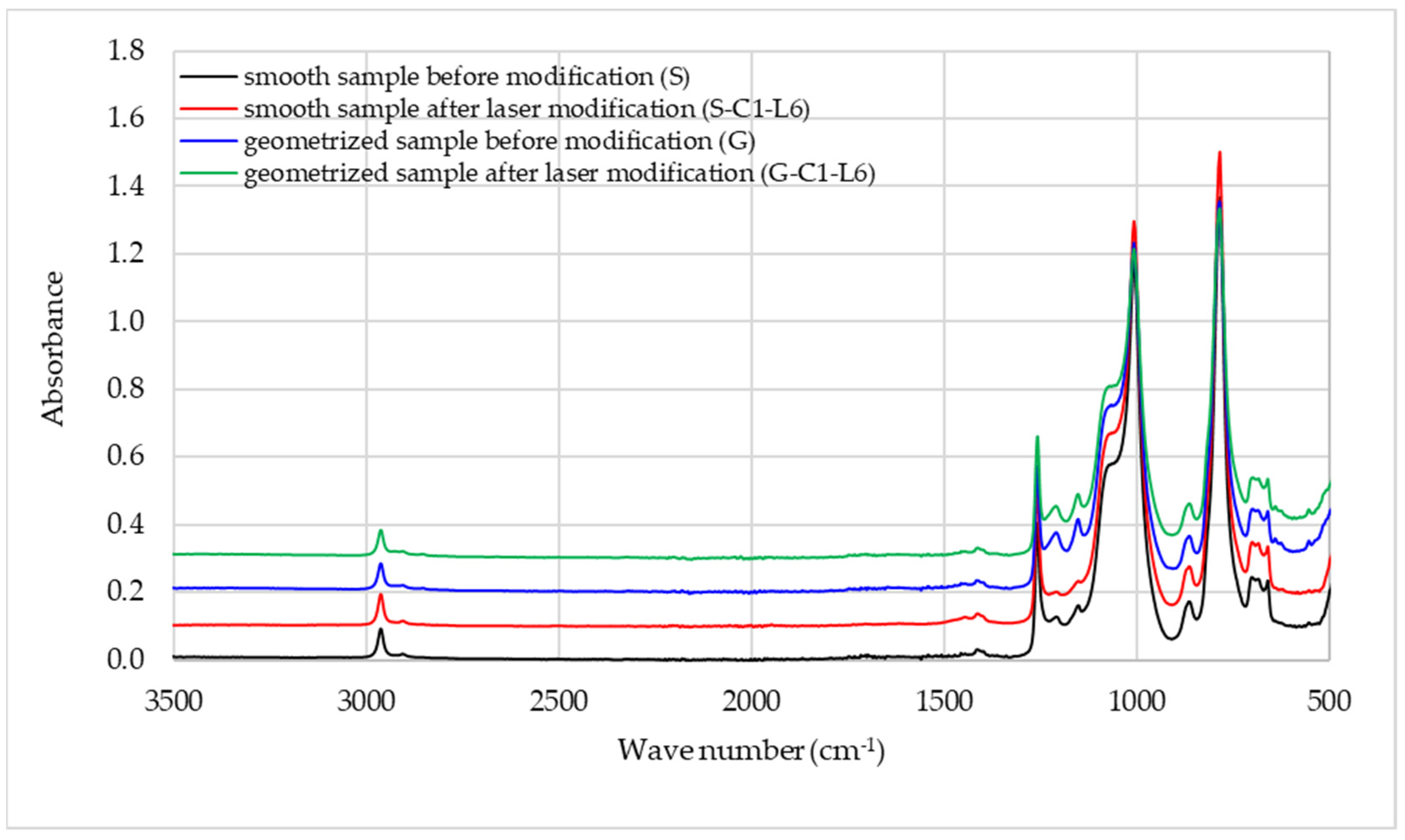
| Wavenumber (cm−1) | Band Intensity | Chemical Group |
|---|---|---|
| 2962 | Medium | C-H in CH3 |
| 2872 | Very weak | C-H in CH3 |
| 1412 | Weak | CH3 in Si-CH3 |
| 1258 | Intensive, sharp | Si-CH3 |
| 1210 | Weak | C-C in CH3 * |
| 1153 | Weak | C-C in CH3 * |
| 1100–1000 | Intensive, broad | Si-O-Si |
| 864 | Medium | Si-O in O-Si-CH3 |
| 785 | Intensive, sharp | C-Si-C |
| 700–660 | Medium doublet | Si in C-Si-C |
Publisher’s Note: MDPI stays neutral with regard to jurisdictional claims in published maps and institutional affiliations. |
© 2021 by the authors. Licensee MDPI, Basel, Switzerland. This article is an open access article distributed under the terms and conditions of the Creative Commons Attribution (CC BY) license (https://creativecommons.org/licenses/by/4.0/).
Share and Cite
Irzmańska, E.; Korzeniewska, E.; Pawlak, R.; Tomczyk, M.; Smejda-Krzewicka, A.; Adamus-Włodarczyk, A. Enhanced Hydrofobicity of Polymers for Personal Protective Equipment Achieved by Chemical and Physical Modification. Materials 2022, 15, 106. https://doi.org/10.3390/ma15010106
Irzmańska E, Korzeniewska E, Pawlak R, Tomczyk M, Smejda-Krzewicka A, Adamus-Włodarczyk A. Enhanced Hydrofobicity of Polymers for Personal Protective Equipment Achieved by Chemical and Physical Modification. Materials. 2022; 15(1):106. https://doi.org/10.3390/ma15010106
Chicago/Turabian StyleIrzmańska, Emilia, Ewa Korzeniewska, Ryszard Pawlak, Mariusz Tomczyk, Aleksandra Smejda-Krzewicka, and Agnieszka Adamus-Włodarczyk. 2022. "Enhanced Hydrofobicity of Polymers for Personal Protective Equipment Achieved by Chemical and Physical Modification" Materials 15, no. 1: 106. https://doi.org/10.3390/ma15010106