1. Introduction
Joining metals by welding is nowadays widely used in the construction of most engineering structures. The requirements for high quality welded joints joining similar or dissimilar metals, taking into account the mechanical properties of the metal, lead to the production of welded joints with significant differences in strength compared to the base metal.
Like all structures, welded structures are susceptible to damage during use, particularly in the weld or heat-affected zone, due to the change in metal properties and the expected significant nonlinear deformations caused by mechanical heterogeneity. Repaired welds are commonly used in steel structures either to correct initial fabrication defects or to repair damage during service to extend the service life of the structure [
1]. When welds are repaired, additional heterogeneity is introduced into the already heterogeneous structure.
In the conventional evaluation of the safe operation of defect-free structures, the applied stresses are compared to a limit stress, such as the yield strength of the material. When damage in the form of a crack is present, the assessment of welded joints is based on the evaluation of the stress intensity factor, the J-integral and the crack tip opening displacement (CTOD) [
2]. On the other hand, the influence of mechanical heterogeneity on the fracture behavior of welds is not explicitly included in the mentioned fracture mechanics parameters. However, methods and procedures for evaluating homogeneous and heterogeneous structures, which have been developed recently, can be used to determine whether or not the structure is safe for further exploitation.
One commonly used procedure for a structural integrity assessment is the SINTAP procedure (
Structural
INTegrity
Assessment
Procedure) [
3]. The application of the SINTAP procedure is based on the implementation of the yield load solution in the failure assessment diagram (FAD) to determine the safe operation of the assessed structure. There are a number of studies dealing with various aspects of the fracture behavior of homogeneous welds with strength mismatch compared to the base metal, including recent ones [
4,
5,
6,
7,
8,
9], as well as a number of studies dealing with heterogeneity in welds with strength mismatch [
10,
11,
12,
13,
14,
15,
16].
A common parameter for describing the level of strength mismatch between individual metals, in the context of this investigation, between base metal and weld metals, i.e., mismatch in yield strength between the weld metal and the base metal, is quantified by the mismatch factor
M:
where
σYW and
σYB represent the yield strength of the weld metal and the yield strength of the base metal (BM), respectively, while
M < 1 refers to under-matching (UM) and
M > 1 to over-matching (OM).
Yield load solutions are available for a limited number of strength mismatch configurations for over-matched and under-matched welds [
17,
18,
19,
20], but only very limited and partial solutions in situations where additional heterogeneity due to repair weld metal is present in another level of the strength mismatch [
21,
22]. Therefore, this research aims to extend the existing yield load solutions to I-shaped heterogeneous weld solutions in order to gain insight into the fracture behavior of the repaired weld and open the possibility of applying structural assessment procedures for repair welds. As a result, a compendium of yield load solutions for a standard fracture mechanics specimen SE(B) with a heterogeneous weld is given, which can be used as the input parameter for an assessment using standard structural integrity assessment procedures.
2. Problem Description and Investigation Plan
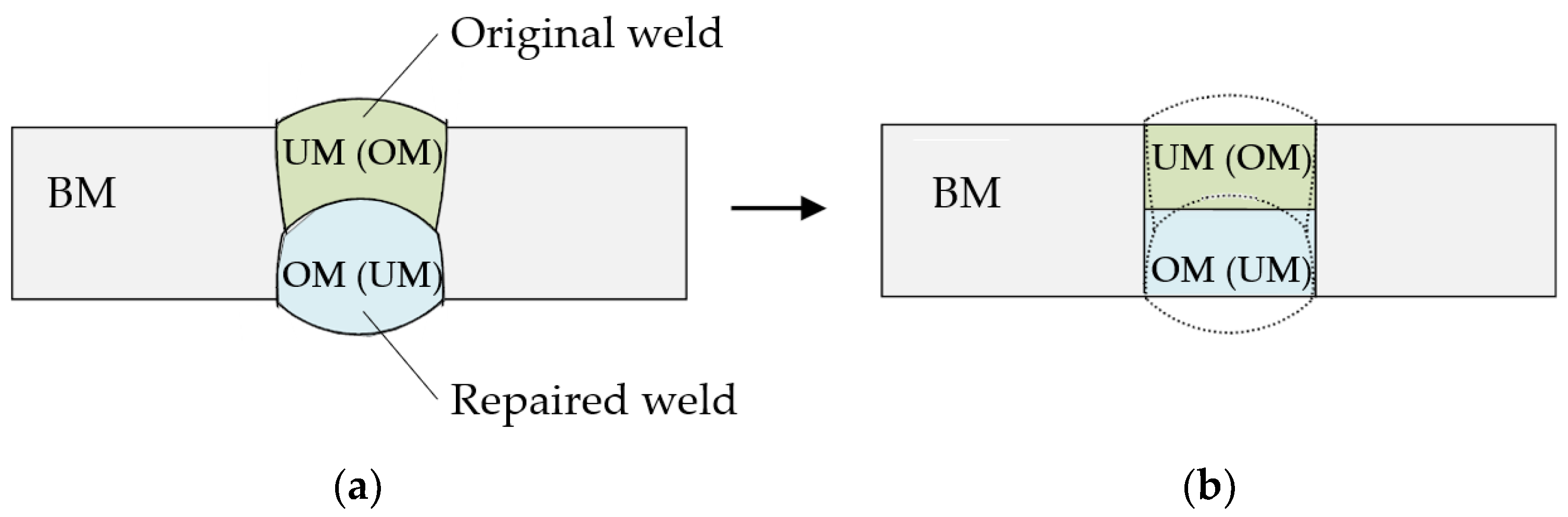
Since butt welds are used extensively in the welding industry, there is often a need to repair such welds when defects occur during welding or during the service life of the welded structure. If the repair involves the use of a filler metal different from the filler metal used to weld the original weld, the result is a heterogeneous welded joint with two different weld metals in addition to the base metal. When structures are put back into service after repair, the occurrence of cracks in the original part or in the repaired part of the weld is possible again.
For this reason, and for the reasons given in the introduction, a study of the fracture behavior of an I-shaped butt weld was carried out. The effects of weld damage in the form of a crack were analyzed.
Due to the complexity of the problem to be analyzed, it was necessary to introduce certain idealizations and simplifications. In all previous studies on a similar topic, several such idealizations were introduced, starting from the weld geometry idealized by a rectangle, and the observed cracks were located at the interface of dissimilar materials or in the middle of the weld due to the nature of crack formation described in [
18,
23,
24]. In this study, the I-shaped weld was also idealized as a rectangular shape, as well as the original and repaired part of the weld (
Figure 1), and the crack was located in the center of the weld. In [
25], researchers have demonstrated that the mechanical properties of the heat-affected zone have a negligible effect on the stress concentration at the crack tip when the crack tip is located in the center of the weld. However, if the crack tip is located in or near the heat-affected zone, the properties of the heat-affected zone have to be taken necessarily into account [
26]. Since the crack in the middle of the weld was analyzed here, the heat-affected zone was omitted.
The difference in elastic properties of the material as well as the strain hardening of the material affect the fracture behavior of the weld, but here, only the influence of the degree of strength mismatch between the single welded metal and the base metal is studied. In addition to the strength mismatch, the change in weld width and the crack size were also analyzed. The influence of mentioned geometrical and mechanical parameters on the yield load was observed, i.e., the load at which the metal flows through the entire cross-section of the weld, since at that moment a plastic hinge is formed.
3. Finite Element Analysis
In order to investigate the influence of weld material heterogeneity on weld fracture behavior, the weld area was divided into two zones of equal size but consisted of different metals. The first zone represented the original weld before repair, while the second zone represented the repaired portion of the weld. In the first variant, the zone of the original weld was made of a metal whose yield strength was lower than the yield strength of the base metal (UM), while the second half of the weld was made of a metal whose yield strength was higher than the yield strength of the base metal (OM). In the second variant, positions of the UM and OM part of the weld were reversed. Combinations where both weld metals have over-match or under-match character were not covered by this investigation.
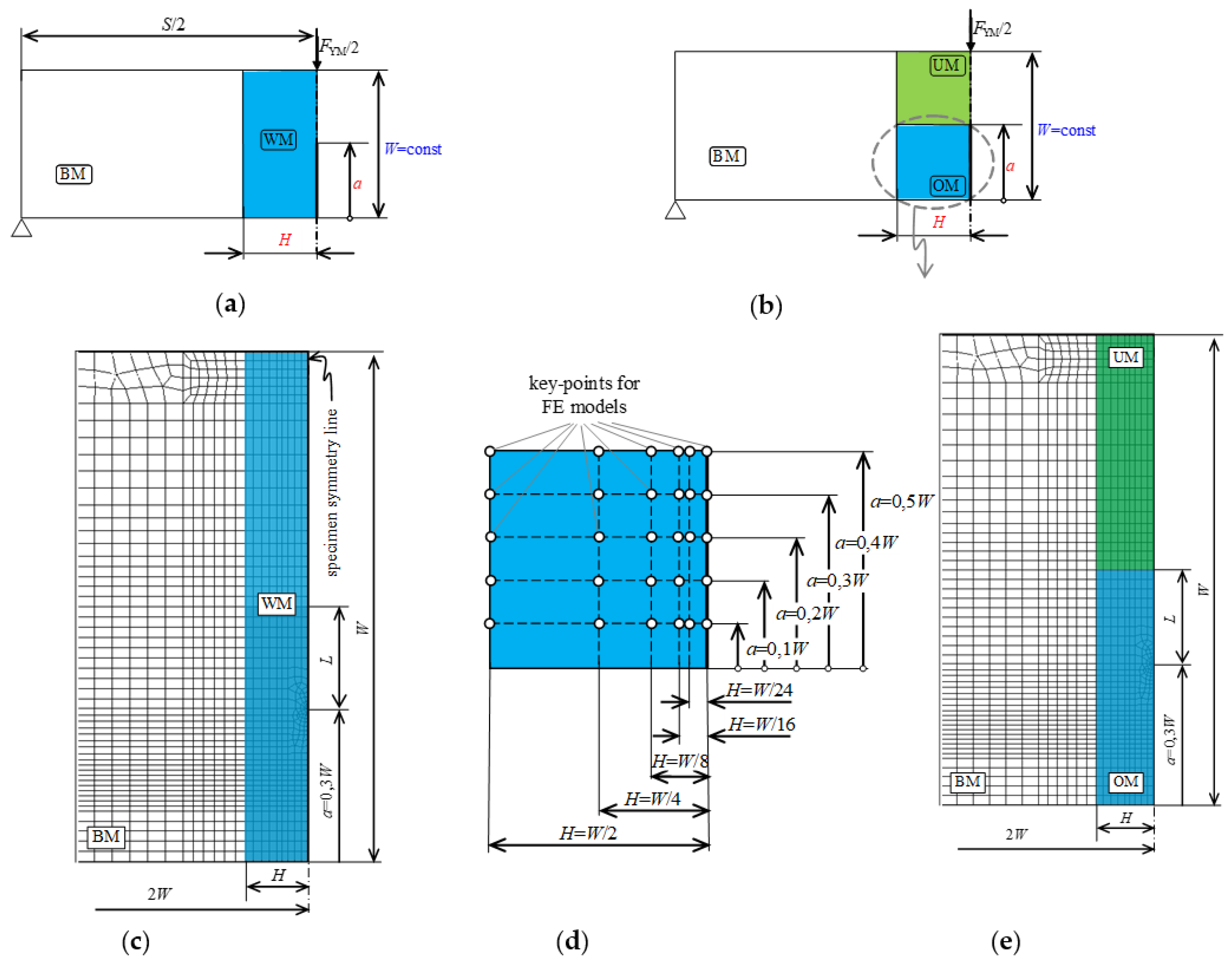
Due to the possibility of crack formation in the original and the repaired part of the weld, both variants were analyzed. Due to geometry and load symmetry, a plane strain two-dimensional numerical model of one half of an SE(B) specimen with homogeneous weld metal (WM) was created in ANSYS [
27] (
Figure 2a,c). The model was verified comparing finite element results with the analytical method of slip line field analysis [
17] that is used in the analytical analysis of strength mismatch welds. Results of verification showed very good agreement between the results of numerical and slip line field analyses, and this verification is already published in [
21]. A single change was made to the verified numerical model, in the form of splitting the homogeneous weld into two equal portions of over-matched and under-matched weld metal to form a heterogeneous weld (
Figure 2b,e).
To determine the influence of weld width
H and crack length
a on the yield load, the width of the weld
H was varied as
H =
W/2,
H =
W/4,
H =
W/8,
H =
W/16 and
H =
W/24, while the crack length in relation to the height of the specimen
W was varied as
a/
W = 0.1,
a/
W = 0.2,
a/
W = 0.3,
a/
W = 0.4 and
a/
W = 0.5 (
Figure 2d). The length of the specimen
S was kept constant.
The base metal (BM) and the weld metals (OM and UM) were modeled as isotropic linearly elastic and nearly ideally plastic materials with Poisson’s ratio of 0.3 and with a Young’s modulus of 202 GPa for base metal, 200 GPa for over-matched and 206 GPa for under-matched metal. Elasticity mismatch also have an influence on the fracture behavior of a welded joint [
28,
29], but this slight degree of elasticity mismatch did not show an influence on the values of the obtained yield loads compared to ones obtained without elasticity mismatch. The yield strength of the base metal was 545 MPa. The strength mismatch of base and weld metals are varied on three levels: over-match metal with mismatch factor
MOM = 2, 1.5 and 1.19 and under-match metal with mismatch factor
MUM = 0.86, 0.75 and 0.5. Yield strength and mismatch factors
MUM = 0.86 and
MOM = 1.19 were chosen due to later comparison to experimental results.
Due to the faster convergence of the results, a practically negligible strain hardening exponent was used, which did not affect the results but significantly reduced the computation time. To avoid the incompressibility problem, an isoparametric planar element with eight nodes, plane strain and reduced integration was used. Singular elements with a size of 100 µm were used in the first ring of elements around the crack tip to produce the square root singularity of the stress–strain field. Models were meshed with 1847 finite elements and with 5690 nodes. Prepared models were loaded with a load large enough to cause the material to yield through the entire cross-section of the model.
The load was increased gradually in small increments to accurately determine the load of plasticization of the entire net section of the specimen, indicating the formation of a plastic hinge and plastic collapse. As a criterion for material flow, the von Mises criterion was used. A total of 450 simulations were performed for a crack located in an over-matched and under-matched part of the weld.
4. Results of Finite Element Analysis
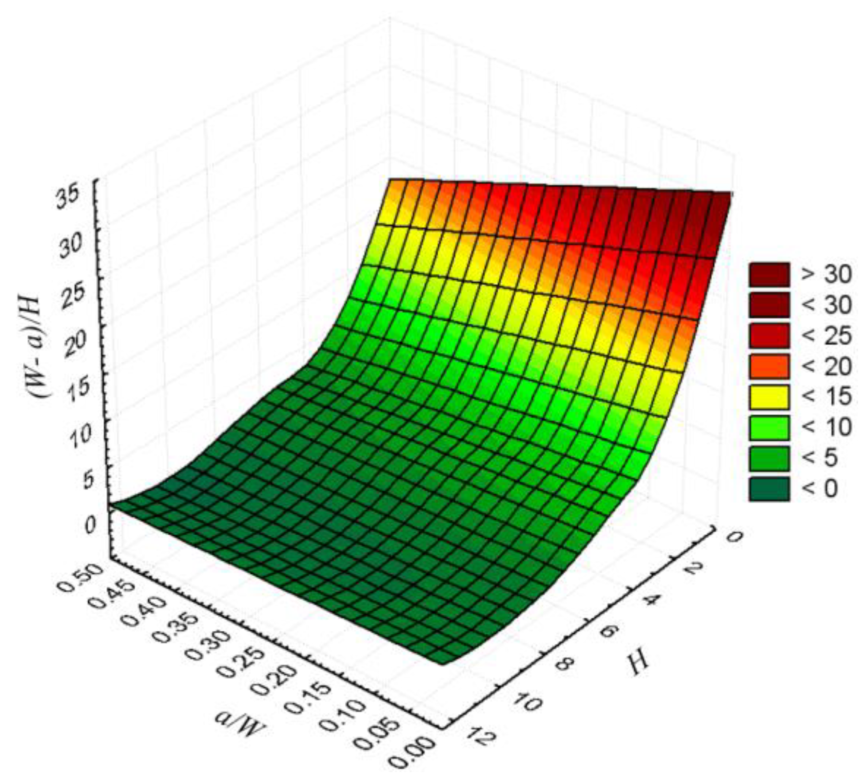
Obtained yield loads for heterogeneous weld were normalized with yield loads of all base specimen according to [
17] and presented in diagrams depending on the weld slenderness (
W −
a)/
H. To facilitate the interpretation of the results, the dependence of weld slenderness on crack length and weld width is shown in
Figure 3. It can be seen that the slenderness of the weld increases significantly with decreasing weld width and becomes less pronounced with decreasing crack length.
4.1. Yield Load Solutions for a Crack in the Over-Matched Part of the Weld
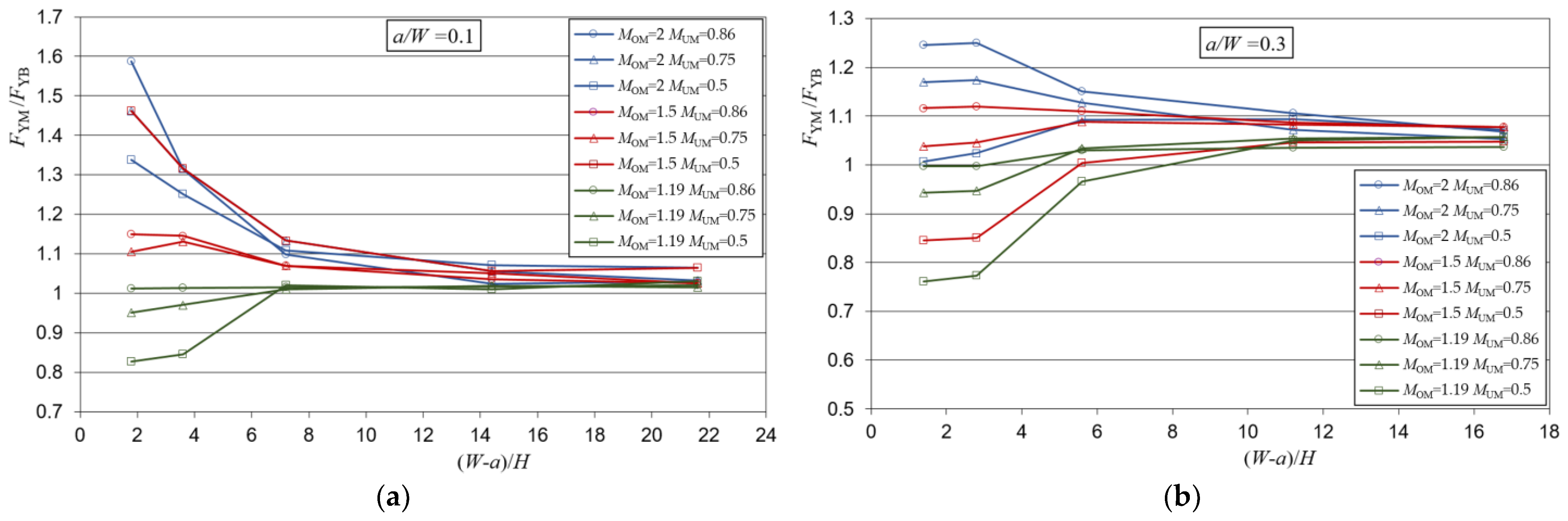
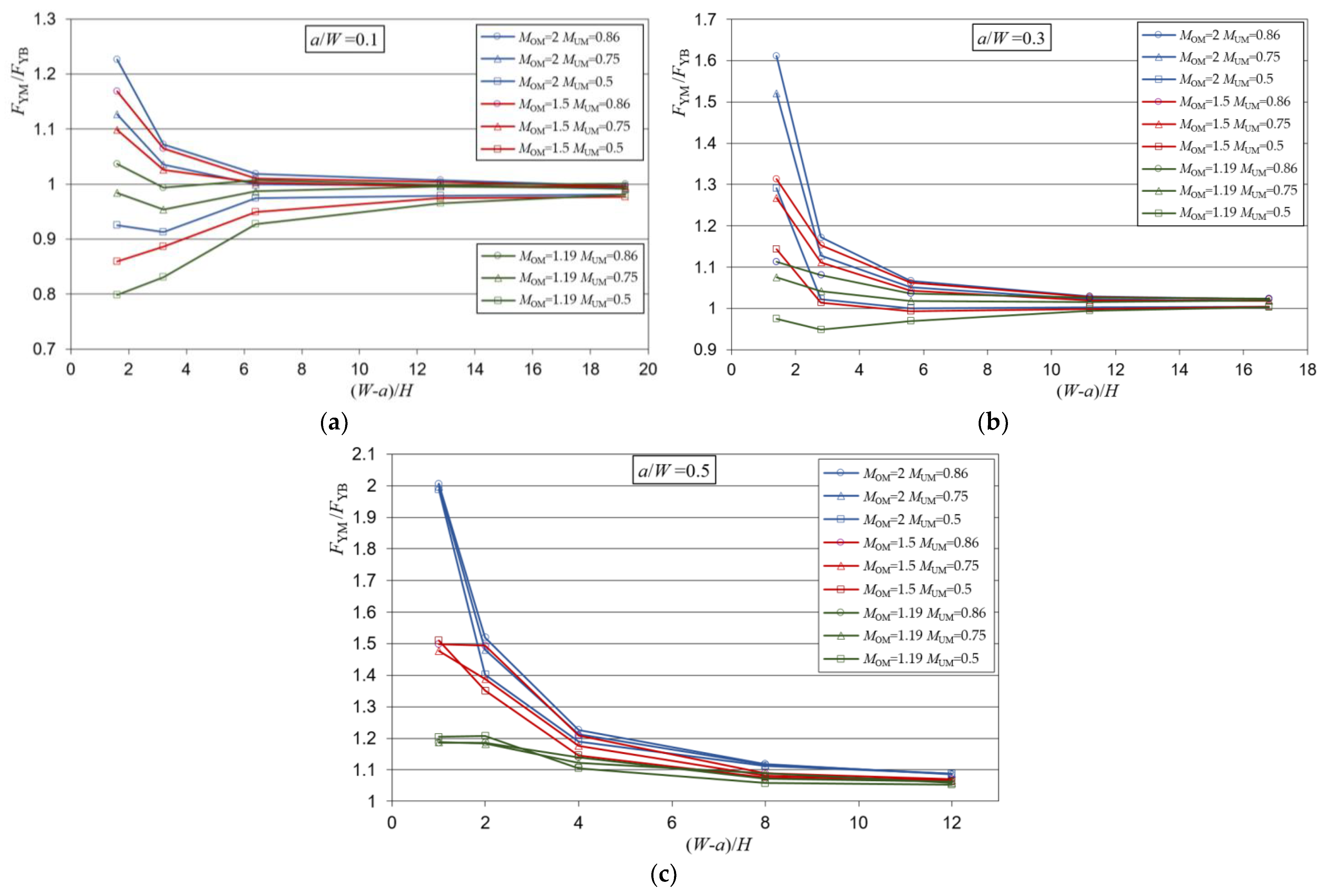
Yield load solutions as a result of the analysis of a heterogeneous weld with a crack in the over-matched part of the weld in the function of weld slenderness (
W −
a)/
H are presented in
Figure 4.
From
Figure 4, it can be seen that the dispersion of the yield load solutions at lower weld slenderness depends on the present weld metals, while at higher weld slenderness, the solutions of all metal combinations and all crack lengths approach an asymptotic value. This value is slightly higher than the value 1, indicating a slight increase in the strength of the weld compared to the component of the homogeneous base metal.
When the slenderness of the weld is lower, different effects occur depending on the length of the crack in the weld. For the crack a/W = 0.5, there is only under-matched metal in front of the crack, which is represented by the mismatch factor MUM. Therefore, the solutions were the values 0.5, 0.75 and 0.86 because the dominant metal is in front of the crack. Although the solutions were these values, it is noticeable that they are actually slightly larger, which is a consequence of the formation of the yield zone partially through the over-matched metal too, which has a higher value of the mismatch factor MOM.
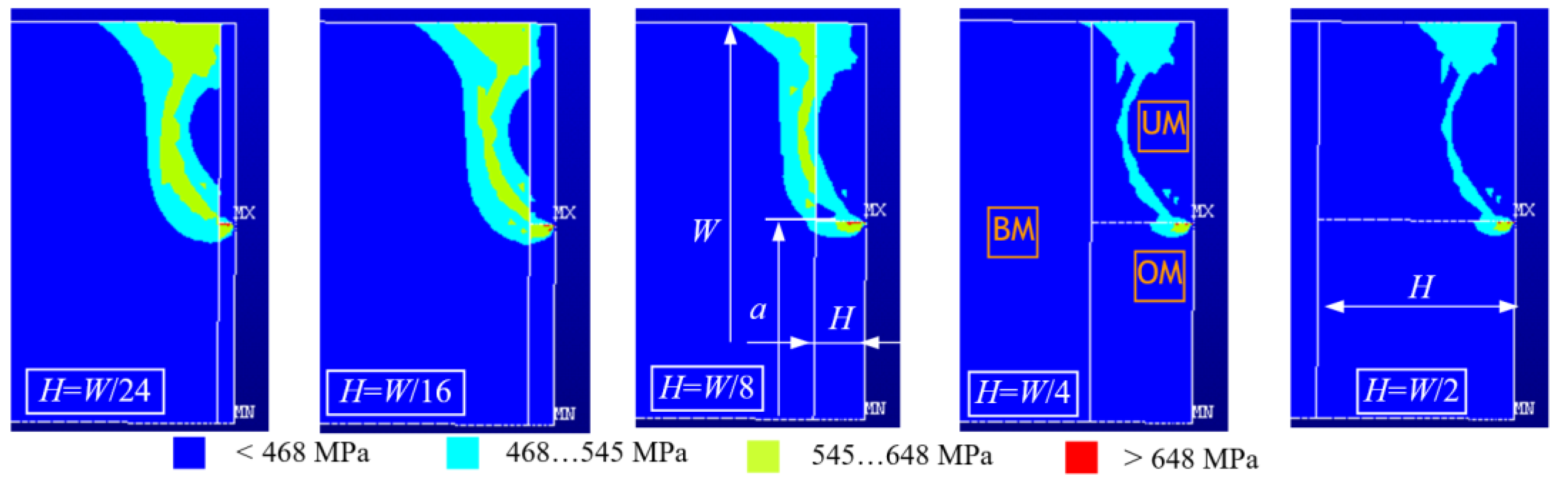
Figure 5 shows formation of the yield zone in a heterogeneous weld with a crack in the over-matched part of the weld for varying weld width
H and constant crack length
a/
W = 0.5 for mismatch factors
MOM = 1.19 and
MUM = 0.86.
The appearance of the yield zones is similar for all geometries, and depending on the width of the weld, the yield zone extends through two or all three materials. For narrow weld widths H = W/24, H = W/16 and H = W/8, the material yield zone spreads through the base metal and both weld metals, while for wider welds H = W/4 and H = W/2, the yield zone stays within the weld metal.
As the size of the crack decreases, the metal in which the crack is located becomes more influential. This is particularly pronounced for combinations of metals whose mismatch factors MOM and MUM differ significantly, while the solutions for combinations of metals with closer values of MOM and MUM approach the values of 1 of the base metal. For example, for the combination of metals MOM = 2 and MUM = 0.5, the solutions range from 0.5 to 1.6, and for the combination of MOM = 1.19 and MUM = 0.86, the solutions are almost everywhere uniform and closer to the value 1.
The results of the numerical analyses for a crack in the over-matched part of the weld were processed in the software package TuringBot [
30] using a symbolic regression algorithm to derive mathematical formulas from numerically obtained values with high efficiency. An equation that estimates the values of the ratio of the yield loads for the heterogeneous weld and the whole base metal was obtained. A high goodness-of-fit of the selected model was confirmed with the R-squared value 0.938 and RMS error 0.03748. The equation considers values of the over-match strength mismatch
MOM, under-match strength mismatch
MUM, the weld width
H and the crack length
a/
W:
4.2. Yield Load Solutions for a Crack in the Under-Matched Part of the Weld
Yield load solutions as a result of the analysis of a heterogeneous weld with a crack in the under-matched part of the weld in the function of weld slenderness (
W −
a)/
H are presented in
Figure 6.
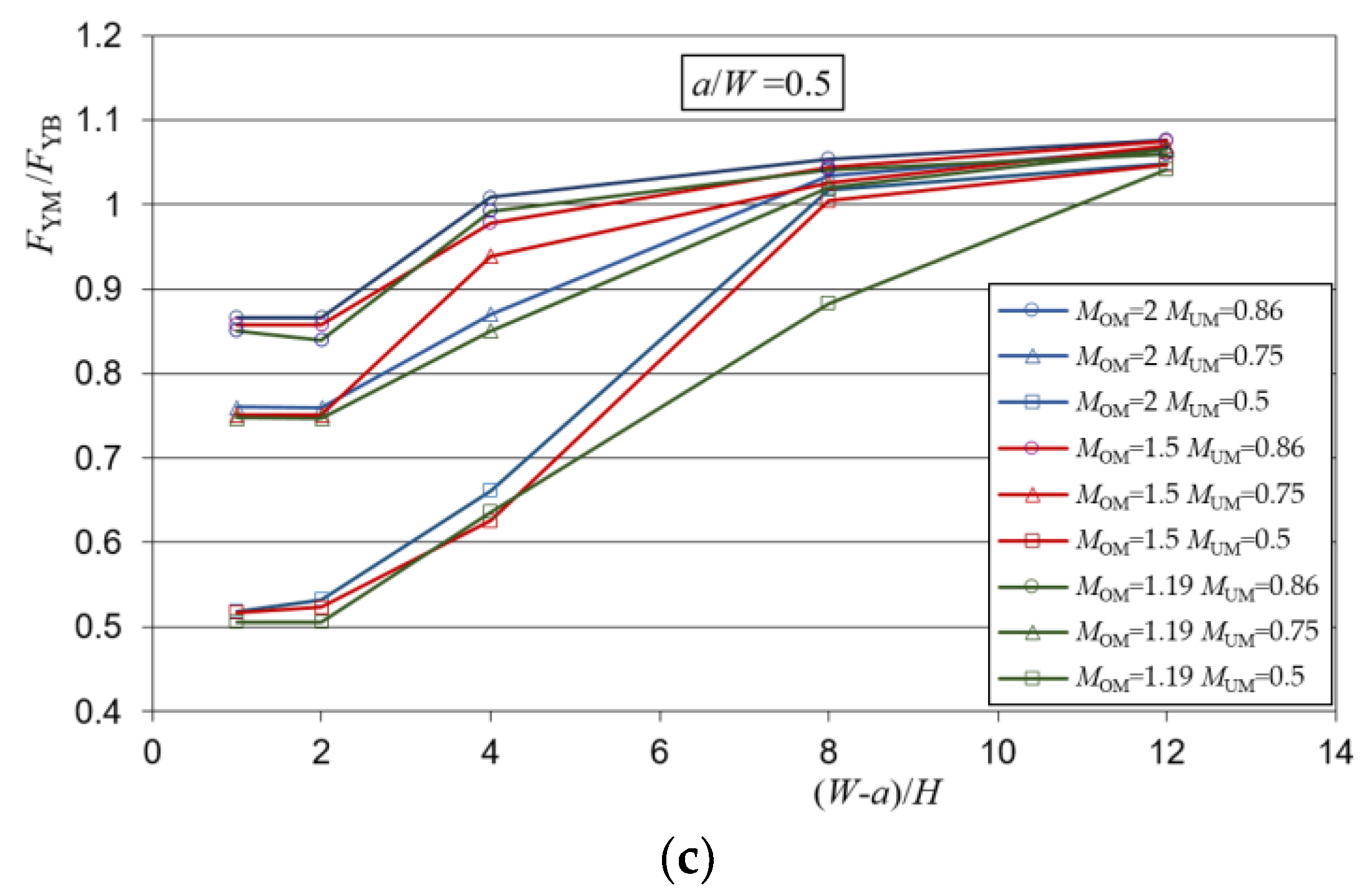
Results of the analysis, shown in
Figure 6, indicated that for lower weld slenderness, the yield load solutions differ depending on the weld metals present in the weld, while for higher weld slenderness, the yield solutions of all metal combinations, as well as for all crack lengths, approached the value 1.
When the weld was less slender, the weld showed different behavior depending on the length of the crack in the weld. For the crack a/W = 0.5, only the OM was in front of the crack, therefore the yield loads were the values 1.19, 1.5 and 2. This happens because the metal in front of the crack, which has the over-match characteristic, takes the dominant role. Although the solutions were these values, it can be noted that they were somewhat lower, which was a consequence of the partial propagation of the yield zone also through the under-matched metal.
As the length of the crack decreases, the metal in which the crack is located also becomes more influential. Similar to the case where the crack was in an over-matched metal, it can be observed that the solutions with closer values of MOM and MUM approached the values of 1 of the base metal. For example, for the combination of MOM = 2 and MUM = 0.5, the solutions ranged from 0.9 to 2, and for the combination of MOM = 1.19 and MUM = 0.86, the solutions were almost uniform and were everywhere closer to the value of 1.
The results of the analysis for a crack in the under-matched part of the weld were also processed in the software package TuringBot using a symbolic regression algorithm and an equation for the estimation of the values of the ratio of yield loads for the heterogeneous weld and the whole base metal was obtained:
A high goodness-of-fit for model with a crack in the under-matched part of the weld was confirmed with the R-squared value 0.953 and RMS error 0.04095.
5. Experimental Investigation
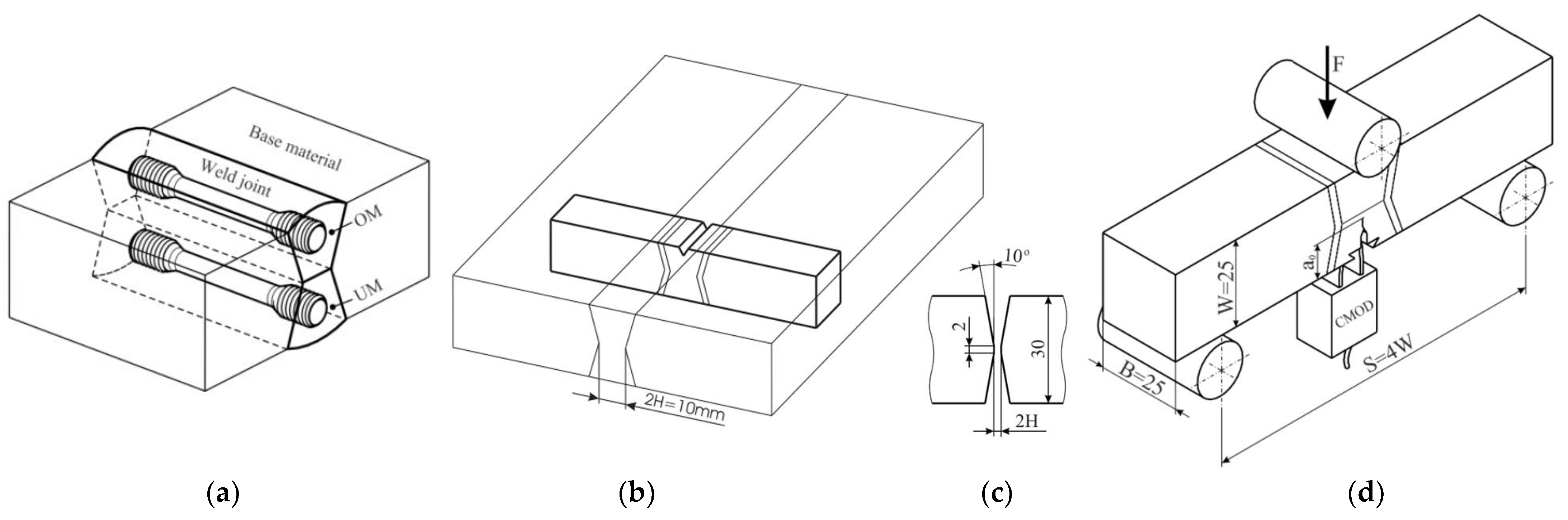
For this investigation, standard SE(B) test specimens were prepared from the welded plate. For the base metal (BM), NIOMOL 490 was used as a high-strength, low-alloy, fine-grain steel in the hardened and tempered condition according to the HT 50 grade. Using the flux cord arc welding procedure and two tubular wires as filler material FILTUB 75 and VAC 60 as an over-match and under-match material, a heterogeneous weld was produced with the strength mismatch factor 1.19 and 0.86. Mechanical properties of the base metal and OM and UM part of the weld, shown in
Table 1, were obtained by a tensile test. Five round specimens with a 5 mm diameter were used for each metal. The position and orientation of round specimens in the weld joint are shown in
Figure 7a. The chemical composition of BM, UM and OM metal, shown in
Table 2, is provided by the manufacturer, where OM and UM chemical composition is provided for pure weld metal.
For fracture toughness testing, specimens were prepared, and a single-sample method was used according to the standard BS 7448 [
31]. CTOD fracture toughness specimens with dimensions and notch orientation are shown on
Figure 7. The CTOD tests were carried out at room temperature (+24 °C) under displacement control (1 mm/min). Load
F, total displacement, crack tip (CTOD) and crack mouth opening displacement (CMOD) were recorded during the tests. Tests were performed for two configurations: with a crack in the over-matched part of the weld and with a crack in the under-matched part of the weld. A total of 14 specimens were tested: 7 specimens with a crack initiated in the OM part of the weld and 7 with a crack initiated in the UM part of the weld.
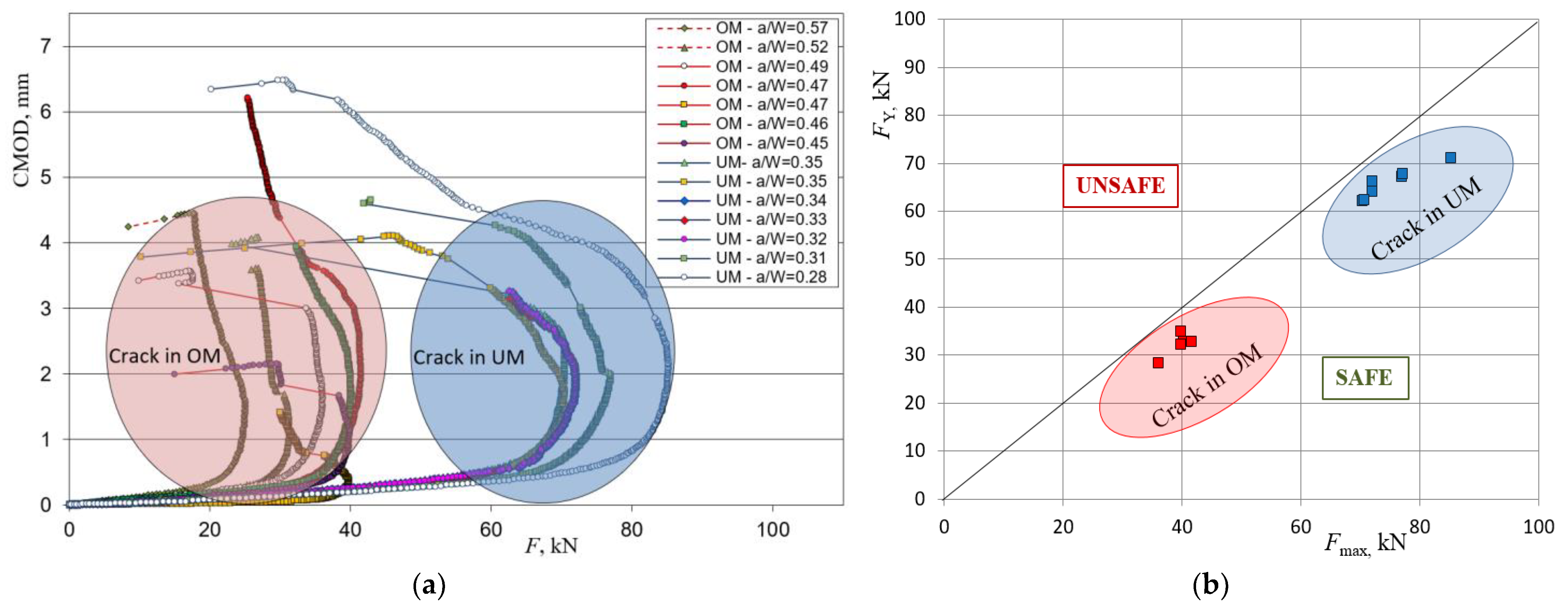
The plots of load versus CMOD were obtained and shown in
Figure 8a. During fatigue pre-cracking in two specimens, with a notch in the OM part of the weld, a crack reached the fusion line between the OM and UM and advanced to the UM part of the weld (
Figure 8a shown with dotted lines); therefore, they are omitted in later comparison with the yield load solutions for a heterogeneous weld. For every sample, a crack location (OM or UM) and initial crack length compared to the height of the specimen (
a/
W) is shown in the legend.
From the loading curve plots, it can be seen that every specimen for each configuration shows a certain period of stable crack propagation and reaches a maximum load, followed by a load decrease and unstable crack propagation. The difference in slopes in the diagrams and values of maximum load were due to different initial crack lengths and position of the crack (OM or UM part of the weld), and a separation of curves for the crack located in the OM part of the weld and advancing to the UM and vice versa can be noted.
The maximum load was determined for each specimen and compared with the yield load solutions obtained by expressions (2) and (3). This comparison is presented in
Figure 8b with a yield load versus maximum load plot. Grouping of results is noted for all specimens with a crack in the OM part of the weld as well as with a crack in the UM part of the weld. This was due to relatively similar crack lengths and location of the crack either in the OM or in the UM part of the weld. Yield loads generated from numerically obtained mathematical models for the crack located in the OM and UM part of the weld were lower and conservative enough compared to experimental results. However, it is likely that even less conservative results could be obtained if yield load solutions were implemented as input parameters for evaluating the welded component using structural integrity assessment procedures.
6. Conclusions
As a result of a systematic numerical study, the yield load solutions for SE(B) specimens with a heterogeneous I-shaped weld with an equal share of over-matched and under-matched metal in a welded joint were obtained. Comparing the numerically obtained results in terms of crack position, it can be concluded that a heterogeneous welded joint with a crack in the under-matched metal shows a higher loading capacity than a welded joint with a crack in the over-matched part of a weld. This indicates that in the context of yield load, the metal in front of the crack has a greater effect on the fracture resistance than the metal in which the crack is located. This effect is more pronounced for welds with lower values of weld slenderness (W − a)/H. After processing of the numerically obtained results using a symbolic regression algorithm, solutions for the yield loads were proposed with two models: for the crack in the under-matched and for the crack in the over-matched part of the weld. The models were validated with experimental results and they provided sufficiently conservative results compared to the experiment.
Author Contributions
Conceptualization, P.K. and M.K.; methodology, P.K. and N.G.; validation, P.K., D.K. and N.G.; formal analysis, P.K. and M.K.; investigation, P.K. and M.K.; data curation, P.K.; writing—original draft preparation, P.K.; writing—review and editing, P.K., M.K., D.K. and N.G.; visualization, P.K. All authors have read and agreed to the published version of the manuscript.
Funding
Research is funded by EU project Center of Competences for Advanced Engineering Nova Gradiška (CEKOM NI NG) KK.01.2.203.0011 financed by European Regional Development Fund with support of Ministry of the Economy, Entrepreneurship and Crafts of the Republic of Croatia. Experiments were funded by the Marie Curie Fellow Programme No. MCFI-1999-00314.
Institutional Review Board Statement
Not applicable.
Informed Consent Statement
Not applicable.
Data Availability Statement
Not applicable.
Acknowledgments
Nenad Gubeljak acknowledges the European Commission in the frame of the Marie Curie Fellow Programme with the project titled “An estimation of the integrity of a welded structure regarding Constraint” No. MCFI-1999-00314 for funding at the GKSS Research Centre Geesthacht (today named Helmholtz Zentrum Hereon), Institute of Material and Process Design Germany.
Conflicts of Interest
The authors declare no conflict of interest.
References
- Chen, Z.; Wang, P.; Wang, H.; Xiong, Z. Thermo-Mechanical Analysis of the Repair Welding Residual Stress of AISI 316L Pipeline for ECA. Int. J. Press. Vessels Pip. 2021. in press. [Google Scholar] [CrossRef]
- Moskvichev, E. Fracture Assessment of Cracked Welded Structures Considering the Heterogeneity of Welded Joints. Procedia Mater. Sci. 2014, 3, 556–561. [Google Scholar] [CrossRef]
- Structural Integrity Assessment Procedures for European Industry (SINTAP); Project BE95–1426, Final Procedure; British Steel Report; British Steel Ltd.: Rotherham, UK, 1999.
- Su, L.; Xu, J.; Song, W.; Chu, L.; Gao, H.; Li, P.; Berto, F. Numerical Investigation of Strength Mismatch Effect on Ductile Crack Growth Resistance in Welding Pipe. Appl. Sci. 2020, 10, 1374. [Google Scholar] [CrossRef]
- Milosevic, N.; Sedmak, A.; Jovicic, R. Analysis of Strain Distribution in Overmatching V Groove Weld Using Digital Image Correlation. Procedia Struct. Integr. 2018, 13, 1600–1604. [Google Scholar] [CrossRef]
- Zhu, L.; Tao, X.Y. The Study of Weld Strength Mismatch Effect on Limit Loads of Part Surface and Embedded Flaws in Plate. Int. J. Press. Vessels Pip. 2016, 139–140, 61–68. [Google Scholar] [CrossRef]
- Jeremić, L.; Sedmak, A.; Petrovski, B.; Ðordević, B.; Sedmak, S. Structural Integrity Assessment of Welded Pipeline Designed with Reduced Safety. Teh. Vjesn. Tech. Gaz. 2020, 27, 1461–1466. [Google Scholar]
- Zhao, H.-S.; Lie, S.-T.; Zhang, Y. Fracture Assessment of Mismatched Girth Welds in Oval-Shaped Clad Pipes Subjected to Bending Moment. Int. J. Press. Vessels Pip. 2018, 160, 1–13. [Google Scholar] [CrossRef]
- Fan, K.; Wang, G.Z.; Tu, S.T.; Xuan, F.Z. Geometry and Material Constraint Effects on Fracture Resistance Behavior of Bi-Material Interfaces. Int. J. Fract. 2016, 201, 143–155. [Google Scholar] [CrossRef]
- Hertelé, S.; O’Dowd, N.; Minnebruggen, K.V.; Verstraete, M.; De Waele, W. Fracture Mechanics Analysis of Heterogeneous Welds: Validation of a Weld Homogenisation Approach. Procedia Mater. Sci. 2014, 3, 1322–1329. [Google Scholar] [CrossRef]
- Zhao, K.; Wang, S.; Xue, H.; Wang, Z. Effect of Material Heterogeneity on Environmentally Assisted Cracking Growth Rate of Alloy 600 for Safe-End Welded Joints. Materials 2021, 14, 6186. [Google Scholar] [CrossRef] [PubMed]
- Starčevič, L.; Gubeljak, N.; Predan, J. The Numerical Modelling Approach with a Random Distribution of Mechanical Properties for a Mismatched Weld. Materials 2021, 14, 5896. [Google Scholar] [CrossRef]
- Naib, S.; Waele, W.D.; Štefane, P.; Gubeljak, N.; Hertelé, S. Analytical Limit Load Predictions in Heterogeneous Welded Single Edge Notched Tension Specimens. Procedia Struct. Integr. 2018, 13, 1725–1730. [Google Scholar] [CrossRef]
- Yu, Y.; Hu, B.; Gao, M.; Xie, Z.; Rong, X.; Han, G.; Guo, H.; Shang, C. Determining Role of Heterogeneous Microstructure in Lowering Yield Ratio and Enhancing Impact Toughness in High-Strength Low-Alloy Steel. Int. J. Miner. Metall. Mater. 2021, 28, 816–825. [Google Scholar] [CrossRef]
- Xue, H.; Wang, Z.; Wang, S.; He, J.; Yang, H. Characterization of Mechanical Heterogeneity in Dissimilar Metal Welded Joints. Materials 2021, 14, 4145. [Google Scholar] [CrossRef] [PubMed]
- Predan, J.; Gubeljak, N.; Kolednik, O. On the Local Variation of the Crack Driving Force in a Double Mismatched Weld. Eng. Fract. Mech. 2007, 74, 1739–1757. [Google Scholar] [CrossRef]
- Kim, Y.-J.; Schwalbe, K.-H. Compendium of Yield Load Solutions for Strength Mis-Matched DE(T), SE(B) and C(T) Specimens. Eng. Fract. Mech. 2001, 68, 1137–1151. [Google Scholar] [CrossRef]
- Kim, Y.-J.; Schwalbe, K.-H. Mismatch Effect on Plastic Yield Loads in Idealised Weldments I. Weld Centre Cracks. Eng. Fract. Mech. 2001, 68, 163–182. [Google Scholar] [CrossRef]
- Kim, Y.-J.; Schwalbe, K.-H. Mismatch Effect on Plastic Yield Loads in Idealised Weldments II. Heat Affected Zone Cracks. Eng. Fract. Mech. 2001, 68, 183–199. [Google Scholar] [CrossRef]
- Kim, S.-H.; Han, J.-J.; Kim, Y.-J. Limit Load Solutions of V-Groove Welded Pipes with a Circumferential Crack at the Centre of Weld. Procedia Mater. Sci. 2014, 3, 706–713. [Google Scholar] [CrossRef][Green Version]
- Kozak, D.; Gubeljak, N.; Konjatić, P.; Sertić, J. Yield Load Solutions of Heterogeneous Welded Joints. Int. J. Press. Vessels Pip. 2009, 86, 807–812. [Google Scholar] [CrossRef][Green Version]
- Konjatić, P.; Kozak, D.; Gubeljak, N. The Influence of the Weld Width on Fracture Behaviour of the Heterogeneous Welded Joint. Key Eng. Mater. 2011, 488, 367–370. [Google Scholar] [CrossRef]
- Hao, S.; Schwalbe, K.-H.; Cornec, A. The Effect of Yield Strength Mis-Match on the Fracture Analysis of Welded Joints: Slip-Line Field Solutions for Pure Bending. Int. J. Solids Struct. 2000, 37, 5385–5411. [Google Scholar] [CrossRef]
- Ford, H.; Alexander, J.M. Advanced Mechanics of Materials; Longman: London, UK, 1963. [Google Scholar]
- Manjgo, M.; Medjo, B.; Milović, L.; Rakin, M.; Burzić, Z.; Sedmak, A. Analysis of Welded Tensile Plates with a Surface Notch in the Weld Metal and Heat Affected Zone. Eng. Fract. Mech. 2010, 77, 2958–2970. [Google Scholar] [CrossRef]
- Zhang, Z.L.; Thaulow, C.; Hauge, M. Effects of Crack Size and Weld Metal Mismatch on the HAZ Cleavage Toughness of Wide Plates. Eng. Fract. Mech. 1997, 57, 653–664. [Google Scholar] [CrossRef]
- ANSYS. Ansys|Engineering Simulation Solutions. 2021. Available online: https://www.ansys.com/ (accessed on 16 November 2021).
- Jin, Y.; Wang, T.; Krokhin, A.; Choi, T.Y.; Mishra, R. Ultrasonic elastography for nondestructive evaluation of dissimilar material joints. J. Mater. Process. Technol. 2022, 299, 117301. [Google Scholar] [CrossRef]
- Wang, T.; Mishra, R. Effect of Stress Concentration on Strength and Fracture Behavior of Dissimilar Metal Joints. In Friction Stir Welding and Processing X; Springer: Cham, Switzerland, 2019. [Google Scholar]
- TuringBot Software. Sao Paulo, Brazil. 2021. Available online: https://turingbotsoftware.com/ (accessed on 16 November 2021).
- BS 7448-4; Fracture Mechanics Toughness Tests—Part 4: Fracture Mechanics Toughness Tests. Method for Determination of Fracture Resistance Curves and Initiation Values for Stable Crack Extension in Metallic Materials. British Standard Institution: London, UK, 1991.
| Publisher’s Note: MDPI stays neutral with regard to jurisdictional claims in published maps and institutional affiliations. |
© 2021 by the authors. Licensee MDPI, Basel, Switzerland. This article is an open access article distributed under the terms and conditions of the Creative Commons Attribution (CC BY) license (https://creativecommons.org/licenses/by/4.0/).


