Article

Evolution of Hydraulic Conductivity of Unsaturated Compacted Na-Bentonite under Confined Condition—Including the Microstructure Effects

1
Key Laboratory of Deep Coal Resource Mining (CUMT), Ministry of Education, Xuzhou 221116, China
2
Department of Mechanical, Aerospace and Civil Engineering, School of Engineering, The University of Manchester, Manchester M13 9PL, UK
3
Department of Earth and Environmental Sciences, School of Natural Sciences, The University of Manchester, Manchester M13 9PL, UK
*
Author to whom correspondence should be addressed.
Materials 2022, 15(1), 219; https://doi.org/10.3390/ma15010219
Submission received: 2 October 2021 / Revised: 20 December 2021 / Accepted: 24 December 2021 / Published: 28 December 2021

Abstract

:
Compacted bentonite is envisaged as engineering buffer/backfill material in geological disposal for high-level radioactive waste. In particular, Na-bentonite is characterised by lower hydraulic conductivity and higher swelling competence and cation exchange capacity, compared with other clays. A solid understanding of the hydraulic behaviour of compacted bentonite remains challenging because of the microstructure expansion of the pore system over the confined wetting path. This work proposed a novel theoretical method of pore system evolution of compacted bentonite based on its stacked microstructure, including the dynamic transfer from micro to macro porosity. Furthermore, the Kozeny–Carman equation was revised to evaluate the saturated hydraulic conductivity of compacted bentonite, taking into account microstructure effects on key hydraulic parameters such as porosity, specific surface area and tortuosity. The results show that the prediction of the revised Kozeny–Carman model falls within the acceptable range of experimental saturated hydraulic conductivity. A new constitutive relationship of relative hydraulic conductivity was also developed by considering both the pore network evolution and suction. The proposed constitutive relationship well reveals that unsaturated hydraulic conductivity undergoes a decrease controlled by microstructure evolution before an increase dominated by dropping gradient of suction during the wetting path, leading to a U-shaped relationship. The predictive outcomes of the new constitutive relationship show an excellent match with laboratory observation of unsaturated hydraulic conductivity for GMZ and MX80 bentonite over the entire wetting path, while the traditional approach overestimates the hydraulic conductivity without consideration of the microstructure effect.

1. Introduction

Bentonite is a widely considered swelling clay as an engineered barrier material in geological waste disposal because it has a large percentage of smectite (50~90%), a clayey soil swelling under water intrusion. Bentonite has lower hydraulic conductivity and diffusivity, and higher expansive capacity, specific surface area, cation-exchange potential, and thermal conductivity compared to other soils [1,2,3,4,5,6]; therefore, it plays a key role in various geo-environmental engineering applications, such as containment systems, carbon dioxide storage [7,8], bioremediation [9], and stability of petroleum reservoirs [10]. Bentonite has been attracting attention in the construction of disposal repository of high-level nuclear waste for 4 decades [11]. Sodium bentonite such as GMZ and MX80 bentonite is commercialised bentonite used more extensively than calcium bentonite in engineering because of its more outstanding expansive ability and lower hydraulic conductivity to water transport [4]. The bentonite could have side effects on personal health because it can prevent digestion and influence the absorption of electrolytes [12]. High levels of germs or heavy metals from bentonite are harmful to health [12]. Meanwhile, the wetting of bentonite clay can damage roadways and buildings without proper pretreatment [13].
In engineering applications, bentonite is normally densely compacted with very low water content, and thus it is unsaturated with a rather high suction at the beginning. Bentonite is placed between the radioactive waste and the host rock, serving as buffer/backfill material. Thereafter, bentonite consistently experiences water intrusion from the host rock. The stiffness and strength of host rock are usually too high to deform, so the wetting path of bentonite happens in a quasiconstant volume condition [14]. Having a solid understanding of hydraulic behaviour of engineering buffer (bentonite) has practical significance in a real disposal repository of HLRW that includes a confined condition and wetting path [14,15,16,17,18,19,20]. Laboratory observations found the water flow and ion diffusion are considerably influenced by the expansion and shrinkage of the microstructure of clays. The application of the conventional constitutive relationship of unsaturated hydraulic conductivity might overestimate the rate of water flow and ion transport [21,22]. Limited experimental and theoretical approaches can provide a solid demonstration of microstructure effects on unsaturated hydraulic conductivity of compacted bentonite. The traditional method for calculating the unsaturated hydraulic conductivity of soils is the product of relative hydraulic conductivity and saturated hydraulic conductivity [23,24,25,26,27,28,29,30,31]; however, both variables are strongly impacted by the swelling microstructure of compacted bentonite [23,32].
Experimental studies show that saturated hydraulic conductivity of porous media is decided by the percentage of smectite, fluid, temperature, porosity, pore pressure and pore geometry that consists of pore size distribution, tortuosity, pore throats, coordination number of pore, etc. [33,34,35,36,37,38]. Despite many efforts to describe saturated hydraulic conductivity [30,39,40,41,42,43], a solid theoretical model of hydraulic properties of swelling clays remains a challenge. A well-developed constitutive model to estimate saturated hydraulic conductivity of coarse-grain and nonswelling soils is the Kozeny–Carman (KC) relationship [44,45]. The KC equation interprets the saturated hydraulic conductivity as a relationship of porosity (Φ), specific surface area (SA), tortuosity (τ) and a shape factor (Cs), shown as Equation (1) below,
k s a t = C s γ w η ρ d 2 τ 2 S A 2 ϕ 3 ( 1 ϕ ) 2
where ksat is the hydraulic conductivity of saturated soils (m/s), Φ is the porosity of soils (dimensionless), Cs is a dimensionless shape constant (dimensionless), SA is the specific surface area of soil (m2/g), γw is unit weight of fluid (N/m3), ρd is the dry density of soil (kg/m3), and η is fluid viscosity (N∙s/m2).
The KC equation was proposed on the hypothesis of fluid through the uniform channels of a cross-section, and the laboratory observation of coarse-grained soils (e.g., sand) was in line with the results calculated by the KC equation [42,45,46]. Since the KC equation assumes no change of soil fabric and no water transport in the solid phase of particles during the wetting path, it is not valid for clayey soils [28,39,47]. The KC equation suggests that saturated hydraulic conductivity (ksat) versus Φ3/(1 − Φ)2 should be a straight line for soils. Nonetheless, experimental results failed to identify such a linear relationship in clayey soils without consideration of the microstructure effects [28].
To obtain the saturated hydraulic conductivity of swelling soils, the microstructure evolution needs to be introduced into the KC equation, mainly including the effective (external) specific surface area, effective (macro) porosity and tortuosity for water flow. Macro pores consist of interparticle and interaggregate pores for compacted clays. Diverse approaches are applied to measure the specific surface such as Grain Size Distribution Curve [47,48], despite the fact that they are not widely employed in soil mechanics and engineering hydraulics. Such approaches work for granular soils without nonswelling fine particles. Although Chapuis and Aubertin [47] presented a new method to estimate specific surface area that fit experimental data very well, it is inappropriate for clays containing smectite. The discrepancy can be ascribed to the swelling capability of clayey soils, resulting in a considerable decline of the external specific surface. In this paper, the stacked lamellar structure of bentonite is further developed based on Holmboe et al. [49] and Tournassat et al. [50], to estimate effective (external) specific surface area for water flow.
The effective (macro) porosity of bentonite is not constant because of the expansion of microstructure after water absorption. Very limited studies have been found in the theoretical description of pore system evolution of wetting bentonite. Likos and Wayllace [51] as pioneers demonstrated a simplified geometrical method to derive the macro porosity, while Sedighi and Thomas [52] proposed a novel approach to describe macro porosity by a geochemical model. To investigate the evolution of macro porosity, the interaction between water and bentonite needs to be clarified. There are three types of water states in compacted bentonite, which incorporates interlayer water located between the stacked Tetrahedral–Octahedral–Tetrahedral layers (TOT layers) of bentonite, water in diffuse double layers and free water [53]. The interlayer water is immobile, while water in the interparticle and interaggregate pores can transport freely. Water in diffuse double layers is partly restrained with much larger mobility than the interlayer water. During the wetting path, bentonite will absorb water, most of which enters interlayer pores of particles, leading to the decease of macro porosity. To predict the saturated hydraulic conductivity of compacted clays, the macro porosity needs to be applied instead of total porosity according to the realistic description of water states in the pore system of compacted clays.
Two well-known approaches employed to derive the relative hydraulic conductivity were proposed by Mualem [54] and Brooks and Corey [55] in this field. Mualem [54] described relative hydraulic conductivity as a relationship of volumetric water content as shown in Equation (2), while Brooks and Corey [55] suggested relative hydraulic conductivity as a function of suction (Equations (3)–(5)). Both of the traditional models ignore the microstructural expansion of compacted bentonite, leading to an overestimation of hydraulic conductivity and failure in explanation of the decrease of hydraulic conductivity in the early stage of wetting path (Ye et al 2009; Cui et al, 2008; Chen et al, 2020). Subsequently, van Genuchten [24] proposed a renowned water retention function that makes suction and volumetric water content convertible. In experimental observations, the hydraulic conductivity of compacted bentonite against suction shows a U-shaped curve that cannot be captured by the two traditional methods with a monotonic function; therefore, the microstructure effect needs to be taken into account to explain the observation,
k r = S e α = ( θ θ r θ s a t θ r ) α
where kr is relative hydraulic conductivity, ksat is the saturated hydraulic conductivity, kunsat is the unsaturated hydraulic conductivity, Se is the effective saturation, θ and θr are the actual and the residual volumetric water content, respectively, and α is a constant parameter, which is assumed to be 3.5 as an average widely adopted for soils in the literature [55,56],
k r = k u n s a t k s a t = S e 2 0 S e ψ ( 1 + 1 μ ) d S e 0 1 ψ ( 1 + 1 μ ) d S e
S e = ψ ψ d λ f o r   ψ < ψ d
S e = 1 f o r   ψ ψ d
where μ is a dimensionless number, Ψ is suction and Ψd is the air entry value, and λ is a fitting factor related to pore-size distribution.
In this paper, compacted bentonite is applied to explore the microstructure evolution of expansive clays. This work aims to address the challenge in the overestimation of hydraulic properties of bentonite because of the pore network evolution and explore the theoretical method to describe the U-shaped hydraulic conductivity by considering both the microstructure evolution and dropping gradient of suction. The new theoretical model is proposed to describe the key hydraulic parameters with the consideration of microstructure effects, including the evolution of the specific surface area, porosity and tortuosity over wetting path. The investigation of pore evolution starts with the clay–water–chemical interaction in the stacked structure of compacted bentonite. The dynamic process of water absorption is discussed to estimate the amount of water in interlayer pores and macro pores and pore network evolution over the hydration process. The revised KC equation is proposed for predicting the saturated hydraulic conductivity of compacted bentonite by introducing the modified hydraulic parameters. The relative hydraulic conductivity is further developed to form a constitutive relationship that consists of the influence of suction and microstructure effects, followed by the comparison with experimental results.

2. Theory and Methodology

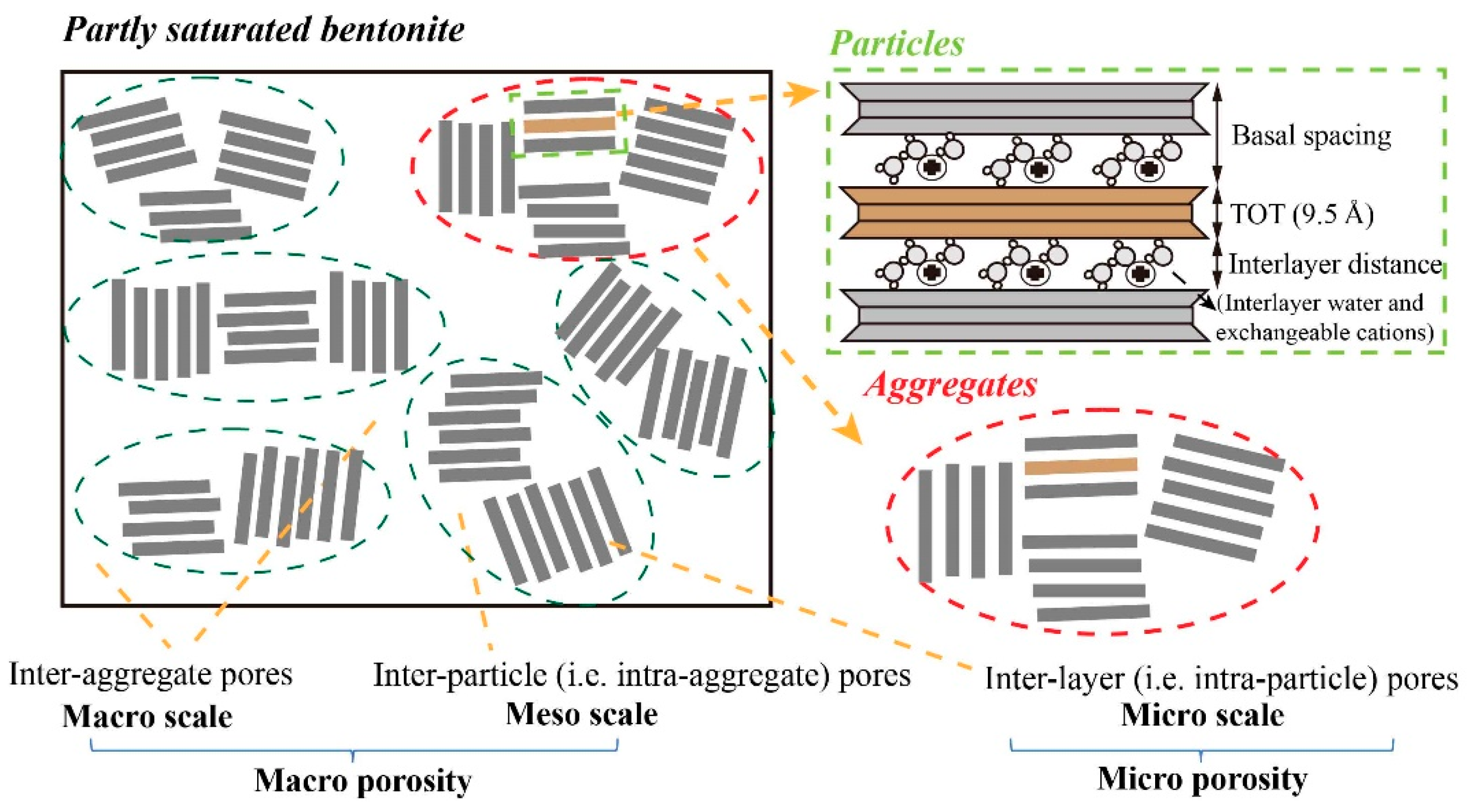
2.1. Pore Evolution of Compacted Bentonite

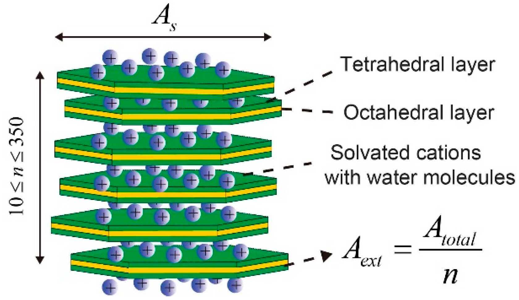
2.1.1. Specific Surface Area

Figure 1 shows a typical lamellar structure of one bentonite particle that consists of 10 to 350 TOT layers (Tetrahedral–Octahedral–Tetrahedral layers). The TOT layers of bentonite are stacked because of repulsive and attractive forces, forming crystal particles. The external surface area (Aext) contributes to overall flux instead of total surface area (Atot). Atot that is independent of water content can be measured by experimental techniques such as Ethylene Glycol Monoethyl Ether. The relationship between Aext and Atot was given as Equation (6) according to the lamellar structure of smectite [50,57,58,59,60],
A e x t = A t o t n
where n is the stacked TOT layers of 1 particle with a range from 10 to 350 depending on water content and the type of bentonite sample.
To estimate the evolution of pore structure, the surface area (As) of a single TOT layer in particles (As) needs to be assessed. The external specific surface area is defined as the external surface of a particle divided by the mass of the particle,
A ext = 2 A s m single
where msingle is the average mass of per particle.
The total number of TOT layers (N) in a bentonite sample is described as Equation (8).
N = m smectite m single n
where m smectite is the mass of smectite (kg).
Therefore, the msingle is expressed as below,
m single = m s m e c t i t e n N
Substituting Equation (9) to Equation (7) yields,
A e x t = 2 A s m s m e c t i t e n / N
Therefore, the combination of Equations (6) and (10) yields As,
A s = m s m e c t i t e A t o t 2 N

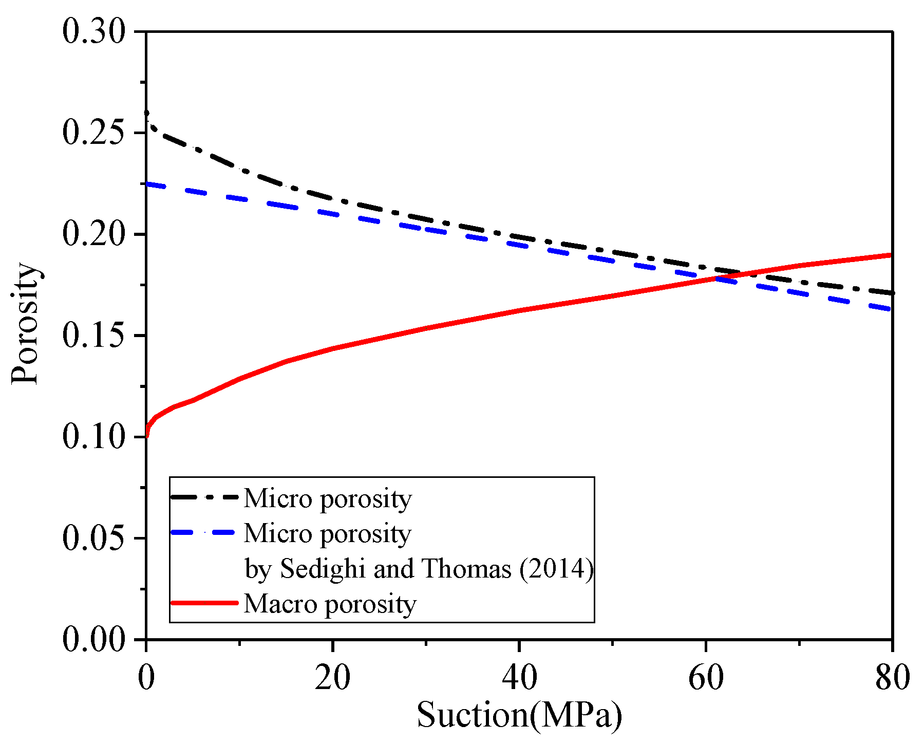
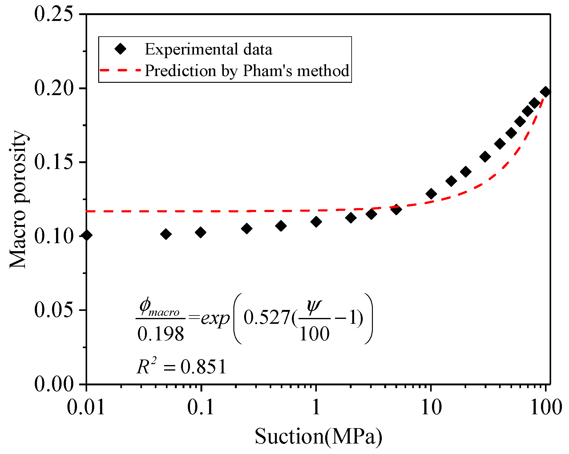
2.1.2. Evolution of Pore System

Figure 2 presents a conceptual diagram of the pore system of compacted bentonite. The microstructure of compacted bentonite is composed of a cluster of TOT layers that constitute bentonite particles and aggregates [52,61]. In many natural porous materials, such as tight rocks or compacted swelling clays, the intraparticle and interparticle pore sizes are in the range of micro (less than 5 nm), meso (between 5 and 50 nm), and macro pores (more than 50 nm) [62]. Several different pore definitions for compacted bentonite were displayed in different publications [19,63,64] where the interlayer pores are identical to intraparticle pores and interparticle pores referred as to intra-aggregate pores. Water flow is constrained in interlayer pores because of interaction between water and the TOT surface of compacted bentonite; therefore it reaches a consensus that the water in interlayer pores is immobile [53,65]. By contrast, water can freely flow through interparticle and interaggregate pores, which contribute to long-range water transport. The interparticle and interaggregate pores are collectively referred to as macro pores, as shown in Figure 2.
In laboratory observations, the number of stacked water layers between two adjacent TOT layers was summarised as one, two, three and even four with higher water content, as shown in Table 1 and Table 2, in which the basal spacing is the summation of the thickness of one TOT layer and thickness of water layers between TOT layers (see the upper-right panel of Figure 2). The four water layers have not been extensively measured and accepted until now, which was found by Saiyouri et al. [66] using MX-80 bentonite. Table 1 shows that the thickness of a single TOT layer is mostly reported as 9.5 Å and the single water layer thickness is 3 Å. The diameter of a water molecule is reported as 3 Å at standard temperature and pressure [67,68], which is identical to the thickness of a single water layer presented in Table 1. Accordingly, the maximal basal spacing is the summation of three water layers and one TOT layer, equal to 18.5 Å, which is consistent with the summary of Table 1.
The adsorption reaction rate of interlayer water is comparable with hydrodynamic adsorption, which is presented by a pseudo-first order kinetic model [73]. Therefore, the evolution of basal spacing against water content is developed based on the hydrodynamic adsorption equation,
d q t d t = k a ( q e q t )
where qe and qt (kg/kg) are the mass of absorbed solute at equilibrium and at time t (h), and ka (h−1) is the rate constant of the pseudo-first order kinetic adsorption. As stated by the boundary conditions (t = 0, qt = 0; t = t, and qt = qt), the integral of the hydrodynamic adsorption equation yields,
q t = q e ( 1 e k a t )
If the water layers are stacked in order then,
( d t d T O T ) = ( d e d T O T ) ( 1 e k a t )
If the water content (ω, kg/kg) is assumed to have a linear relationship with time, then yields,
d t = ( d e d T O T ) ( 1 e b t ) + d T O T
d t = 9 ( 1 e 5.0 ω ) + 9.5 , R 2 = 0.860
where b is a constant correlating with water absorption rate, which is −5.0 obtained by the experimental data (see Figure 3), dTOT and dt are the thickness of a single TOT layer and the basal spacing, respectively, e is natural logarithm.
The water content can be converted into volumetric water content,
θ = V w V t = m w ρ w 1 V t = m s ω ρ w 1 m s ρ d = ρ d ρ w ω
where ms is the mass of solid (kg), mw is the mass of water (kg), ω is the water content (kg/kg), ρw is the density of water (kg/m3), Vt is the total volume of the sample, Vw is the volume of total water in the sample (m3).
In a bentonite particle, the thickness of interlayer water between two TOT layers ( d i w ) can be calculated as follows,
d i w = d t d T O T
The volume of immobile water (namely, the volume of interlayer water, Vimw) can be estimated,
V i m w = A s d i w N = 1 2 d i w A t o t m s s
Consequently, the volume of macro pores (Vmacro) is derived,
V m a c r o = V t V i m w V s
where Vs is the volume of solid.
Therefore, the macro porosity (Φmacro) can be calculated,
ϕ macro = V e V t = 1 V s V t d i w A t o t m s s 2 V t
Accordingly,
ϕ total = 1 ρ d G s
ϕ micro = d i w A t o t ρ d s 2
ϕ macro = 1 ρ d G s d i w A t o t ρ d s 2
where Φmacro is the macro porosity (i.e., effective porosity), Φmicro is the micro porosity (i.e., porosity of interlayer water), ρ d s is the dry density of the smectite (kg/m3), Gs is the specific gravity of soil, ρd is the dry density of the soil (kg/m3).
Bentonite contains impurities (i.e., non-smectite portions), for instance, the GMZ bentonite consisting of 75.4% smectite and 24.6% impurities (11.7% quartz, 7.3% Cristobalite, 4.3% feldspar, 0.8% Kaolinite, 0.5% calcite, etc.) [17]. The dry density of smectite can be derived using Equation (25), if the mass fraction of smectite in the bentonite (Xsm, kg/kg) can be obtained [74],
ρ d s = X s m ρ d [ 1 ( 1 X s m ) ρ d ρ i m ) ] 1
where ρim denotes the density of the non-smectite minerals or impurities (kg/m3).
In summary, the macro porosity only correlates with one unknown variable, i.e., volumetric water content,
ϕ macro = 1 ρ d G s 9 2 A t o t X s m ρ d [ 1 ( 1 X s m ) ρ d ρ i m ) ] 1 ( 1 e 5.0 ρ w ρ d θ )
where ρi is a constant that was recommended 2.8 kg/m3 by literature [52,74].

2.1.3. Tortuosity

Numerous studies have indicated that pore tortuosity serves as a non-negligible factor in determining the hydraulic conductivity of soil [6,35,45,75,76,77,78,79,80]. Pore tortuosity is defined as the ratio of the effective path length (Le) to the sample length (L) [45,81,82],
τ = L e / L
Carman [45] proposed the first derivation of tortuosity as L e / L = s e c α , where α is the angle between the apparent direction of flow and flow pathway for stacked spheres, α is assumed as 45°, thus L e / L equals 2 . Tortuosity of porous media has a logarithmic relationship with porosity, reported as τ 2 = 1 p l n ( ϕ ) , where p is a fitting constant [78,83]. Regarding swelling soils with fine granules and lamellar structures, τ 2 = 1 1 / 2 l n ( ϕ ) given by Weissberg [84] is in line with experimental data [83,84,85].

2.2. Model for Unsaturated Hydraulic Conductivity

In the hypothesis of this work, the saturated hydraulic conductivity of compacted bentonite (ksat) can be derived by taking into account microstructure effects,
k sat = C s γ η ρ d 2 τ 2 A e x t 2 ϕ m a c r o 3 ( 1 ϕ macro ) 2
where γ is the unit weight of the fluid (N/m3) and η is the fluid viscosity (N s/m2) [39,86]. Shape factor (Cs) is reported as 0.2 for soils [33,42,45,87,88].
The unsaturated hydraulic conductivity (kunsat) is the product of relative hydraulic conductivity (kr) and saturated hydraulic conductivity (ksat) [55],
k u n s a t = k r k s a t
The combination of Equations (2)–(5) yields the relative hydraulic conductivity as follows,
k r = ψ ψ d ( 1 / μ + 1 + 3 λ )
and,
k r = S e 3 + 1 + 1 / μ λ
The pore geometry of nonswelling soils is considered a constant whose unsaturated hydraulic conductivity is only impacted by the change of suction. Nevertheless, in reality, the unsaturated hydraulic conductivity of bentonite will be considerably affected by changing hydraulic parameters, such as macro porosity and external specific surface area and tortuosity, caused by the microstructure evolution of the pore network. In early studies, there was a lack of a cutting-edge laboratory device to measure the unsaturated hydraulic conductivity of low-permeability clays such as bentonite. The recent observations showed unsaturated hydraulic conductivity against suction should be a U-shaped curve instead of a monotonically decreasing function [15,89,90]. Therefore, this work considers swelling effects, differing from the traditional constitutive relationship such as Equations (30) and (31) where only suction influences the hydraulic conductivity. If there are swelling effects, a reference point where hydraulic conductivity is equal to fully saturated hydraulic conductivity can be found [23],
k r = k unsat k s a t = k unsat k u n s a t , r e f = k r k r , r e f k sat k s a t , r e f
The combination of Equations (31) and (32) yields,
k r = ( ψ ψ d , r e f ψ d ψ r e f ) ( 1 / μ + 1 + 3 λ ) k s a t k s a t , r e f
The subscript ref denotes the reference point where kunsat,ref equals ksat (namely kr = 1) in the U-shaped curve observed in swelling clays. Ψref is the suction at the reference point. All the corresponding kunsat,ref, Ψref and Φref are the values at the same reference point. One example can be found for Na-bentonite Kunigel-V1 in Cui et al. [15], where the suction is 35 MPa and corresponding kr = 1 as the reference point used by Liu et al. [23].
The expansive capability results in the decrease of macro porosity. Leverett [91] proposed that the change of air entry value (Ψd) can be represented by a function of porosity under confined condition. Therefore, Liu et al. [23] deduced Equations (34) and (35) to establish the relationship of Ψd and air entry value at the reference point (Ψd,ref) under the confined condition as below,
ψ d , ref ψ d = ϕ ϕ r e f
k sat k s a t , ref = ( ϕ ϕ r e f ) ( 1 + 1 / μ ) σ
where parameter σ is larger than one for swelling materials because the porosity may not reflect the effect of well-connected pores on hydraulic conductivity.
Substituting Equations (34) and (35) into Equation (33) yields,
k r = ψ ψ r e f ( 1 / μ + 1 + 3 λ ) ( ϕ ϕ r e f ) ( σ 1 ) ( 1 + 1 / μ ) 3 λ
Comparing Equation (36) with Equations (34) and (35), the revised model introduces one more factor related to porosity, i.e., ( ϕ / ϕ r e f ) σ 1 1 + 1 / μ 3 λ which represents the expansive capability of clayey soil under constant-volume condition, and ( ψ / ψ r e f , c ) 1 / μ + 1 + 3 λ reflects the change of hydraulic conductivity resulting from declining suction.
Pham et al. [92] reported that the swelling capability of clays was an exponential function of suction under confined condition,
ϕ ϕ r e f = exp β ( ψ ψ r e f 1 )
where β is a fitting factor.
The combination of Equations (36) and (37) yields the constitutive relationship of unsaturated swelling clays as below,
k r = ψ ψ r e f ( 1 / μ + 1 + 3 λ ) exp ( ψ ψ r e f 1 ) β [ ( σ 1 ) ( 1 + 1 / μ ) 3 λ ]
where the experimental data reported in Cui et al. [15] support that μ equals 0.28 as a constant with various suction; β can be derived by Equation (37), while The σ and λ can be found using experimental data.

3. Results and Discussion

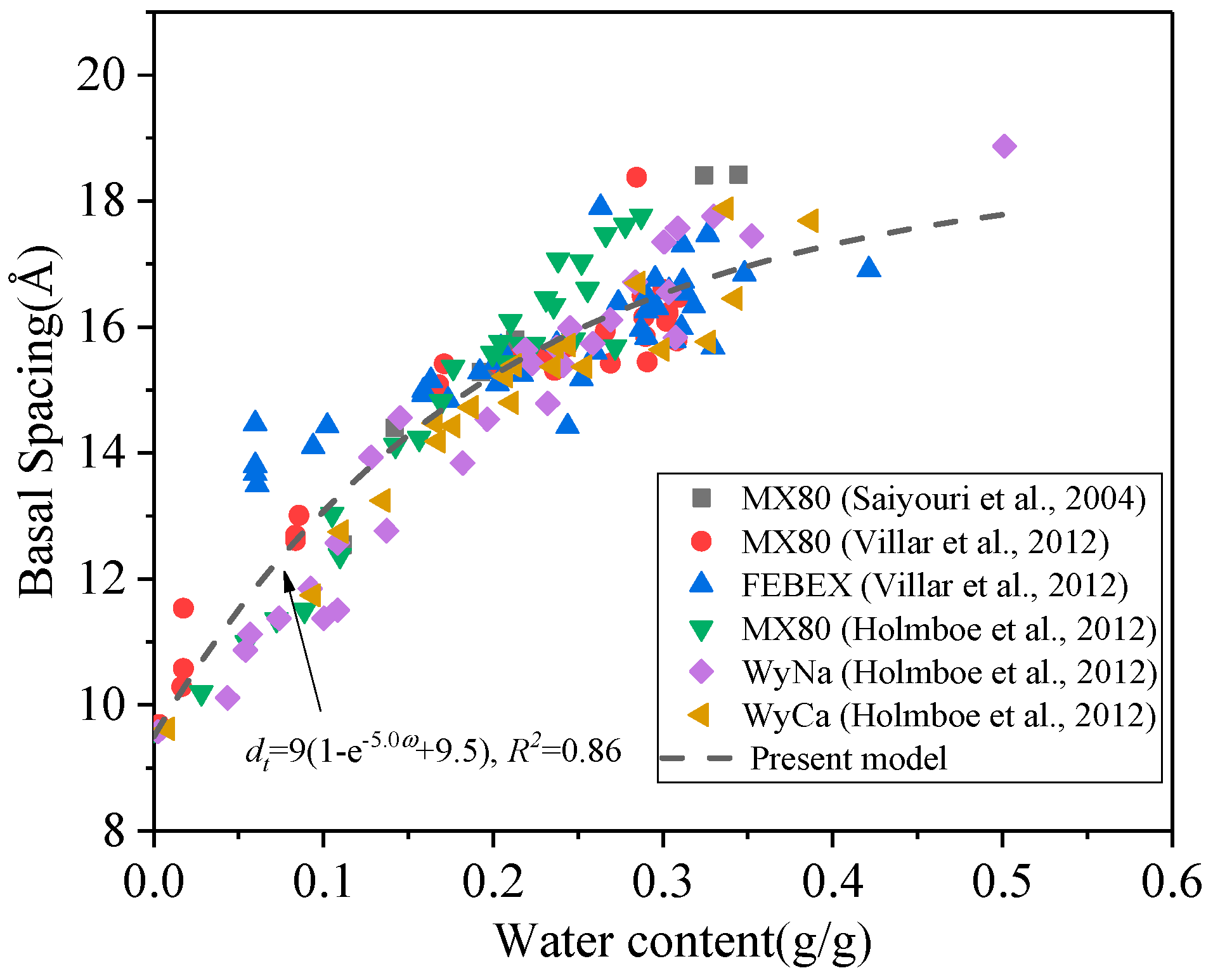
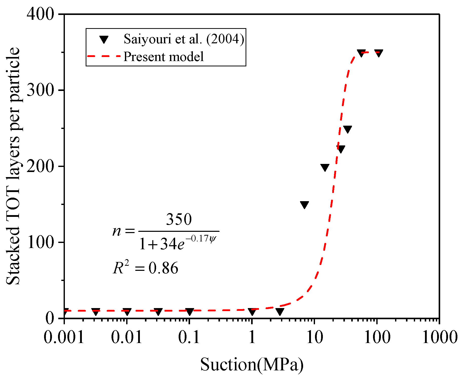
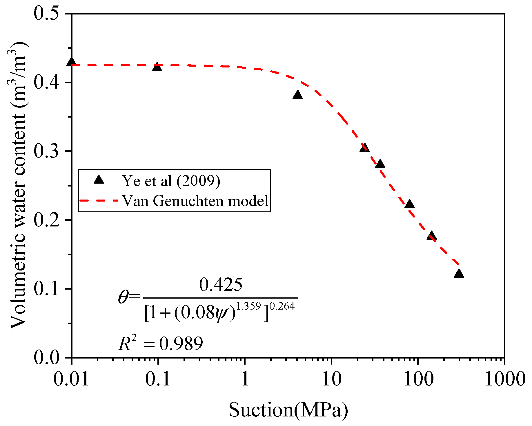
3.1. Experimental Data and Parameters of Model

In the work, the experimental materials are employed to verify the theoretical model including Na-bentonite GMZ and MX80 whose properties are listed in Table 3.
External specific surface area is the first parameter estimated to derive the saturated hydraulic conductivity based on the revised Kozeny–Carman equation. The experimental data of stacked TOT layers per particle were measured by Saiyouri et al. [66]. A fit to the data was proposed by Chen et al (2020), showing a good match,
n = n max ( 1 + ( n max / n min 1 ) e c ψ )
where nmax and nmin are the maximum and minimum stacked TOT layers per particle with 10 and 350, respectively, given by Saiyouri et al. [66], and c is a dimensionless fitting parameter that is equal to −0.17 for Na-bentonite according to Figure 4 and is associated with the reaction rate between water and bentonite.
Consequently, the external specific area can be illustrated,
A e x t = A t o t n c = 570 350 / ( 1 + 34 e 0.17 ψ )
To derive macro porosity (effective porosity), the data from Table 3 are substituted into Equation (26), and the results are shown in Figure 5 (the red line). To evaluate its accuracy, this work compares with the theoretical method of micro porosity proposed by Sedighi and Thomas [52] as Equation (41),
ϕ m i c r o = X h s ζ c υ i l M s m ρ d s
where Xhs denotes the mole fraction of hydrated smectite, which can be gained from Sedighi and Thomas [52]; Msm is the molar mass of dry smectite (kg/mol), given as 378.787 kg/mol by Gailhanou et al. [94]; ζc is the number of moles of water in the interlayer adsorption or desorption reaction, reported as 4.5 mol of water, if a maximum of two monolayers of adsorbed water occurs in the interlayer pores [52]; and υil is the molar volume of the interlayer water, recommended as 17.22 m3/mol [95].
The outcomes from the two presented methods are compatible for compacted MX-80 bentonite. However, the proposed method has an advantage in feasibility compared with the geochemical model proposed by Sedighi and Thomas [52] because of fewer assumptions during the process of derivation. Moreover, in comparison with two water layers between TOT layers in Sedighi and Thomas [52], this present method takes into account three water layers that are closer to the recent experimental observation for Na-bentonite.
Figure 5 shows the Φmicro increases with a decrease in suction and finally approaches stable at 0.260, while the Φmacro drops before stable at 0.101. In the fully saturated condition, Φmicro is 2.6 times higher than Φmacro that only makes up 27.9% of the total porosity (0.361). As a summary, as fewer than 30% of pores are macro pores that contribute to long-term water flow, the traditional KC equation using total porosity will largely overestimate the saturated hydraulic conductivity of bentonite. Secondly, the difference between macro porosity and total porosity explains clayey soils such as bentonite with a large porosity but much lower permeability compacted with nonexpansive soils. Thirdly, the transfer from Φmacro to Φmicro over a large range of suction gives rise to a decrease of unsaturated hydraulic conductivity, and as stated above, Φmicro makes no contribution to long-range water transport.

3.2. Saturated Hydraulic Conductivity

Since only macro pores contribute to water flow in compacted bentonite, the total porosity in the Kozeny–Carman equation is replaced by the macro parameter that includes external specific surface area, macro porosity and tortuosity. These macro parameters change with the swelling microstructure of compacted bentonite in the wetting path:
k sat = C s γ η ρ m 2 τ macro 2 A e x t 2 ϕ macro 3 ( 1 ϕ macro ) 2
The variables or constants from Table 3 are substituted to Equation (42), which yields that ksat of GMZ equals 1.01 × 10⁻¹³ (m/s). Based on the macro porosity derived from Sedighi and Thomas [52], the ksat of GMZ is 1.88 × 10⁻¹³ (m/s), whereas the experimental result of ksat is 1.18 × 10⁻¹³ [14]. The calculated results fall within the range from 1/3 to 3 times of experimental values, which are regarded as acceptable outcomes because of the uncertainty of experimental hydraulic conductivity [28,33,86,87,96]. In summary, both methods achieve reliable results of estimated saturated hydraulic conductivity that fall within the acceptable experimental range, whereas the predictive results of the present method are closer to experimentally measured values.

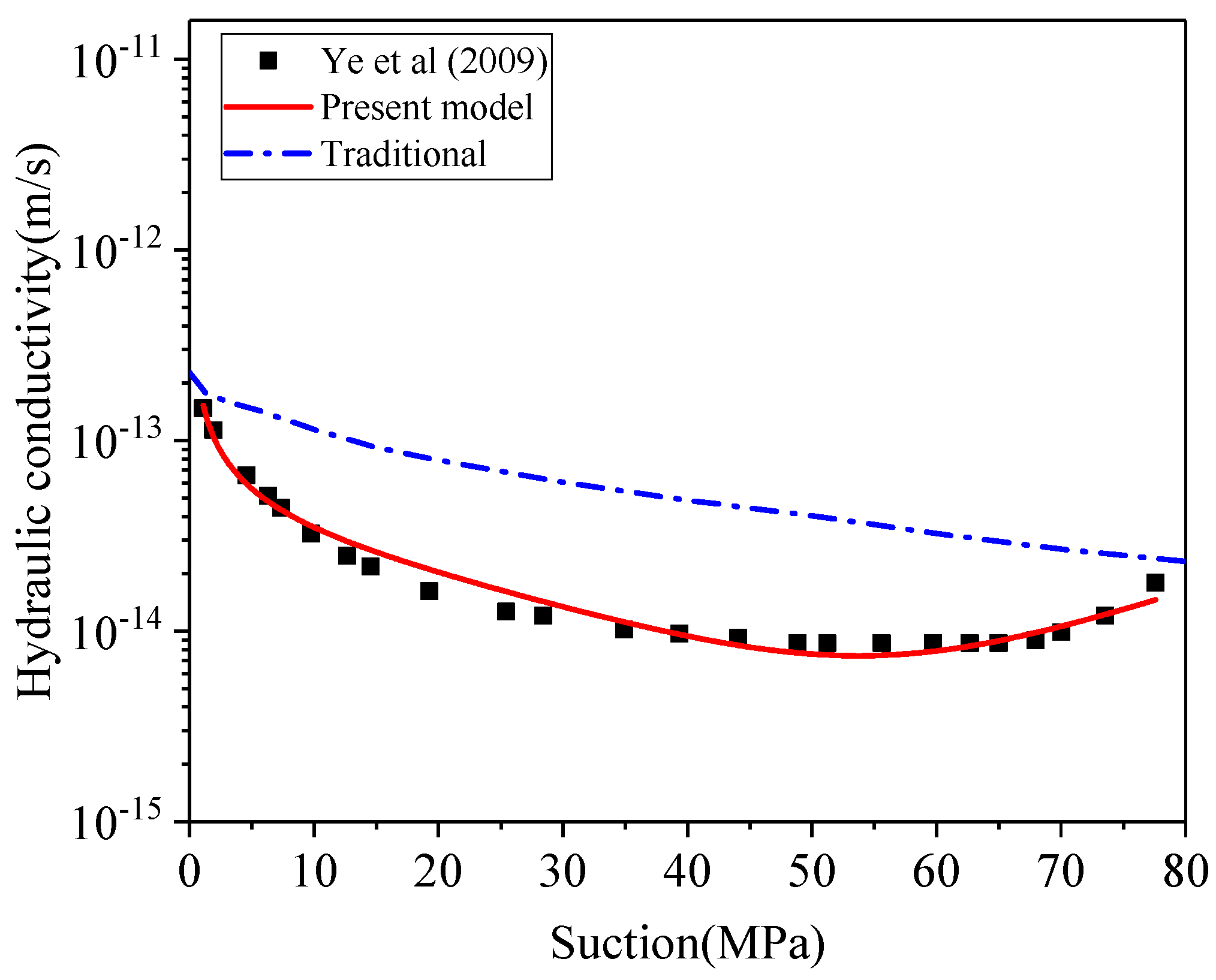
3.3. Unsaturated Hydraulic Conductivity

In this section, the relative hydraulic conductivity ( k r * ) of Na-bentonite including GMZ bentonite and MX80 bentonite is discussed in order to predict the unsaturated hydraulic conductivity. The reference point where kunsat = ksat has not been found for GMZ bentonite by experiments (Ye et al., 2009); however, it can be estimated that when suction is approaching 100 MPa (Ψref), kunsat equals ksat, based on the trend of experimental hydraulic conductivity. Since the suction can be presented by volumetric water content according to van Genuchten [24], the macro porosity is derived using the volumetric water content through Equation (26). As van Genuchten [24] reported, the θr of clayey soil can be regarded as zero, and the θs of GMZ is 0.425 (m3/m3) derived from experimental data of Ye et al. [14]. The fitting parameters “a” and “m” can be acquired from Figure 6:
θ = θ s θ r [ 1 + ( a ψ ) 1 / ( 1 m ) ] m + θ r
θ = 0.425 [ 1 + ( 0.08 ψ ) 1.359 ] 0.264
Consequently, when suction is 100 MPa (Ψref), the θref is corresponding to 0.209. The combination of Equations (37) and (44) yields Φref as 0.198. Therefore,
ϕ macro 0.198 = exp β ( ψ 100 1 )
where β is estimated as 0.537 from Figure 7.
Since the Ψref (100 MPa) is obtained by extending the trend of the experimental curve, it could be slightly different from the real value of Ψref; therefore, a small correction term (C × Ψ/Ψref) is introduced into Equation (38), yielding Equation (46), which reduces the deviation caused by the assumed Ψref. If Ψref can be measured accurately, the small correction term can be considered as zero, which has been proved by Liu et al. [23]. In summary, the C can be understood as a factor to express the relative error between the estimated Ψref and the actual Ψref:
k r = ψ ψ ref ( 1 / μ + 1 + 3 λ ) exp ( ψ ψ r e f 1 ) β [ ( σ 1 ) ( 1 + 1 / μ ) 3 λ ] + C ψ ψ r e f
k u n s a t = k s a t k r = k s a t [ ψ ψ r e f ( 1 / μ + 1 + 3 λ ) exp ( ψ ψ r e f 1 ) β [ ( σ 1 ) ( 1 + 1 / μ ) 3 λ ] + C ψ ψ r e f ]
When the experimental data from Ye et al. [14] are substituted into the constitutive model, the λ, σ and C are equal to −1.29, 1.318, −0.64 as shown in Equation (48). From the predicted curve of Figure 8, the degree of correlation between experimental data and prediction is 99.0%, which shows the high accuracy of the theoretical model on kunsat.
k u n s a t = 1.1 × 10 13 [ ψ 100 0.70 exp 2.86 ( ψ 100 1 ) 0.64 ψ 100 ]
This model is also verified to predict kunsat using the MX80 bentonite measured by Wang et al. [90]. As shown in Figure 9, the results confirm that the present model can precisely predict the kunsat of MX80 with a degree of correlation as 99.3%.
k u n s a t = 1 × 10 13 [ ( ψ 70 ) 0.46 exp 2.77 ( ψ 70 1 ) 0.1 ψ 70 ]
The proposed constitutive relationship incorporates the effect of microstructural expansion on the evolution of unsaturated hydraulic conductivity. The outcome of the proposed model is in line with the experimental measurement for both bentonites. The traditional approach (Equations (30) and (31)), which ignores the microstructure effects, yields much higher prediction and is not able to explain the decrease of hydraulic conductivity with declining suction. This developed constitutive relationship can well describe water flow in swelling bentonite that has the U-shaped hydraulic conductivity. This proposed relationship reveals that macro pores (Φmacro) continue to convert into micro pores (Φmicro), and the average pore size of bentonite decreases over wetting path (dropping suction) of compacted bentonite, resulting in a drop of hydraulic conductivity. Subsequently, the hydraulic conductivity is dominated by the gradient of suction, showing an increasing trend in the low suction range. As a summary, the predictive outcomes of the new constitutive relationship show an excellent match with laboratory observation of unsaturated hydraulic conductivity, while the traditional approach overestimates the hydraulic conductivity without consideration of microstructure effect.

4. Summary and Conclusions

This work aims to develop a new constitutive relationship for unsaturated hydraulic conductivity of compacted bentonite, including the microstructure effect. The microstructure effect is represented by the change of accessible porosity (i.e., macro porosity) for water, further resulting in a varying tortuosity, specific surface area and relative hydraulic conductivity. The modified Kozeny–Carman equation was developed for saturated hydraulic conductivity incorporating the microstructure evolution, yielding a good agreement with experimental results. Furthermore, a new constitutive relationship for relative hydraulic conductivity was developed, including both effects of capillary pressure and microstructural expansions during wetting path. The prediction of the new constitutive relationship is in excellent accord with the laboratory observation for GMZ and MX80 bentonite over the entire wetting path, explaining the initial decrease of hydraulic conductivity with declining suction (i.e., U-shaped curve) for compacted bentonite. The traditional model ignores microstructure expansion, leading to an overestimation of hydraulic conductivity and failure in explanation of decrease of hydraulic conductivity in the early stage of wetting path. This work helps improve the understanding of accurate prediction of flow process in the environmental application of swelling clays, including containment systems, especially in the geological disposal of high-level nuclear waste.

Author Contributions

Conceptualisation, T.C. and M.D.; formal analysis, T.C., M.D. and Q.Y.; investigation, T.C., M.D. and Q.Y.; writing—original draft, T.C. and M.D.; writing—review and editing, Q.Y.; project administration, M.D. and Q.Y. All authors have read and agreed to the published version of the manuscript.

Funding

Qiangling Yao thanks the National Natural Science Foundation of China (51874283) for support.

Institutional Review Board Statement

Not applicable.

Informed Consent Statement

Not applicable.

Data Availability Statement

All data, models, or code that support the findings of this study are available from the corresponding author.

Acknowledgments

Tian Chen appreciates the support of the President’s Doctoral Scholarship and the supervisory team from the University of Manchester.

Conflicts of Interest

The authors declare no conflict of interest.

Abbreviations

kHydraulic permeability (m/s)
krRelative hydraulic conductivity
k r * Proposed relative hydraulic conductivity of compacted bentonite
ksatThe saturated hydraulic conductivity (m/s)
kunsatThe unsaturated hydraulic conductivity (m/s)
SeThe effective saturation
θThe actual volumetric water content
θrThe residual volumetric water content
θsThe saturated volumetric water content
αThe constant parameter in Mualem [54]
μA dimensionless number in Burdine [31]
ΨSuction of soil/bentonite(MPa)
ΨdThe air entry value (MPa)
λA fitting factor related to pore-size distribution
CsShape factor
τTortuosity
γwUnit weight of water (N/m3)
ηViscosity of water (Pa∙s)
SASpecific surface area (m2/kg)
ΦPorosity
ρdDry density of soil (kg/m3)
AtotTotal specific surface area (m2/kg)
nThe number of TOT layers of per particle
NTotal number of TOT layers of bentonite sample
AextExternal specific surface area of bentonite (m2/g)
AsThe surface area of a single TOT layer
msiMass of one particle (kg)
msmectiteMass of smectite (kg)
msMass of solid (kg)
b
C
A constant related to water adsorption rate
A correction term
ωWater content (kg/kg)
ρwDensity of water (kg/m3)
mwThe mass of water (kg)
VtTotal volume of soil sample (m3)
VwVolume of total water in soil (m3)
ρ d s Dry density of smectite (kg/m3)
dTOTThickness of TOT layer (9.5 Å)
dtBasal spacing (Å)
hwTotal interlayer water thickness of soil
VimwMicro pore volume/volume of interlayer water
VeMacro pore volume/effect pore volume
VsVolume of solid (m3)
diwInterlayer water thickness between two TOT layers
ΦmacroMacro porosity (Effective porosity)
ΦmicroMicro porosity (Interlayer porosity)
ρsDensity of the solid (kg/m3)
ρiDensity of the non-smectite minerals or impurities (kg/m3)
GsSpecific gravity of clay
XsmThe mass fraction of smectite in the bentonite
LeEffective path length of flow
LSample length
refThe reference case in which measurements are available
βA fitting factor between Φ and Ψ in Pham et al. [92]
σCoefficient related to porosity and size of pore
XhsMole fraction of hydrated smectite
MsmMolar mass of dry smectite (Kg/mol)
ζcThe number of moles of waters in the interlayer adsorption or desorption reaction
υilThe molar volume of the interlayer water (m3/mol)
a, mCurve-fitting parameters by van Genuchten [24]
nmax, nminThe maximum and minimum number of TOT layers of bentonite particle respectively

References

  1. Pusch, R.; Yong, R.N. Microstructure of Smectite Clays and Engineering Performance; Taylor and Francis: New York, NY, USA, 2006. [Google Scholar]
  2. Kohler, M.; Curtis, G.P.; Kent, D.; Davis, J.A. Experimental Investigation and Modeling of Uranium (VI) Transport Under Variable Chemical Conditions. Water Resour. Res. 1996, 32, 3539–3551. [Google Scholar] [CrossRef]
  3. Xiong, Q.; Joseph, C.; Schmeide, K.; Jivkov, A.P. Measurement and modelling of reactive transport in geological barriers for nuclear waste containment. Phys. Chem. Chem. Phys. 2015, 17, 30577–30589. [Google Scholar] [CrossRef] [Green Version]
  4. Gleason, M.H.; Daniel, D.E.; Eykholt, G.R. Calcium and Sodium Bentonite for Hydraulic Containment Applications. J. Geotech. Geoenviron. Eng. 1997, 123, 438–445. [Google Scholar] [CrossRef]
  5. Yigzaw, Z.G.; Cuisinier, O.; Massat, L.; Masrouri, F. Role of different suction components on swelling behavior of compacted bentonites. Appl. Clay Sci. 2016, 120, 81–90. [Google Scholar] [CrossRef]
  6. Bouchelaghem, F.; Pusch, R. Fluid flow and effective conductivity calculations on numerical images of bentonite microstructure. Appl. Clay Sci. 2017, 144, 9–18. [Google Scholar] [CrossRef] [Green Version]
  7. Busch, A.; Alles, S.; Gensterblum, Y.; Prinz, D.; Dewhurst, D.N.; Raven, M.D.; Stanjek, H.; Krooss, B. M Carbon dioxide storage potential of shales. Int. J. Greenh. Gas Control. 2008, 2, 297–308. [Google Scholar] [CrossRef]
  8. Blunt, M.J.; Bijeljic, B.; Dong, H.; Gharbi, O.; Iglauer, S.; Mostaghimi, P.; Paluszny, A.; Pentland, C. Pore-scale imaging and modelling. Adv. Water Resour. 2013, 51, 197–216. [Google Scholar] [CrossRef] [Green Version]
  9. Ezeuko, C.; Sen, A.; Grigoryan, A.; Gates, I. Pore-network modeling of biofilm evolution in porous media. Biotechnol. Bioeng. 2011, 108, 2413–2423. [Google Scholar] [CrossRef]
  10. Chung, E.T.; Efendiev, Y.; Leung, T.; Vasilyeva, M. Coupling of multiscale and multi-continuum approaches. GEM Int. J. Geomath. 2017, 8, 9–41. [Google Scholar] [CrossRef] [Green Version]
  11. Mather, J.; Chapman, N.; Black, J.; Lintern, B. The geological disposal of high-level radioactive waste-a review of the Institute of Geological Sciences’ research programme. Nucl. Energy 1982, 21, 167–173. [Google Scholar]
  12. Kutalek, R.; Wewalka, G.; Gundacker, C.; Auer, H.; Wilson, J.; Haluza, D.; Huhulescu, S.; Hillier, S.; Sager, M.; Prinz, A. Geophagy and potential health implications: Geohelminths, microbes and heavy metals. Trans. R. Soc. Trop. Med. Hyg. 2010, 104, 787–795. [Google Scholar] [CrossRef]
  13. Eisenhour, D.D.; Brown, R.K. Bentonite and its impact on modern life. Elements 2009, 5, 83–88. [Google Scholar] [CrossRef]
  14. Ye, W.; Cui, Y.; Qian, L.; Chen, B. An experimental study of the water transfer through confined compacted GMZ bentonite. Eng. Geol. 2009, 108, 169–176. [Google Scholar] [CrossRef] [Green Version]
  15. Cui, Y.; Tang, A.M.; Loiseau, C.; Delage, P. Determining the unsaturated hydraulic conductivity of a compacted sand–bentonite mixture under constant-volume and free-swell conditions. Phys. Chem. Earth Parts A/B/C 2008, 33, S462–S471. [Google Scholar] [CrossRef] [Green Version]
  16. Cui, Y.-J.; Tang, A.M.; Qian, L.-X.; Ye, W.-M.; Chen, B. Thermal-Mechanical Behavior of Compacted GMZ Bentonite. Soils Found. 2011, 51, 1065–1074. [Google Scholar] [CrossRef] [Green Version]
  17. Ye, W.; Borrell, N.; Zhu, J.; Chen, B.; Chen, Y. Advances on the investigation of the hydraulic behavior of compacted GMZ bentonite. Eng. Geol. 2013, 169, 41–49. [Google Scholar] [CrossRef]
  18. Ye, W.; Zheng, Z.; Chen, B.; Chen, Y.; Cui, Y.; Wang, J. Effects of pH and temperature on the swelling pressure and hydraulic conductivity of compacted GMZ01 bentonite. Appl. Clay Sci. 2014, 101, 192–198. [Google Scholar] [CrossRef]
  19. Xiong, Q.; Baychev, T.G.; Jivkov, A.P. Review of pore network modelling of porous media: Experimental characterisations, network constructions and applications to reactive transport. J. Contam. Hydrol. 2016, 192, 101–117. [Google Scholar] [CrossRef]
  20. Delage, P. Micro-Macro Effects in Bentonite Engineered Barriers for Radioactive Waste Disposal. In Proceedings of the 8th International Congress on Environmental Geotechnics, Hangzhou, China, 28 October–1 November 2019; Springer: Singapore, 2019; Volume 1, pp. 61–80. [Google Scholar]
  21. Sedighi, M.; Thomas, H.R.; Vardon, P.J. Reactive Transport of Chemicals in Compacted Bentonite under Nonisothermal Water Infiltration. J. Geotech. Geoenviron. Eng. 2018, 144, 04018075. [Google Scholar] [CrossRef] [Green Version]
  22. Thomas, H.; Cleall, P.; Chandler, N.; Dixon, D.; Mitchell, H. Water infiltration into a large-scale in-situ experiment in an underground research laboratory. Géotechnique 2003, 53, 207–224. [Google Scholar] [CrossRef]
  23. Liu, H.-H.; Li, L.; Birkholzer, J. Unsaturated properties for non-Darcian water flow in clay. J. Hydrol. 2012, 430–431, 173–178. [Google Scholar] [CrossRef] [Green Version]
  24. van Genuchten, M.T. A Closed-form Equation for Predicting the Hydraulic Conductivity of Unsaturated Soils. Soil Sci. Soc. Am. J. 1980, 44, 892–898. [Google Scholar] [CrossRef] [Green Version]
  25. Agus, S.; Schanz, T. In Permeability of a heavily compacted bentonite-sand mixture as sealing and buffer element for nuclear waste repository, Unsaturated Soils. In Advances in Geo-Engineering, Proceedings of the 1st European Conference, Durham, UK, 2–4 July 2008; CRC Press: Durham, UK, 2008; pp. 305–311. [Google Scholar]
  26. Agus, S.; Leong, E.; Schanz, T. Assessment of statistical models for indirect determination of permeability functions from soil–water characteristic curves. Géotechnique 2003, 53, 279–282. [Google Scholar] [CrossRef]
  27. van Genuchten, M.T.; Nielsen, D.C. On describing and predicting the hydraulic properties. Annales Geophysicae 1985, 3, 615–628. [Google Scholar]
  28. Chapuis, R.P. Predicting the saturated hydraulic conductivity of soils: A review. Bull. Eng. Geol. Environ. 2012, 71, 401–434. [Google Scholar] [CrossRef]
  29. Guo, Y.; Pan, B.; Zhang, L.; Fang, C. A new model to predict the relative permeability of wetting phase for tight sandstones. Environ. Fluid Mech. 2017, 17, 1067–1079. [Google Scholar] [CrossRef]
  30. Chapuis, R.P.; Suits, L.D.; Likos, W.J. Compacted Clay: Difficulties Obtaining Good Laboratory Permeability Tests. Geotech. Test. J. 2017, 40, 20150286. [Google Scholar] [CrossRef]
  31. Burdine, N. Relative Permeability Calculations from Pore Size Distribution Data. J. Pet. Technol. 1953, 5, 71–78. [Google Scholar] [CrossRef]
  32. Chen, T.; Sedighi, M.; Jivkov, A.; Seetharam, S. A model for hydraulic conductivity of compacted bentonite—Inclusion of microstructure effects under confined wetting. Géotechnique 2020, 71, 1–14. [Google Scholar] [CrossRef] [Green Version]
  33. Ren, X.; Zhao, Y.; Deng, Q.; Kang, J.; Li, D.; Wang, D. A relation of hydraulic conductivity—Void ratio for soils based on Kozeny-Carman equation. Eng. Geol. 2016, 213, 89–97. [Google Scholar] [CrossRef]
  34. Yustres, Á.; López-Vizcaíno, R.; Sáez, C.; Cañizares, P.; Rodrigo, M.A.; Navarro, V. Water transport in electrokinetic remediation of unsaturated kaolinite. Experimental and numerical study. Sep. Purif. Technol. 2018, 192, 196–204. [Google Scholar] [CrossRef]
  35. Srisutthiyakorn, N.; Mavko, G.M. What is the role of tortuosity in the Kozeny-Carman equation? Interpretation 2017, 5, SB57–SB67. [Google Scholar] [CrossRef]
  36. Katagiri, J.; Konno, Y.; Yoneda, J.; Temma, N. Pore-scale modeling of flow in particle packs containing grain-coating and pore-filling hydrates: Verification of a Kozeny–Carman-based permeability reduction model. J. Nat. Gas Sci. Eng. 2017, 45, 537–551. [Google Scholar] [CrossRef]
  37. Hilfer, R. Geometric and dielectric characterization of porous media. Phys. Rev. B 1991, 44, 60–75. [Google Scholar] [CrossRef] [PubMed] [Green Version]
  38. Zakirov, T.; Khramchenkov, M. Prediction of permeability and tortuosity in heterogeneous porous media using a disorder parameter. Chem. Eng. Sci. 2020, 227, 115893. [Google Scholar] [CrossRef]
  39. Carrier, W.D., III. Goodbye, hazen; hello, kozeny-carman. J. Geotech. Geoenviron. Eng. 2003, 129, 1054–1056. [Google Scholar] [CrossRef]
  40. Bourg, I.C.; Ajo-Franklin, J.B. Clay, Water, and Salt: Controls on the Permeability of Fine-Grained Sedimentary Rocks. Accounts Chem. Res. 2017, 50, 2067–2074. [Google Scholar] [CrossRef] [PubMed]
  41. Xu, H.; Zhu, W.; Qian, X.; Wang, S.; Fan, X. Studies on hydraulic conductivity and compressibility of backfills for soil-bentonite cutoff walls. Appl. Clay Sci. 2016, 132–133, 326–335. [Google Scholar] [CrossRef]
  42. Taylor, D.W. Fundamentals of Soil Mechanics; Chapman and Hall, Limited: New York, NY, USA, 1948. [Google Scholar]
  43. Molinero-Guerra, A.; Delage, P.; Cui, Y.-J.; Mokni, N.; Tang, A.M.; Aimedieu, P.; Bernier, F.; Bornert, M. Water-retention properties and microstructure changes of a bentonite pellet upon wetting/drying; application to radioactive waste disposal. Géotechnique 2020, 70, 199–209. [Google Scholar] [CrossRef]
  44. Kozeny, J. Uber kapillare leitung der wasser in boden. R. Acad. Sci. Vienna Proc. Class. I 1927, 136, 271–306. [Google Scholar]
  45. Carman, P.C. Fluid flow through granular beds. Chem. Eng. Res. Des. 1997, 75, S32–S48. [Google Scholar] [CrossRef]
  46. Carman, P.C. Flow of Gases through Porous Media; Butterworths Publications Ltd.: London, UK, 1956. [Google Scholar]
  47. Chapuis, R.P.; Aubertin, M. On the use of the Kozeny–Carman equation to predict the hydraulic conductivity of soils. Can. Geotech. J. 2003, 40, 616–628. [Google Scholar] [CrossRef]
  48. Chapuis, R.; Légaré, P.-P. A simple method for determining the surface area of fine aggregates and fillers in bituminous mixtures. In Effects of Aggregates and Mineral Fillers on Asphalt Mixture Performance; American Society for Testing and Materials: Philadelphia, PA, USA, 1992; pp. 177–186. [Google Scholar]
  49. Holmboe, M.; Wold, S.; Jonsson, M. Porosity investigation of compacted bentonite using XRD profile modeling. J. Contam. Hydrol. 2012, 128, 19–32. [Google Scholar] [CrossRef]
  50. Tournassat, C.; Bizi, M.; Braibant, G.; Crouzet, C. Influence of montmorillonite tactoid size on Na–Ca cation exchange reactions. J. Colloid Interface Sci. 2011, 364, 443–454. [Google Scholar] [CrossRef] [PubMed] [Green Version]
  51. Likos, W.J.; Wayllace, A. Porosity evolution of free and confined bentonites during interlayer hydration. Clays Clay Miner. 2010, 58, 399–414. [Google Scholar] [CrossRef]
  52. Sedighi, M.; Thomas, H.R. Micro porosity evolution in compacted swelling clays—A chemical approach. Appl. Clay Sci. 2014, 101, 608–618. [Google Scholar] [CrossRef]
  53. Bradbury, M.H.; Baeyens, B. Porewater chemistry in compacted re-saturated MX-80 bentonite. J. Contam. Hydrol. 2003, 61, 329–338. [Google Scholar] [CrossRef]
  54. Mualem, Y. A new model for predicting the hydraulic conductivity of unsaturated porous media. Water Resour. Res. 1976, 12, 513–522. [Google Scholar] [CrossRef] [Green Version]
  55. Brooks, R.; Corey, T. Hydraulic Properties of Porous Media; Hydrology Papers; Colorado State University: Fort Collins, CO, USA, 1964. [Google Scholar]
  56. Averyanov, S.F. About Permeability of Subsurface Soils in Case of Incomplete Saturation; English Collection Volume 7; The Theory of Ground Water Movement; Princeton University Press: Princeton, NJ, USA, 1950. [Google Scholar]
  57. Cases, J.M.; Berend, I.; Besson, G.; Francois, M.; Uriot, J.P.; Thomas, F.; Poirier, J.E. Mechanism of adsorption and desorption of water vapor by homoionic montmorillonite. 1. The sodium-exchanged form. Langmuir 1992, 8, 2730–2739. [Google Scholar] [CrossRef]
  58. Jacinto, A.; Villar, M.V.; Ledesma, A. Influence of water density on the water-retention curve of expansive clays. Geotechnique 2012, 62, 657–667. [Google Scholar] [CrossRef]
  59. Perdrial, J.; Warr, L.N. Hydration Behavior of MX80 Bentonite in a Confined-Volume System: Implications for Backfill Design. Clays Clay Miner. 2011, 59, 640–653. [Google Scholar] [CrossRef]
  60. Cases, J.; Bérend, I.; François, M.; Uriot, J.; Michot, L.; Thomas, F. Mechanism of adsorption and desorption of water vapor by homoionic montmorillonite; 3, The Mg (super 2+), Ca (super 2+), and Ba (super 3+) exchanged forms. Clays Clay Miner. 1997, 45, 8–22. [Google Scholar] [CrossRef]
  61. Zhu, C.-M.; Ye, W.-M.; Chen, Y.; Chen, B.; Cui, Y.-J. Influence of salt solutions on the swelling pressure and hydraulic conductivity of compacted GMZ01 bentonite. Eng. Geol. 2013, 166, 74–80. [Google Scholar] [CrossRef]
  62. Salles, F.; Douillard, J.-M.; Denoyel, R.; Bildstein, O.; Jullien, M.; Beurroies, I.; Van Damme, H. Hydration sequence of swelling clays: Evolutions of specific surface area and hydration energy. J. Colloid Interface Sci. 2009, 333, 510–522. [Google Scholar] [CrossRef] [PubMed]
  63. Pusch, R. Bentonite Clay: Environmental Properties and Applications; CRC Press: New York, NY, USA, 2015. [Google Scholar]
  64. Gens, A. Soil–environment interactions in geotechnical engineering. Géotechnique 2010, 60, 3–74. [Google Scholar] [CrossRef]
  65. Wersin, P.; Curti, E.; Appelo, C. Modelling bentonite–water interactions at high solid/liquid ratios: Swelling and diffuse double layer effects. Appl. Clay Sci. 2004, 26, 249–257. [Google Scholar] [CrossRef]
  66. Saiyouri, N.; Tessier, D.; Hicher, P.Y. Experimental study of swelling in unsaturated compacted clays. Clay Miner. 2004, 39, 469–479. [Google Scholar] [CrossRef] [Green Version]
  67. Hillel, D. Introduction to Environmental Soil Physics; Academic Press, Elsevier Science: San Diego, CA, USA, 2003. [Google Scholar]
  68. Singh, P.N.; Wallender, W.W. Effects of Adsorbed Water Layer in Predicting Saturated Hydraulic Conductivity for Clays with Kozeny–Carman Equation. J. Geotech. Geoenviron. Eng. 2008, 134, 829–836. [Google Scholar] [CrossRef]
  69. Jacinto, A.C.; Ledesma, A.; Demagistri, A. Effect of the clay–water interaction in the hydration of compacted bentonite used in engineered barriers. Géoméch. Energy Environ. 2016, 8, 52–61. [Google Scholar] [CrossRef]
  70. Villar, M.; Gómez-Espina, R.; Gutiérrez-Nebot, L. Basal spacings of smectite in compacted bentonite. Appl. Clay Sci. 2012, 65–66, 95–105. [Google Scholar] [CrossRef]
  71. Torikai, Y.; Sato, S.; Ohashi, H. Thermodynamic Properties of Water in Compacted Sodium Montmorillonite. Nucl. Technol. 1996, 115, 73–80. [Google Scholar] [CrossRef]
  72. Pusch, R. The Microstructure of Mx-80 Clay with Respect to Its Bulk Physical Properties under Different Environmental Conditions; SKB: Lund, Sweden, 2001. [Google Scholar]
  73. Azizian, S. Kinetic models of sorption: A theoretical analysis. J. Colloid Interface Sci. 2004, 276, 47–52. [Google Scholar] [CrossRef]
  74. Kuroda, Y.; Idemitsu, K.; Furuya, H.; Inagaki, Y.; Arima, T. Diffusion of Technetium in Compacted Bentonites in the Reducing Condition with Corrosion Products of Iron. MRS Online Proc. Libr. Arch. 1996, 465, 909–916. [Google Scholar] [CrossRef]
  75. Epstein, N. On tortuosity and the tortuosity factor in flow and diffusion through porous media. Chem. Eng. Sci. 1989, 44, 777–779. [Google Scholar] [CrossRef]
  76. Comiti, J.; Renaud, M. A new model for determining mean structure parameters of fixed beds from pressure drop measurements: Application to beds packed with parallelepipedal particles. Chem. Eng. Sci. 1989, 44, 1539–1545. [Google Scholar] [CrossRef]
  77. Mauret, E.; Renaud, M. Transport phenomena in multi-particle systems—I. Limits of applicability of capillary model in high voidage beds-application to fixed beds of fibers and fluidized beds of spheres. Chem. Eng. Sci. 1997, 52, 1807–1817. [Google Scholar] [CrossRef]
  78. Ghanbarian, B.; Hunt, A.G.; Ewing, R.P.; Sahimi, M. Tortuosity in Porous Media: A Critical Review. Soil Sci. Soc. Am. J. 2013, 77, 1461–1477. [Google Scholar] [CrossRef]
  79. Tjaden, B.; Finegan, D.; Lane, J.; Brett, D.J.; Shearing, P.R. Contradictory concepts in tortuosity determination in porous media in electrochemical devices. Chem. Eng. Sci. 2017, 166, 235–245. [Google Scholar] [CrossRef]
  80. Allen, R.; Sun, S. Computing and Comparing Effective Properties for Flow and Transport in Computer-Generated Porous Media. Geofluids 2017, 2017, 1–24. [Google Scholar] [CrossRef]
  81. Carman, P.C. Permeability of saturated sands, soils and clays. J. Agric. Sci. 1939, 29, 262–273. [Google Scholar] [CrossRef]
  82. Dullien, F.A.L. New network permeability model of porous media. AIChE J. 1975, 21, 299–307. [Google Scholar] [CrossRef]
  83. Boudreau, B.P. The diffusive tortuosity of fine-grained unlithified sediments. Geochim. Cosmochim. Acta 1996, 60, 3139–3142. [Google Scholar] [CrossRef]
  84. Weissberg, H.L. Effective Diffusion Coefficient in Porous Media. J. Appl. Phys. 1963, 34, 2636–2639. [Google Scholar] [CrossRef]
  85. Ho, F.-G.; Striender, W. A variational calculation of the effective surface diffusion coefficient and tortuosity. Chem. Eng. Sci. 1981, 36, 253–258. [Google Scholar] [CrossRef]
  86. Mbonimpa, M.; Aubertin, M.; Chapuis, R.P.; Bussière, B. Practical pedotransfer functions for estimating the saturated hydraulic conductivity. Geotech. Geol. Eng. 2002, 20, 235–259. [Google Scholar] [CrossRef]
  87. Chapuis, R.P.; Aubertin, M. Predicting the Coefficient of Permeability of Soils Using the Kozeny-Carman Equation; École Polytechnique de Montréal: Montreal, QC, Canada, 2003. [Google Scholar]
  88. Morandini, T.L.C.; Leite, A.D.L. Characterization and hydraulic conductivity of tropical soils and bentonite mixtures for CCL purposes. Eng. Geol. 2015, 196, 251–267. [Google Scholar] [CrossRef]
  89. Ye, W.; Wan, M.; Chen, B.; Chen, Y.; Cui, Y.; Wang, J. Temperature effects on the unsaturated permeability of the densely compacted GMZ01 bentonite under confined conditions. Eng. Geol. 2011, 126, 1–7. [Google Scholar] [CrossRef] [Green Version]
  90. Wang, Q.; Cui, Y.-J.; Tang, A.M.; Barnichon, J.-D.; Saba, S.; Ye, W.-M. Hydraulic conductivity and microstructure changes of compacted bentonite/sand mixture during hydration. Eng. Geol. 2013, 164, 67–76. [Google Scholar] [CrossRef]
  91. Leverett, M. Capillary Behavior in Porous Solids. Trans. AIME 1941, 142, 152–169. [Google Scholar] [CrossRef]
  92. Pham, Q.; Vales, F.; Malinsky, L.; Minh, D.N.; Gharbi, H. Effects of desaturation–resaturation on mudstone. Phys. Chem. Earth Parts A/B/C 2007, 32, 646–655. [Google Scholar] [CrossRef]
  93. Villar, M.V. Water retention of two natural compacted bentonites. Clays Clay Miner. 2007, 55, 311–322. [Google Scholar] [CrossRef]
  94. Gailhanou, H.; Van Miltenburg, J.; Rogez, J.; Olives, J.; Amouric, M.; Gaucher, E.C.; Blanc, P. Thermodynamic properties of anhydrous smectite MX-80, illite IMt-2 and mixed-layer illite–smectite ISCz-1 as determined by calorimetric methods. Part I: Heat capacities, heat contents and entropies. Geochim. Cosmochim. Acta 2007, 71, 5463–5473. [Google Scholar] [CrossRef]
  95. Ransom, B.; Helgeson, H.C. A chemical and thermodynamic model of aluminous dioctahedral 2:1 layer clay minerals in diagenetic processes; regular solution representation of interlayer dehydration in smectite. Am. J. Sci. 1994, 294, 449–484. [Google Scholar] [CrossRef]
  96. Fan, R.-D.; Du, Y.-J.; Reddy, K.; Liu, S.; Yang, Y. Compressibility and hydraulic conductivity of clayey soil mixed with calcium bentonite for slurry wall backfill: Initial assessment. Appl. Clay Sci. 2014, 101, 119–127. [Google Scholar] [CrossRef]
Figure 1. A schematic diagram of lamellar structures of sodium bentonite.
Materials 15 00219 g001
Figure 2. Conceptual diagram of pore system of compacted bentonite.
Materials 15 00219 g002
Figure 3. Relationship between basal spacing and water content.
Materials 15 00219 g003
Figure 4. Relationship between stacked TOT layers per bentonite particle and suction.
Materials 15 00219 g004
Figure 5. Macro and micro porosity against suction for compacted bentonite.
Materials 15 00219 g005
Figure 6. Soil water retention curve.
Materials 15 00219 g006
Figure 7. Relationship between macro porosity and suction.
Materials 15 00219 g007
Figure 8. The prediction of unsaturated hydraulic conductivity for GMZ bentonite.
Materials 15 00219 g008
Figure 9. The prediction of unsaturated hydraulic conductivity for MX80 bentonite.
Materials 15 00219 g009
Table 1. The number of water layers between two adjacent TOT layers and basal spacing of compacted bentonite.
Water LayersBasal Spacing (Å)
[69][70][49][66]
09.5109.59.59.2–10.110
112.412.512.312.412.2–12.712.6
215.415.515.015.615.2–15.715.6
318.418.518.518.918.4–1918.6
421.6 *\\21.8 *21.4–22 *21.6
The asterisk (*) represents the data that were estimated by researchers rather than by their experimental observations.
Table 2. The number of water layers with increasing water content for bentonite.
Water LayersWater Content (g/g, %)
[71,72][70][66][49]
0<7<8.6<11.1<10.8<8.8
17–208.6–16.811.1–19.210.8–23.38.8–19.7
210–2016.8–28.419.2–32.423.3–35.419.7–30.3
320–35>28.432.4–69.4>35.4>30.3
4\\>69.4\\
Table 3. The basic properties of GMZ and MX80 bentonite.
MineralGMZMX80
Montmorillonite (%)75.4 179 1
Particle < 2 μm (%)60 160 1
Specific surface area (m2/g)570 1756 4
Gs2.66 12.82 2
CEC (meq/100 g)77.3 182.3 1
WL (%)313 1519 1
WP (%)38 135 1
IP275 1484 1
Molar mass (g/mol O10(OH)2))\378.79 3
1—[15,17]. 2—[93]. 3—[94]. 4—[49].
Publisher’s Note: MDPI stays neutral with regard to jurisdictional claims in published maps and institutional affiliations.

