
Advances in Permanent Deformation Modeling of Asphalt Concrete—A Review


Abstract
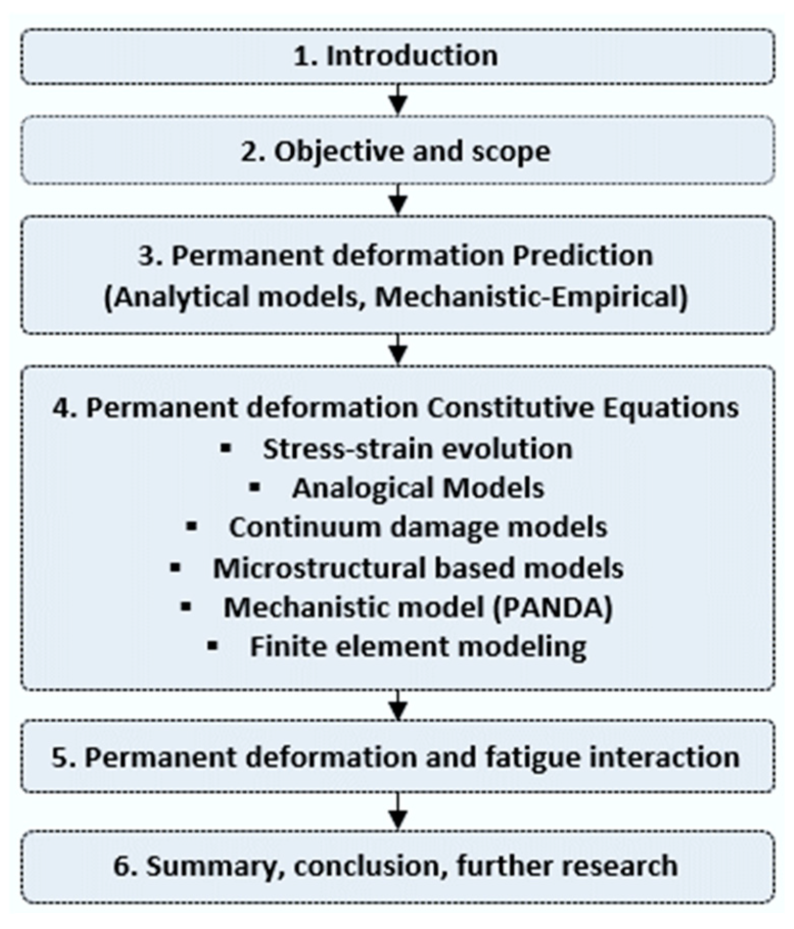
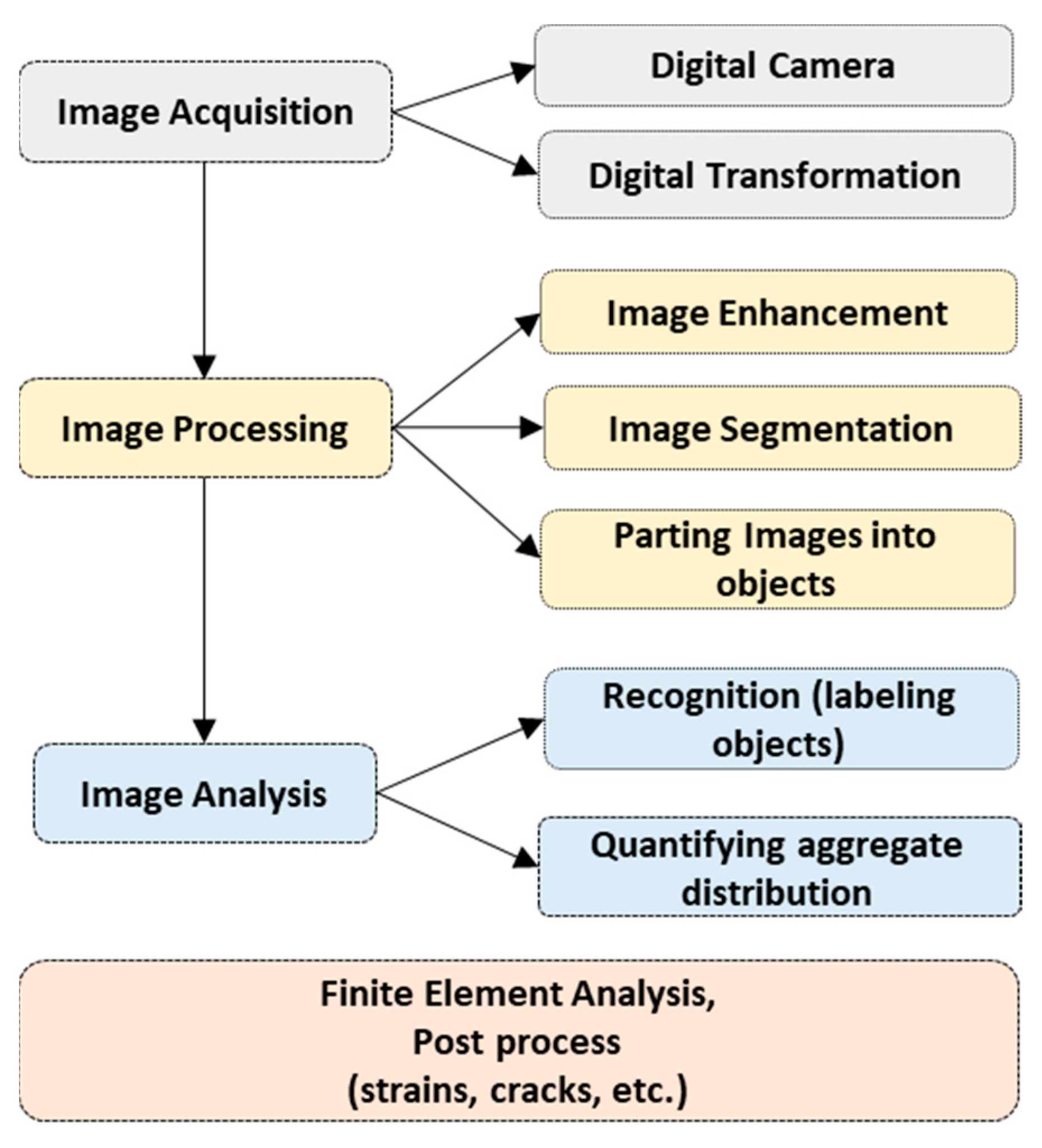
:1. Introduction
2. Objective and Scope
3. Permanent Deformation Prediction
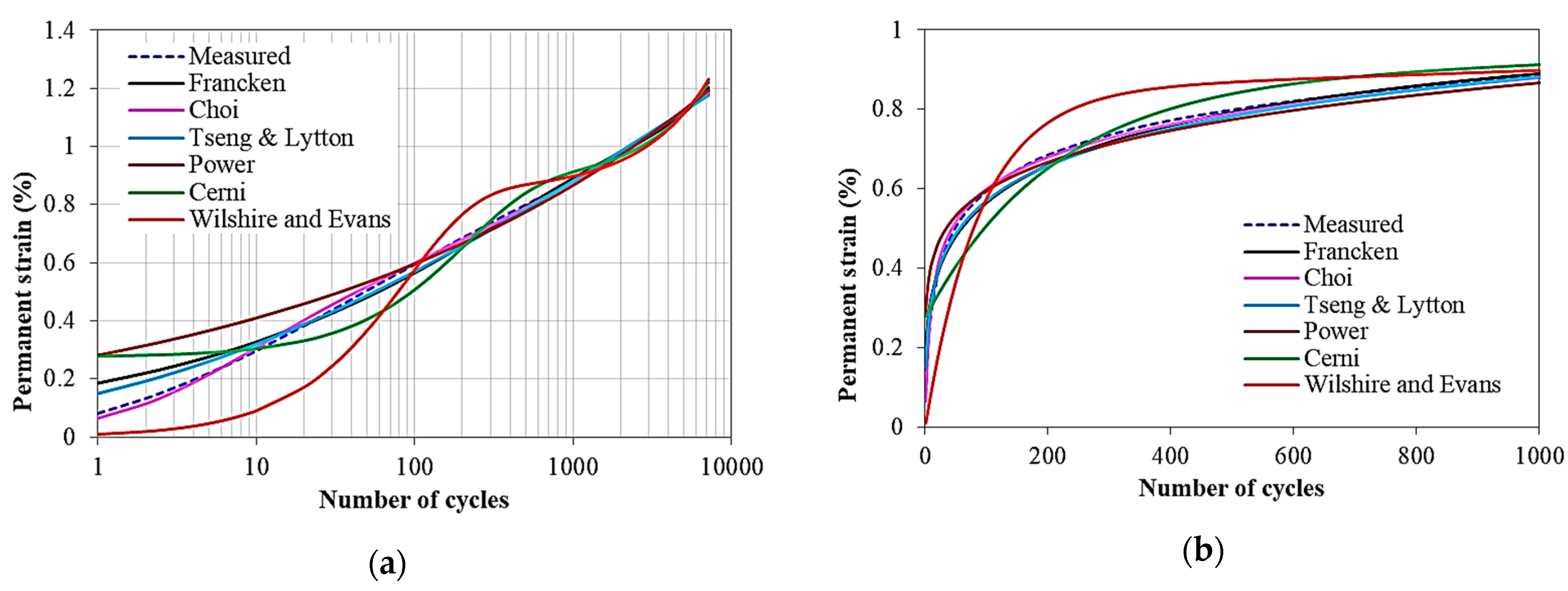
3.1. Analytical Models
3.2. Calibration Tests

| Model (Equation) | Variables | Description | Reference | Calibration Test |
|---|---|---|---|---|
| a, b | Accurate for secondary stages, small stress/strain deformation | Creep, creep-recovery | ||
Where, | A, B, C, D | Most widely used analytical model for permanent deformation in all three creep stages; the first part is a power function (for low stresses). and the second part is for high stresses (tertiary stage). (—maximum stress, – plastic failure threshold; , —axial and lateral stress, —stiffness) | Francken [40] | Repeated triaxial compression |
| , | , S, m | Analytical Power Model based on dissipated energy rate; is a function of resilient modulus and applied stress | Khedr Safwan [41] | Multiple step dynamic test |
| , β, | Widely used analytical model to fit all creep stages | Tseng and Lytton [42] | Triaxial creep-recovery test | |
| ,
, , | Analytical model for three creep stages, mainly developed for unbound materials (, —scale primary and tertiary strain; δ2, —rate parameters) | Wilshire and Evans [43] | Creep tests | |
| , , | Mechanistic-empirical (MEPDG) Model —resilient strain, T—temperature | Triaxial creep-recovery test | ||
| ; ; | a, b, c, d, k | Three-stage rutting model (Modified Francken model) for accurate flow number identification | Zhou et al. [28] | Triaxial creep-recovery test |
| A, B, C, D | Two phase, Linear exponent model (mainly for unbound granular materials) | Cerni et al. [44] | Triaxial creep-recovery test | |
| A, B, C, α | Incremental model: mechanistic based as a function of viscoplastic hardening (H and α), loading time, deviatoric stress, and rest period (A, C contain the parameters related to initial behavior of permanent deformation) | Choi et al. [45] | Triaxial creep-recovery | |
| , , , , , , A, B, C, | A mechanistic shift model based on the load time and stress–shift function (master curve). is atmospheric pressure, is reduced loading time, and is deviatoric stress | Choi et al. [46] | Triaxial creep-recovery | |
| a, b, c | A three-stage model modified from Francken model | Fang et al. [4] | Wheel tracking, Uniaxial cyclic compression |
4. Permanent Deformation Damage Modeling
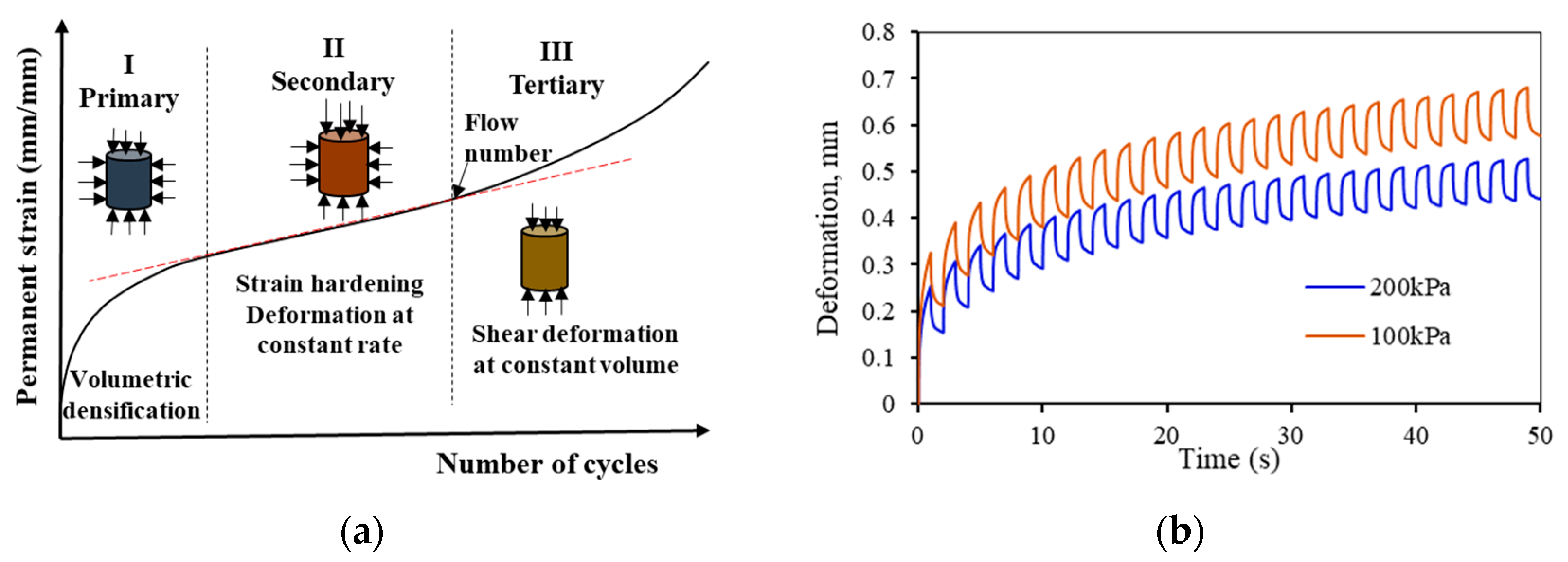
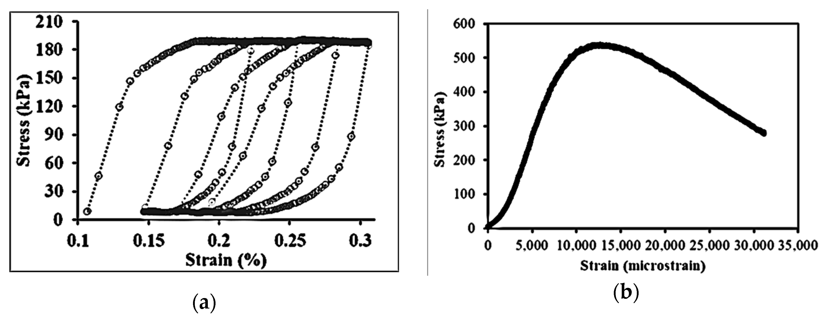
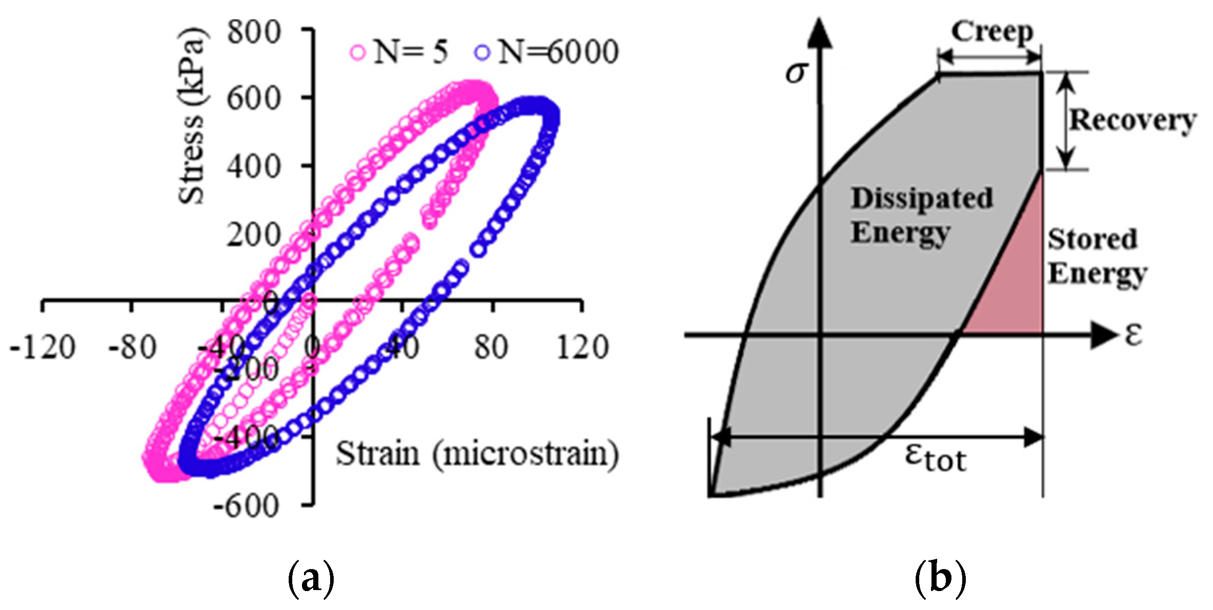
4.1. Stress–Strain Response
4.2. Constitutive Models
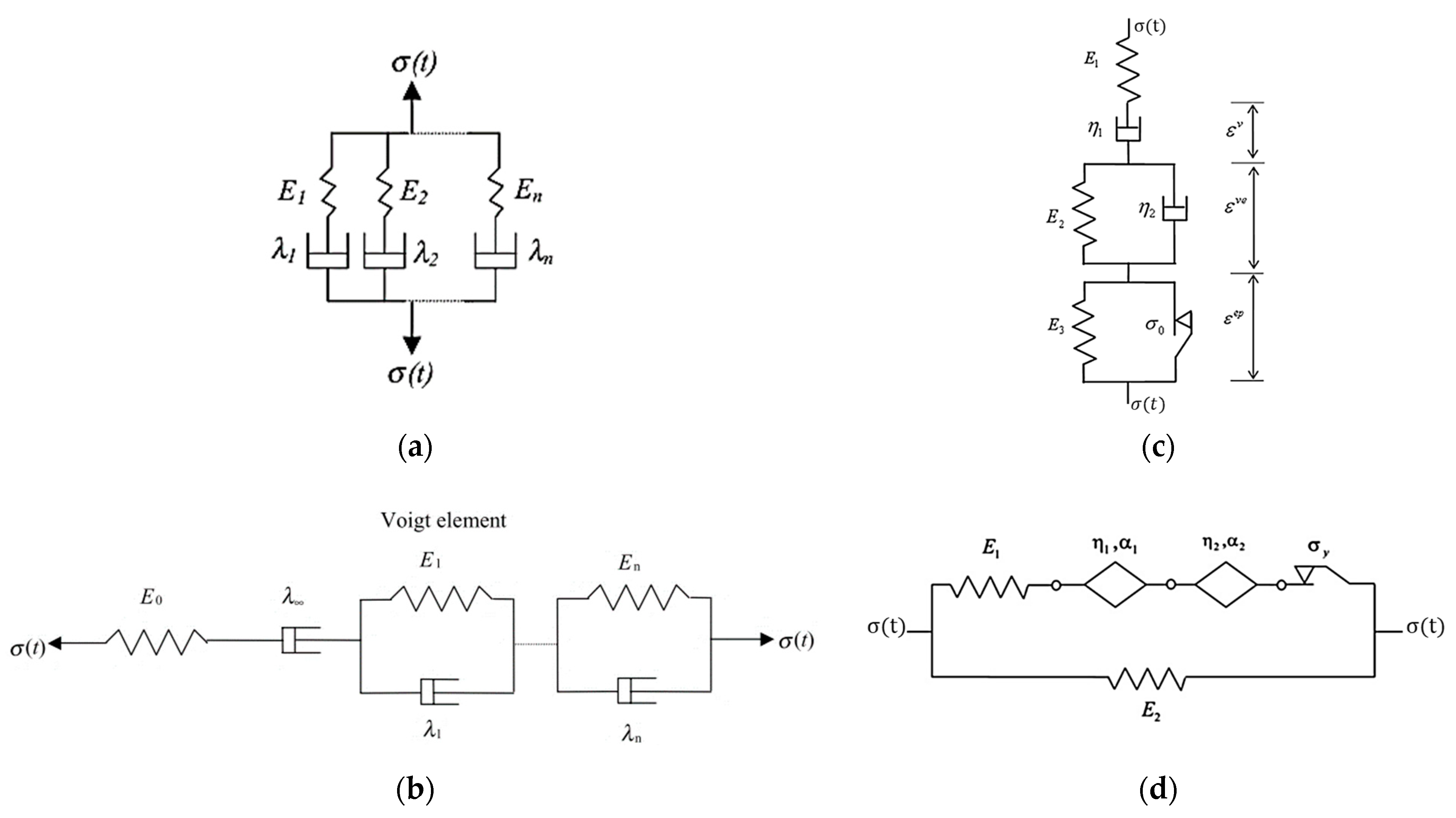
Analogical Models
4.3. Continuum Based Models
4.3.1. Damage Density
4.3.2. Viscoplasticity
4.4. Mechanistic Methods
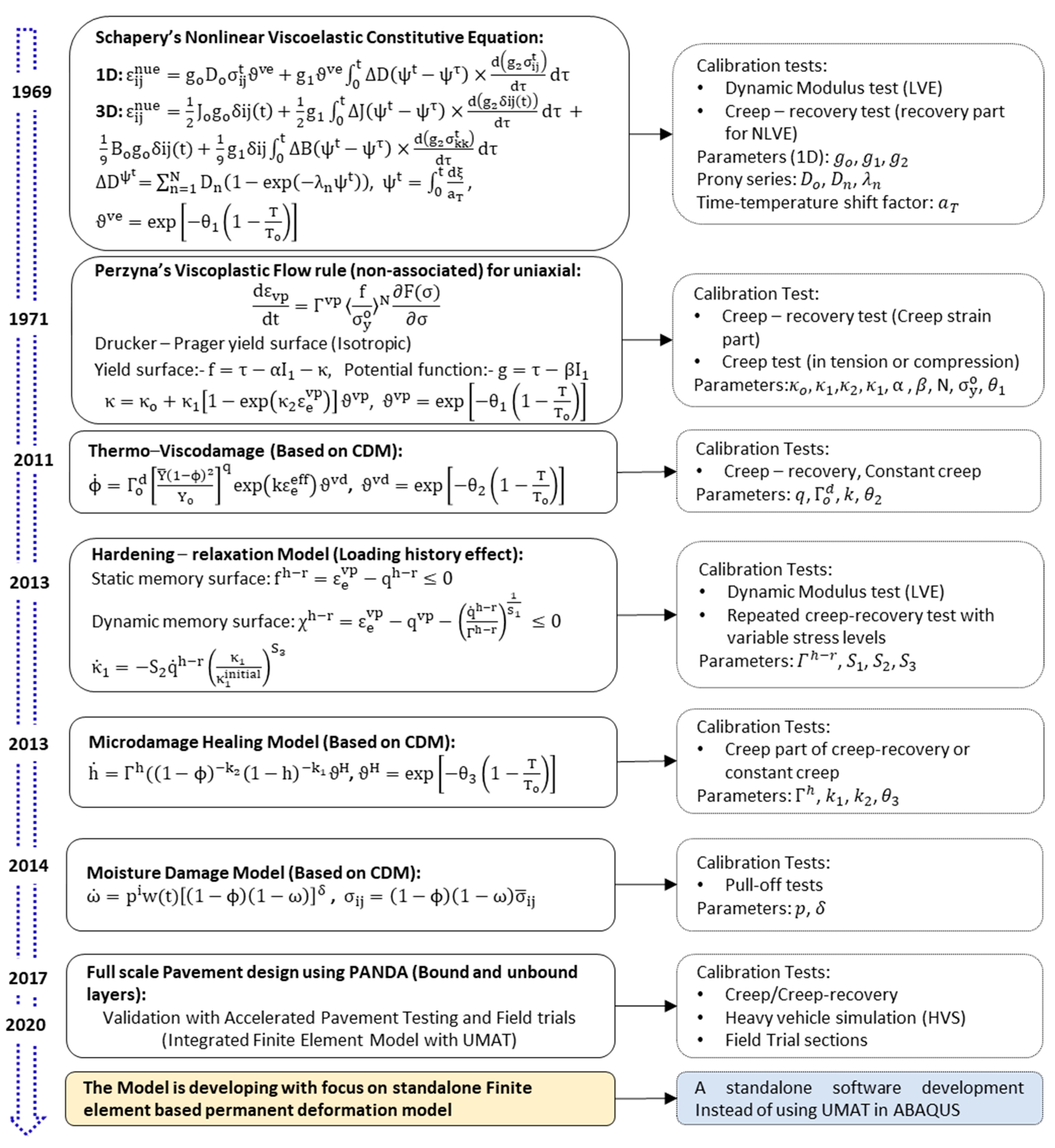
4.4.1. Pavement Analysis Using the Nonlinear Damage Approach (PANDA)
- (1)
- First, the linear and nonlinear viscoelastic variables are obtained from dynamic modulus (for linear viscoelastic) and creep-recovery tests (nonlinear viscoelastic). The nonlinear viscoelastic strain is formulated using the well-known Schapery’s viscoelastic constitutive equation [68].
- (2)
- Secondly, the viscoelastic strain is deducted from the total strain to extract the viscoplastic strain from the same creep-recovery test data using the strain decomposition principle. Then, the classic Perzyna’s viscoplasticity [66] theory is adopted to predict the viscoplastic strain evolution. The Drucker–Prager yield surface function is often used [23,74].
- (3)
- The third foundation of the PANDA constitutive model is the viscodamage model [64] using the continuum damage mechanics (CDM) theory. The effective strain is used in effective configuration. The viscodamage model mainly predicts the permanent deformation in the tertiary creep.
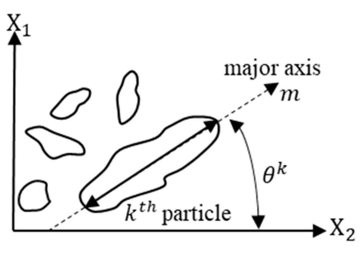
4.4.2. Microstructural Based Models
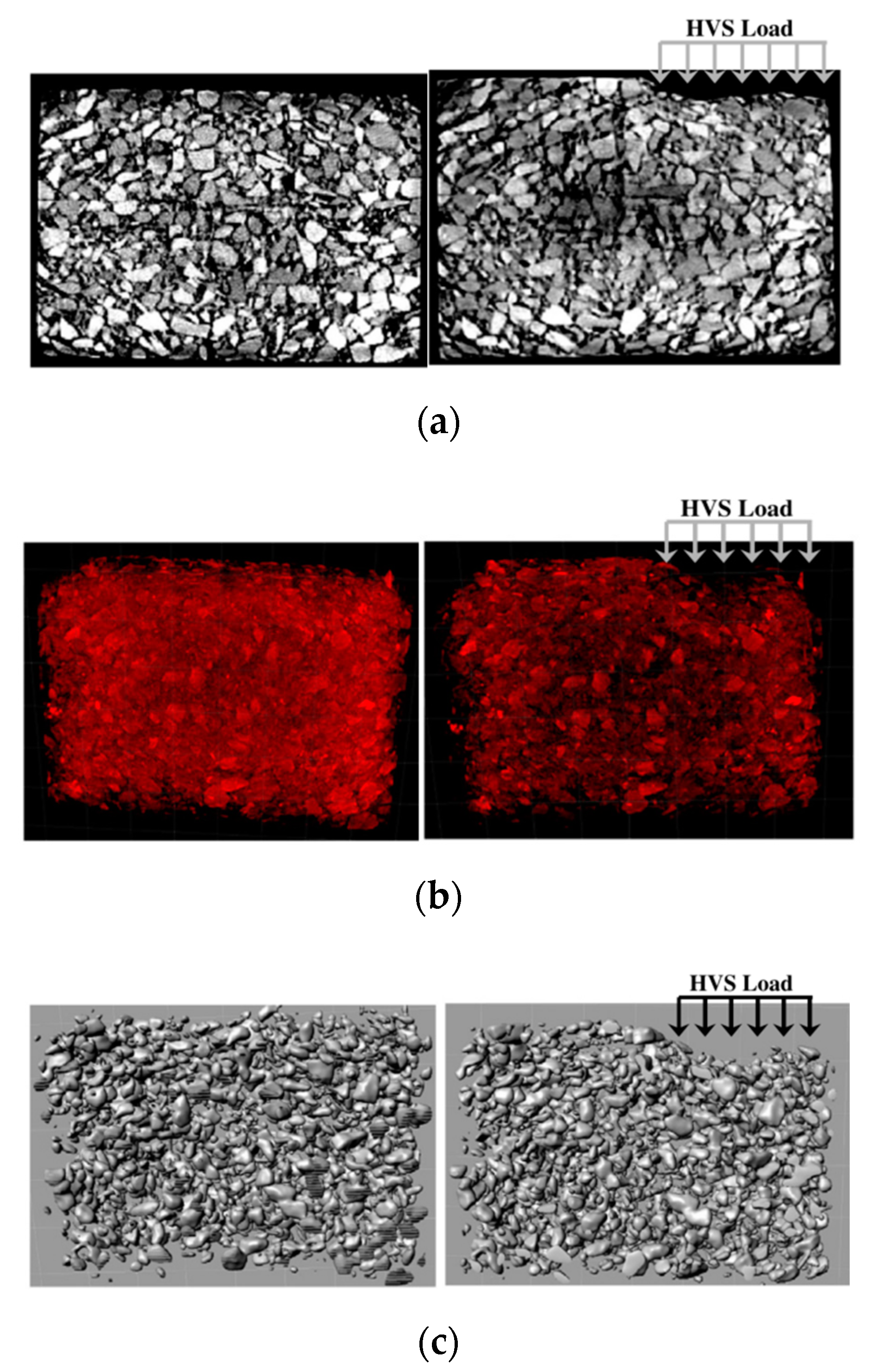
4.4.3. Finite Element Simulation
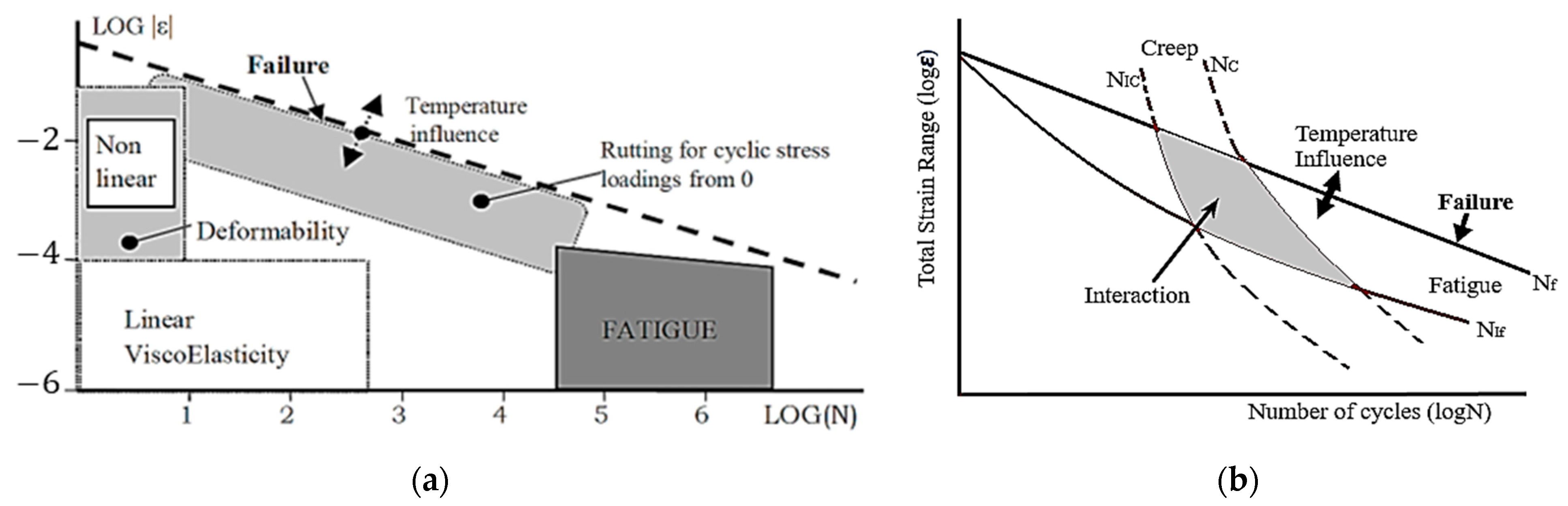
5. Permanent Deformation and Fatigue Interaction Damage
6. Summary, Conclusions, Further Research
6.1. Summary
6.2. Conclusions
6.3. Further Research
Author Contributions
Funding
Institutional Review Board Statement
Informed Consent Statement
Data Availability Statement
Conflicts of Interest
References
- Roberts, F.L.; Mohammad, L.N.; Wang, L.B. History of Hot Mix Asphalt Mixture Design in the United States. J. Mater. Civ. Eng. 2002, 14, 279–293. [Google Scholar] [CrossRef]
- Vesic, A.S.; Domaschuk, L. Theoretical Analysis of Structural Behavior of Road Test Flexible Pavements; National Academy of Science: Washington, DC, USA, 1964. [Google Scholar]
- Archilla, A.R.; Madanat, S. Development of a Pavement Rutting Model from Experimental Data. J. Transp. Eng. 2000, 126, 291–299. [Google Scholar] [CrossRef]
- Fang, H.; Liu, Q.; Mo, L.; Javilla, B.; Shu, B.; Wu, S. Characterization of three-stage rutting development of asphalt mixtures. Constr. Build. Mater. 2017, 154, 340–348. [Google Scholar] [CrossRef]
- Celauro, C. Influence of the Hourly Variation of Temperature on the Estimation of Fatigue Damage and Rutting in Flexible Pavement Design. Int. J. Pavement Eng. 2004, 5, 221–231. [Google Scholar] [CrossRef]
- Delgadillo, R.; Bahia, H.U. The Relationship between Nonlinearity of Asphalt Binders and Asphalt Mixture Permanent Deformation. Road Mater. Pavement Des. 2010, 11, 653–680. [Google Scholar] [CrossRef]
- Kennedy, T.W.; Huber, G.A.; Harrigan, E.T.; Cominsky, R.J.; Hughes, C.S.; Von Quintus, H.; Moulthrop, J.S. Superior Performing Asphalt Pavements (Superpave): The Product of the SHRP Asphalt Research Program; Strategic Highway Research Program, National Research Council: Washington, DC, USA, 1994. [Google Scholar]
- Laukkanen, O.-V.; Soenen, H.; Pellinen, T.; Heyrman, S.; Lemoine, G. Creep-recovery behavior of bituminous binders and its relation to asphalt mixture rutting. Mater. Struct. 2014, 48, 4039–4053. [Google Scholar] [CrossRef]
- Meena, S.; Biligiri, K.P. Binder rheological predictive models to evaluate rutting performance of asphalt mixtures. Constr. Build. Mater. 2016, 111, 556–564. [Google Scholar] [CrossRef]
- İskender, E. Rutting evaluation of stone mastic asphalt for basalt and basalt–limestone aggregate combinations. Compos. Part B Eng. 2013, 54, 255–264. [Google Scholar] [CrossRef]
- Masad, E.; Olcott, D.; White, T.; Tashman, L. Correlation of Fine Aggregate Imaging Shape Indices with Asphalt Mixture Performance. Transp. Res. Rec. J. Transp. Res. Board 2001, 1757, 148–156. [Google Scholar] [CrossRef]
- Kandhal, P.S.; Cooley, L. Coarse- Versus Fine-Graded Superpave Mixtures: Comparative Evaluation of Resistance to Rutting. Transp. Res. Rec. J. Transp. Res. Board 2002, 1789, 216–224. [Google Scholar] [CrossRef] [Green Version]
- Singh, M.; Kumar, P.; Anupam, A.K. Effect of type of aggregate on permanent deformation of bituminous concrete mixes. Road Mater. Pavement Des. 2016, 17, 417–433. [Google Scholar] [CrossRef]
- Lundberg, J.; Janhäll, S.; Gustafsson, M.; Erlingsson, S. Calibration of the Swedish studded tyre abrasion wear prediction model with implication for the NORTRIP road dust emission model. Int. J. Pavement Eng. 2019, 22, 432–446. [Google Scholar] [CrossRef] [Green Version]
- Ahmed, A.; Erlingsson, S. Evaluation of permanent deformation models for unbound granular materials using accelerated pavement tests. Road Mater. Pavement Des. 2013, 14, 178–195. [Google Scholar] [CrossRef]
- Deacon, J.A.; Harvey, J.T.; Guada, I.; Popescu, L.; Monismith, C.L. Analytically Based Approach to Rutting Prediction. Transp. Res. Rec. J. Transp. Res. Board 2002, 1806, 9–18. [Google Scholar] [CrossRef]
- Song, J.; Pellinen, T. Dilation Behavior of Hot Mix Asphalt Under Triaxial Loading. Road Mater. Pavement Des. 2007, 8, 103–125. [Google Scholar] [CrossRef]
- Park, S.W.; Richard Kim, Y.; Schapery, R.A. A viscoelastic continuum damage model and its application to uniaxial behavior of asphalt concrete. Mech. Mater. 1996, 24, 241–255. [Google Scholar] [CrossRef]
- Tashman, L.; Masad, E.; Zbib, H.; Little, D.; Kaloush, K. Microstructural Viscoplastic Continuum Model for Permanent Deformation in Asphalt Pavements. J. Eng. Mech. 2005, 131, 48–57. [Google Scholar] [CrossRef]
- Yu, H.; Muhunthan, B.; Shen, S. Anisotropic Nonlinear Elastoviscoplastic Model for Rutting of Asphalt Mixtures. J. Eng. Mech. 2014, 140, 242–249. [Google Scholar] [CrossRef]
- Kim, Y.-R.; Lutif, J.E.S.; Allen, D.H. Determining Representative Volume Elements of Asphalt Concrete Mixtures without Damage. Transp. Res. Rec. J. Transp. Res. Board 2009, 2127, 52–59. [Google Scholar] [CrossRef]
- Underwood, S.; Heidari, A.H.; Guddati, M.; Kim, Y.R. Experimental Investigation of Anisotropy in Asphalt Concrete. Transp. Res. Rec. J. Transp. Res. Board 2005, 1929, 238–247. [Google Scholar] [CrossRef]
- Darabi, M.K.; Abu Al-Rub, R.K.; Masad, E.A.; Huang, C.-W.; Little, D.N. A modified viscoplastic model to predict the permanent deformation of asphaltic materials under cyclic-compression loading at high temperatures. Int. J. Plast. 2012, 35, 100–134. [Google Scholar] [CrossRef]
- Darabi, M.K.; Abu Al-Rub, R.K.; Masad, E.A.; Little, D.N. Cyclic Hardening-Relaxation Viscoplasticity Model for Asphalt Concrete Materials. J. Eng. Mech. 2013, 139, 832–847. [Google Scholar] [CrossRef]
- Karimi, M.M.; Tabatabaee, N.; Jahangiri, B.; Darabi, M.K. Constitutive modeling of hardening-relaxation response of asphalt concrete in cyclic compressive loading. Constr. Build. Mater. 2017, 137, 169–184. [Google Scholar] [CrossRef]
- Blanc, J.; Gabet, T.; Hornych, P.; Piau, J.-M.; Di Benedetto, H. Cyclic triaxial tests on bituminous mixtures. Road Mater. Pavement Des. 2014, 16, 46–69. [Google Scholar] [CrossRef] [Green Version]
- Airey, G.D.; Rahimzadeh, B.; Collop, A.C. Viscoelastic linearity limits for bituminous materials. Mater. Struct. 2003, 36, 643–647. [Google Scholar] [CrossRef]
- Zhou, F.; Scullion, T.; Sun, L. Verification and Modeling of Three-Stage Permanent Deformation Behavior of Asphalt Mixes. J. Transp. Eng. 2004, 130, 486–494. [Google Scholar] [CrossRef]
- Zhou, F.; Scullion, T. Discussion: Three Stages of Permanent Deformation Curve and Rutting Model. Int. J. Pavement Eng. 2002, 3, 251–260. [Google Scholar] [CrossRef]
- Biligiri, K.P.; Kaloush, K.E.; Mamlouk, M.S.; Witczak, M.W. Rational Modeling of Tertiary Flow for Asphalt Mixtures. Transp. Res. Rec. J. Transp. Res. Board 2007, 2001, 63–72. [Google Scholar] [CrossRef]
- Ameri, M.; Sheikhmotevali, A.H.; Fasihpour, A. Evaluation and comparison of flow number calculation methods. Road Mater. Pavement Des. 2014, 15, 182–206. [Google Scholar] [CrossRef]
- Javilla, B.; Mo, L.; Hao, F.; An, S.; Wu, S. Systematic comparison of two-stage analytical rutting models of asphalt mixtures. Constr. Build. Mater. 2017, 153, 716–727. [Google Scholar] [CrossRef]
- Sousa, J.B.; Craus, J.; Monismith, C.L. Summary Report on Permanent Deformation in Asphalt Concrete; University of California: Berkeley, CA, USA, 1991. [Google Scholar]
- Uzan, J.; Motola, Y. Damage Evaluation in Simple Shear Tests with and without Stress Reversal of Asphalt Concrete. Road Mater. Pavement Des. 2006, 7, 71–86. [Google Scholar] [CrossRef]
- Li, Q.; Lee, H.J.; Lee, S.Y. Permanent Deformation Model Based on Shear Properties of Asphalt Mixtures: Development and Calibration. Transp. Res. Rec. 2011, 2210, 81–89. [Google Scholar] [CrossRef]
- Zieliński, P. Indirect tensile test as a simple method for rut resistance evaluation of asphalt mixtures—Polish experience. Road Mater. Pavement Des. 2020, 23, 112–128. [Google Scholar] [CrossRef]
- Perraton, D.; Di Benedetto, H.; Sauzéat, C.; De La Roche, C.; Bankowski, W.; Partl, M.; Grenfell, J. Rutting of bituminous mixtures: Wheel tracking tests campaign analysis. Mater. Struct. 2011, 44, 969–986. [Google Scholar] [CrossRef]
- Mohammad, L.N.; Elseifi, M.; Cao, W.; Raghavendra, A.; Ye, M. Evaluation of various Hamburg wheel-tracking devices and AASHTO T 324 specification for rutting testing of asphalt mixtures. Road Mater. Pavement Des. 2017, 18, 128–143. [Google Scholar] [CrossRef]
- Ahmed, A.W.; Erlingsson, S. Evaluation of a permanent deformation model for asphalt concrete mixtures using extra-large wheel-tracking and heavy vehicle simulator tests. Road Mater. Pavement Des. 2014, 16, 154–171. [Google Scholar] [CrossRef]
- Francken, L. Permanent deformation law of bituminous road mixes in repeated triaxial compression. In Proceedings of the 4th International Conference on Structural Design of Asphalt Pavements, Ann Arbor, MI, USA, 22–26 August 1977; pp. 483–496. [Google Scholar]
- Khedr Safwan, A. Deformation Mechanism in Asphaltic Concrete. J. Transp. Eng. 1986, 112, 29–45. [Google Scholar] [CrossRef]
- Tseng, K.-H.; Lytton, R.L. Prediction of Permanent Deformation in Flexible Pavement Materials. In Implication of Aggregates in the Design, Construction and Performance of Flexible Pavements; ASTM International: West Conshohocken, PA, USA, 1989; Volume 1016, pp. 154–172. [Google Scholar]
- Wilshire, B.; Evans, R.W. Acquisition and analysis of creep data. J. Strain Anal. Eng. Des. 1994, 29, 159–165. [Google Scholar] [CrossRef]
- Cerni, G.; Cardone, F.; Virgili, A.; Camilli, S. Characterisation of permanent deformation behaviour of unbound granular materials under repeated triaxial loading. Constr. Build. Mater. 2012, 28, 79–87. [Google Scholar] [CrossRef]
- Choi, Y.T.; Subramanian, V.; Guddati, M.N.; Kim, Y.R. Incremental Model for Prediction of Permanent Deformation of Asphalt Concrete in Compression. Transp. Res. Rec. 2012, 2296, 24–35. [Google Scholar] [CrossRef]
- Choi, Y.-T.; Kim, Y.R. Development of characterisation models for incremental permanent deformation model for asphalt concrete in confined compression. Road Mater. Pavement Des. 2013, 14, 266–288. [Google Scholar] [CrossRef]
- Yun, T.; Kim, Y.R. A viscoplastic constitutive model for hot mix asphalt in compression at high confining pressure. Constr. Build. Mater. 2011, 25, 2733–2740. [Google Scholar] [CrossRef]
- Subramanian, V.; Guddati, M.N.; Richard Kim, Y. A viscoplastic model for rate-dependent hardening for asphalt concrete in compression. Mech. Mater. 2013, 59, 142–159. [Google Scholar] [CrossRef] [Green Version]
- Levenberg, E.; Uzan, J. Triaxial Small-Strain Viscoelastic-Viscoplastic Modeling of Asphalt Aggregate Mixes. Mech. Time-Depend. Mater. 2004, 8, 365–384. [Google Scholar] [CrossRef]
- Di Benedetto, H.; Nguyen, Q.T.; Sauzéat, C. Nonlinearity, Heating, Fatigue and Thixotropy during Cyclic Loading of Asphalt Mixtures. Road Mater. Pavement Des. 2011, 12, 129–158. [Google Scholar] [CrossRef]
- Perl, M.; Uzan, J.; Sides, A. Visco-elasto-plastic constitutive law for a bituminous mixture under repeated loading. Transp. Res. Rec. 1983, 911, 20–26. [Google Scholar]
- Sides, A.; Uzan, J.; Perl, M. A comprehensive viscoelasto-plastic characterization of sand-asphalt compressive and tensile cyclic loading. J. Test. Eval. 1985, 13, 49–59. [Google Scholar]
- Cao, W.; Kim, Y.R. A viscoplastic model for the confined permanent deformation of asphalt concrete in compression. Mech. Mater. 2016, 92, 235–247. [Google Scholar] [CrossRef]
- Uzan, J. Permanent Deformation in Flexible Pavements. J. Transp. Eng. 2004, 130, 6–13. [Google Scholar] [CrossRef]
- Park, S.; Kim, Y. Interconversion between relaxation modulus and creep compliance for viscoelastic solids. J. Mater. Civ. Eng. 1999, 11, 76–82. [Google Scholar] [CrossRef]
- Mun, S.; Chehab, G.R.; Kim, Y.R. Determination of Time-domain Viscoelastic Functions using Optimized Interconversion Techniques. Road Mater. Pavement Des. 2007, 8, 351–365. [Google Scholar] [CrossRef]
- Collop, A.C.; Scarpas, A.; Kasbergen, C.; De Bondt, A. Development and Finite Element Implementation of Stress-Dependent Elastoviscoplastic Constitutive Model with Damage for Asphalt. Transp. Res. Rec. J. Transp. Res. Board 2003, 1832, 96–104. [Google Scholar] [CrossRef]
- Di Benedetto, H.; Mondher, N.; Sauzéat, C.; Olard, F. Three-dimensional Thermo-viscoplastic Behaviour of Bituminous Materials: The DBN Model. Road Mater. Pavement Des. 2007, 8, 285–315. [Google Scholar] [CrossRef]
- Olard, F.; Di Benedetto, H. General “2S2P1D” Model and Relation Between the Linear Viscoelastic Behaviours of Bituminous Binders and Mixes. Road Mater. Pavement Des. 2003, 4, 185–224. [Google Scholar] [CrossRef]
- Grzesikiewicz, W.; Wakulicz, A.; Zbiciak, A. Non-linear problems of fractional calculus in modeling of mechanical systems. Int. J. Mech. Sci. 2013, 70, 90–98. [Google Scholar] [CrossRef]
- Zbiciak, A. Mathematical description of rheological properties of asphalt-aggregate mixes. Bull. Pol. Acad. Sci. Tech. Sci. 2013, 61, 65–72. [Google Scholar] [CrossRef] [Green Version]
- Di Benedetto, H.; Olard, F.; Sauzéat, C.; Delaporte, B. Linear viscoelastic behaviour of bituminous materials: From binders to mixes. Road Mater. Pavement Des. 2004, 5, 163–202. [Google Scholar] [CrossRef]
- Kachanov, L.M. On time to rupture in creep conditions. Izv. Akad. Nauk SSSR 1958, 8, 26–31. (In Russian) [Google Scholar]
- Darabi, M.K.; Abu Al-Rub, R.K.; Masad, E.A.; Huang, C.-W.; Little, D.N. A thermo-viscoelastic–viscoplastic–viscodamage constitutive model for asphaltic materials. Int. J. Solids Struct. 2011, 48, 191–207. [Google Scholar] [CrossRef] [Green Version]
- Rabotnov, I.N.; Rabotnov, I.U.N.; Rabotnov, I.U.r.N.; Rabotnov, J.N.; Rabotnov, Y.N.; Leckie, F.A. Creep Problems in Structural Members; North-Holland Publishing Company: Amsterdam, The Netherlands, 1969; Volume 7. [Google Scholar]
- Perzyna, P. Thermodynamic Theory of Viscoplasticity. In Advances in Applied Mechanics; Elsevier: Amsterdam, The Netherlands, 1971; pp. 313–354. [Google Scholar]
- Rushing, J.F.; Darabi, M.K.; Rahmani, E.; Little, D.N. Comparing rutting of airfield pavements to simulations using Pavement Analysis Using Nonlinear Damage Approach (PANDA). Int. J. Pavement Eng. 2017, 18, 138–159. [Google Scholar] [CrossRef]
- Schapery, R.A. On the characterization of nonlinear viscoelastic materials. Polym. Eng. Sci. 1969, 9, 295–310. [Google Scholar] [CrossRef]
- Huang, C.-W.; Abu Al-Rub, R.K.; Masad, E.A.; Little, D.N.; Airey, G.D. Numerical implementation and validation of a nonlinear viscoelastic and viscoplastic model for asphalt mixes. Int. J. Pavement Eng. 2011, 12, 433–447. [Google Scholar] [CrossRef]
- Abu Al-Rub, R.K.; Darabi, M.K.; Kim, S.-M.; Little, D.N.; Glover, C.J. Mechanistic-based constitutive modeling of oxidative aging in aging-susceptible materials and its effect on the damage potential of asphalt concrete. Constr. Build. Mater. 2013, 41, 439–454. [Google Scholar] [CrossRef]
- Abu Al-Rub, R.K.; Darabi, M.K.; Little, D.N.; Masad, E.A. A micro-damage healing model that improves prediction of fatigue life in asphalt mixes. Int. J. Eng. Sci. 2010, 48, 966–990. [Google Scholar] [CrossRef]
- Shakiba, M.; Darabi, M.K.; Abu Al-Rub, R.K.; You, T.; Little, D.N.; Masad, E.A. Three-dimensional microstructural modelling of coupled moisture–mechanical response of asphalt concrete. Int. J. Pavement Eng. 2015, 16, 445–466. [Google Scholar] [CrossRef]
- Huang, C.-W.; Abu Al-Rub, R.K.; Masad, E.A.; Little, D.N. Three-Dimensional Simulations of Asphalt Pavement Permanent Deformation Using a Nonlinear Viscoelastic and Viscoplastic Model. J. Mater. Civ. Eng. 2011, 23, 56–68. [Google Scholar] [CrossRef] [Green Version]
- Darabi, M.K.; Kola, R.; Little, D.N.; Garg, N. Time-dependent Drucker-Prager-Cap model coupled with PANDA (Pavement Analysis Using Nonlinear Damage Approach) to predict rutting performance of flexible pavements. Constr. Build. Mater. 2020, 244, 118326. [Google Scholar] [CrossRef]
- Rahmani, E.; Darabi, M.K.; Abu Al-Rub, R.K.; Kassem, E.; Masad, E.A.; Little, D.N. Effect of confinement pressure on the nonlinear-viscoelastic response of asphalt concrete at high temperatures. Constr. Build. Mater. 2013, 47, 779–788. [Google Scholar] [CrossRef]
- Darabi, M.K.; Kola, R.; Little, D.N.; Rahmani, E.; Garg, N. Predicting Rutting Performance of Flexible Airfield Pavements Using a Coupled Viscoelastic-Viscoplastic-Cap Constitutive Relationship. J. Eng. Mech. 2019, 145, 04018129. [Google Scholar] [CrossRef]
- Behnke, R.; Wollny, I.; Hartung, F.; Kaliske, M. Thermo-mechanical finite element prediction of the structural long-term response of asphalt pavements subjected to periodic traffic load: Tire-pavement interaction and rutting. Comput. Struct. 2019, 218, 9–31. [Google Scholar] [CrossRef]
- Kim, S.-M.; Darabi, M.K.; Little, D.N.; Abu Al-Rub, R.K. Effect of the Realistic Tire Contact Pressure on the Rutting Performance of Asphaltic Concrete Pavements. KSCE J. Civ. Eng. 2018, 22, 2138–2146. [Google Scholar] [CrossRef]
- You, T.; Im, S.; Kim, Y.-R.; Little, D.N. Mechanistic Modeling to Evaluate Structural Performance of Bituminous Pavements with Inelastic Deformation and Fatigue Damage of Mixtures. J. Eng. Mech. 2017, 143, 04016126. [Google Scholar] [CrossRef]
- Abu Al-Rub, R.K.; Darabi, M.K.; Huang, C.-W.; Masad, E.A.; Little, D.N. Comparing finite element and constitutive modelling techniques for predicting rutting of asphalt pavements. Int. J. Pavement Eng. 2012, 13, 322–338. [Google Scholar] [CrossRef]
- Mulugeta Alamnie, M.; Taddesse, E.; Hoff, I. Thermo-piezo-rheological characterization of asphalt concrete. Constr. Build. Mater. 2022, 329, 127106. [Google Scholar] [CrossRef]
- Lai, J.; Bakker, A. 3-D Schapery representation for non-linear viscoelasticity and finite element implementation. Comput. Mech. 1996, 18, 182–191. [Google Scholar] [CrossRef]
- Darabi, M.K.; Abu Al-Rub, R.K.; Masad, E.A.; Little, D.N. Constitutive modeling of fatigue damage response of asphalt concrete materials with consideration of micro-damage healing. Int. J. Solids Struct. 2013, 50, 2901–2913. [Google Scholar] [CrossRef] [Green Version]
- Shakiba, M.; Darabi, M.K.; Abu Al-Rub, R.K.; Masad, E.A.; Little, D.N. Microstructural modeling of asphalt concrete using a coupled moisture–mechanical constitutive relationship. Int. J. Solids Struct. 2014, 51, 4260–4279. [Google Scholar] [CrossRef] [Green Version]
- Yideti, T.F.; Birgisson, B.; Jelagin, D.; Guarin, A. Packing theory-based framework to evaluate permanent deformation of unbound granular materials. Int. J. Pavement Eng. 2013, 14, 309–320. [Google Scholar] [CrossRef]
- Oda, M.; Nakayama, H. Yield Function for Soil with Anisotropic Fabric. J. Eng. Mech. 1989, 115, 89–104. [Google Scholar] [CrossRef]
- Tashman, L.; Masad, E.; Little, D.; Zbib, H. A microstructure-based viscoplastic model for asphalt concrete. Int. J. Plast. 2005, 21, 1659–1685. [Google Scholar] [CrossRef]
- Coleri, E.; Harvey, J.T.; Yang, K.; Boone, J.M. A micromechanical approach to investigate asphalt concrete rutting mechanisms. Constr. Build. Mater. 2012, 30, 36–49. [Google Scholar] [CrossRef]
- Chehab, G.R.; Seo, Y.; Kim, Y.R. Viscoelastoplastic damage characterization of asphalt-aggregate mixtures using digital image correlation. Int. J. Geomech. 2007, 7, 111–118. [Google Scholar] [CrossRef]
- Shojaeifard, M.; Baghani, M.; Shahsavari, H. Rutting investigation of asphalt pavement subjected to moving cyclic loads: An implicit viscoelastic–viscoplastic–viscodamage FE framework. Int. J. Pavement Eng. 2018, 21, 1393–1407. [Google Scholar] [CrossRef]
- Underwood, B.S. A continuum damage model for asphalt cement and asphalt mastic fatigue. Int. J. Fatigue 2016, 82, 387–401. [Google Scholar] [CrossRef]
- Pellinen, T.K.; Christensen, D.W.; Rowe, G.M.; Sharrock, M. Fatigue-Transfer Functions: How Do They Compare? Transp. Res. Rec. J. Transp. Res. Board 2004, 1896, 77–87. [Google Scholar] [CrossRef]
- Ling, M.; Luo, X.; Chen, Y.; Gu, F.; Lytton, R.L. Mechanistic-empirical models for top-down cracking initiation of asphalt pavements. Int. J. Pavement Eng. 2018, 21, 464–473. [Google Scholar] [CrossRef]
- Zhang, Y.; Luo, X.; Luo, R.; Lytton, R.L. Crack initiation in asphalt mixtures under external compressive loads. Constr. Build. Mater. 2014, 72, 94–103. [Google Scholar] [CrossRef] [Green Version]
- Dyskin, A.V.; Sahouryeh, E.; Jewell, R.J.; Joer, H.; Ustinov, K.B. Influence of shape and locations of initial 3-D cracks on their growth in uniaxial compression. Eng. Fract. Mech. 2003, 70, 2115–2136. [Google Scholar] [CrossRef]
- Onifade, I.; Birgisson, B.; Balieu, R. Energy-based damage and fracture framework for viscoelastic asphalt concrete. Eng. Fract. Mech. 2015, 145, 67–85. [Google Scholar] [CrossRef]
- Widyatmoko, I.; Ellis, C.; Read, J.M. Energy dissipation and the deformation resistance of bituminous mixtures. Mater. Struct. 1999, 32, 218–223. [Google Scholar] [CrossRef]
- Ghuzlan, K.A.; Carpenter, S.H. Energy-Derived, Damage-Based Failure Criterion for Fatigue Testing. Transp. Res. Rec. J. Transp. Res. Board 2000, 1723, 141–149. [Google Scholar] [CrossRef]
- Luo, X.; Luo, R.; Lytton, R.L. Energy-based mechanistic approach for damage characterization of pre-flawed visco-elasto-plastic materials. Mech. Mater. 2014, 70, 18–32. [Google Scholar] [CrossRef]
- Di Benedetto, H.; Partl, M.N.; Francken, L.; De La Roche Saint André, C. Stiffness testing for bituminous mixtures. Mater. Struct. 2001, 34, 66–70. [Google Scholar] [CrossRef]
- Skelton, R.P.; Gandy, D. Creep-fatigue damage accumulation and interaction diagram based on metallographic interpretation of mechanisms. Mater. High Temp. 2008, 25, 27–54. [Google Scholar] [CrossRef]
- Chaboche, J.L. Constitutive equations for cyclic plasticity and cyclic viscoplasticity. Int. J. Plast. 1989, 5, 247–302. [Google Scholar] [CrossRef]
- Barbera, D.; Chen, H.; Liu, Y. On Creep Fatigue Interaction of Components at Elevated Temperature. J. Press. Vessel Technol. 2016, 138, 041403. [Google Scholar] [CrossRef] [Green Version]
- Liu, H.; Yang, X.; Jiang, L.; Lv, S.; Huang, T.; Yang, Y. Fatigue-creep damage interaction model of asphalt mixture under the semi-sine cycle loading. Constr. Build. Mater. 2020, 251, 119070. [Google Scholar] [CrossRef]
- Gupta, R.; Atul Narayan, S.P. Tensile creep of asphalt concrete in repeated loading tests and its effect on energy dissipation. Int. J. Pavement Eng. 2019, 22, 927–939. [Google Scholar] [CrossRef]
- Zhang, Y.; Luo, R.; Lytton, R.L. Characterizing Permanent Deformation and Fracture of Asphalt Mixtures by Using Compressive Dynamic Modulus Tests. J. Mater. Civ. Eng. 2012, 24, 898–906. [Google Scholar] [CrossRef]
- Chaboche, J.L.; Lesne, P.M. A Non-Linear Continuous Fatigue Damage Model. Fatigue Fract. Eng. Mater. Struct. 1988, 11, 1–17. [Google Scholar] [CrossRef]
- Cheng, G. A fatigue damage accumulation model based on continuum damage mechanics and ductility exhaustion. Int. J. Fatigue 1998, 20, 495–501. [Google Scholar] [CrossRef]
- Lemaitre, J.; Plumtree, A. Application of Damage Concepts to Predict Creep-Fatigue Failures. J. Eng. Mater. Technol. 1979, 101, 284–292. [Google Scholar] [CrossRef]


| Parameter | Physical Meaning | Theory/Domain | Calibration Test |
|---|---|---|---|
| Viscoelastic Model Parameters [68,82] | |||
| Instantaneous creep compliance. Characterizes the instantaneous elastic part of the viscoelastic strain | Linear viscoelastic | Creep compliance or Dynamic Modulus | |
| nth retardation time. A measure of the required time for the viscoelastic material to relax the induced stress | |||
| nth coefficient of the Prony series associated with the nth retardation time kn. These parameters characterize the transient compliance of the material | |||
| , , | Nonlinear viscoelastic parameters, where measures the reduction or the increase in the instantaneous compliance; defines the nonlinearity effects in the transient compliance; and is the nonlinear parameter accounting for the loading rate effects on the creep response | Schapery’s Nonlinear viscoelastic | Creep-recovery |
| Viscoplastic Model Parameters [64,66,69] | |||
| Viscoplastic fluidity parameter, such that is a measure of viscoplastic viscosity | Perzyna’s Viscoplastic (with Drucker–Prager yield criteria) | Creep, creep-recovery (creep part), constrain strain rate test | |
| , , | Isotropic hardening parameters, where defines the initial yield strength; defines the saturated limit of the hardening function; and defines the hardening rate and controls the shape of the hardening function versus the effective viscoplastic strain () | ||
| Viscoplastic rate sensitivity exponent and describes the nonlinear rate dependency of viscoplastic response | |||
| , | Govern the pressure sensitivity of the yield surface and plastic potential functions. Related to the angle of friction in the asphalt concrete | ||
| Model parameter distinguishing viscoplastic responses in extension and contraction modes of loading | |||
| Visco-damage Model Parameters [64] | |||
| Visco-damage fluidity parameter ( is a measure of damage viscosity) | CDM (Tertiary creep) | Creep tests | |
| Stress dependency parameter. Defines the sensitivity of the damage evolution due to stress level | |||
| The reference damage force obtained at a reference stress of a creep test | |||
| Strain exponent parameter. Defines the sensitivity of the damage evolution due to strain level | |||
| Model parameter distinguishing visco-damage responses in extension and contraction modes of loading | |||
| Micro-damage healing model Parameters [83] | |||
| Micro-damage healing fluidity parameter, such that is a measure of healing viscosity | CDM for healing | ||
| , | Healing model parameters that describe the effect of the damage and healing histories on the healing evolution | ||
| Temperature coupling terms parameters [64] | |||
| , , | Temperature sensitivity model parameters for viscoplastic, viscodamage and microdamage healing, respectively | Time–temperature superposition | Dynamic Modulus, Creep compliance |
| Reference temperature | |||
| Hardening–relaxation Model Parameters [24,25] | |||
| The hardening–relaxation fluidity parameter, such that 1/ is the hardening–relaxation retardation time controlling the rate of the hardening–relaxation | Creep-recovery (at different rest periods) | ||
| , , | Hardening–relaxation rate-sensitivity parameters that describe the relaxation behavior of viscoplastic hardening due to recoverable potential during rest period | ||
| Moisture damage Model Parameters [84] | |||
| Adhesion or cohesion moisture damage parameter | CDM for moisture damage | Pull-off test | |
| Parameter that describes the moisture damage history | |||
| Advantages | Disadvantages |
|---|---|
|
|
| Loading Approach | ||||
|---|---|---|---|---|
| Mode | Load Configuration | Pulse Loading | Equivalent Loading | Moving Loading |
| 2D | Single wheel (plane strain) | √ | √ | √ |
| Single wheel (axisymmetric) | √ | √ | √ | |
| Single wheel (moving loading) | √ | |||
| Multiple wheel (moving loading) | √ | |||
| 3D | Single wheel (rectangular) | √ | √ | √ |
| Whole wheel path | √ | √ | ||
| Single wheel (circular) | √ | √ | ||
| Single wheel (moving) | √ | |||
| Multiple wheel | √ | |||
| Approach | ||||
|---|---|---|---|---|
| Properties, Theories, Methods | PANDA | Microstructure | Analogical | Empirical |
| Continuum damage mechanics | √ | √ | - | - |
| Viscoelastic | √ | - | √ | √ |
| Viscoplasticity | √ | √ | √ | √ |
| Micromechanics | † | √ | - | - |
| Finite element simulation | √ | √ | √ | - |
| Time–temperature superposition | √ | √ | √ | - |
| Coupling (healing, moisture) | √ | √ | - | - |
| Coupling fatigue–rutting damage | - | - | - | - |
| Full pavement deformation model | √ | √ | - | - |
| Hardening–relaxation mechanism | √ | √ | - | - |
| Uniaxial and triaxial repeated load test | √ | √ | √ | √ |
Publisher’s Note: MDPI stays neutral with regard to jurisdictional claims in published maps and institutional affiliations. |
© 2022 by the authors. Licensee MDPI, Basel, Switzerland. This article is an open access article distributed under the terms and conditions of the Creative Commons Attribution (CC BY) license (https://creativecommons.org/licenses/by/4.0/).
Share and Cite
Alamnie, M.M.; Taddesse, E.; Hoff, I. Advances in Permanent Deformation Modeling of Asphalt Concrete—A Review. Materials 2022, 15, 3480. https://doi.org/10.3390/ma15103480
Alamnie MM, Taddesse E, Hoff I. Advances in Permanent Deformation Modeling of Asphalt Concrete—A Review. Materials. 2022; 15(10):3480. https://doi.org/10.3390/ma15103480
Chicago/Turabian StyleAlamnie, Mequanent Mulugeta, Ephrem Taddesse, and Inge Hoff. 2022. "Advances in Permanent Deformation Modeling of Asphalt Concrete—A Review" Materials 15, no. 10: 3480. https://doi.org/10.3390/ma15103480