
Influence of Work Hardening on the Surface of Backup Rolls for a 4-High Rolling Mill Fractured during Rolling Campaign

 ,
,  ,
,  , ,
, ,
Abstract
:1. Introduction
2. Methods
2.1. Physical Causes
2.2. Mechanical Testing of BUR
2.3. Simulation with FEM
3. Results and Discussion
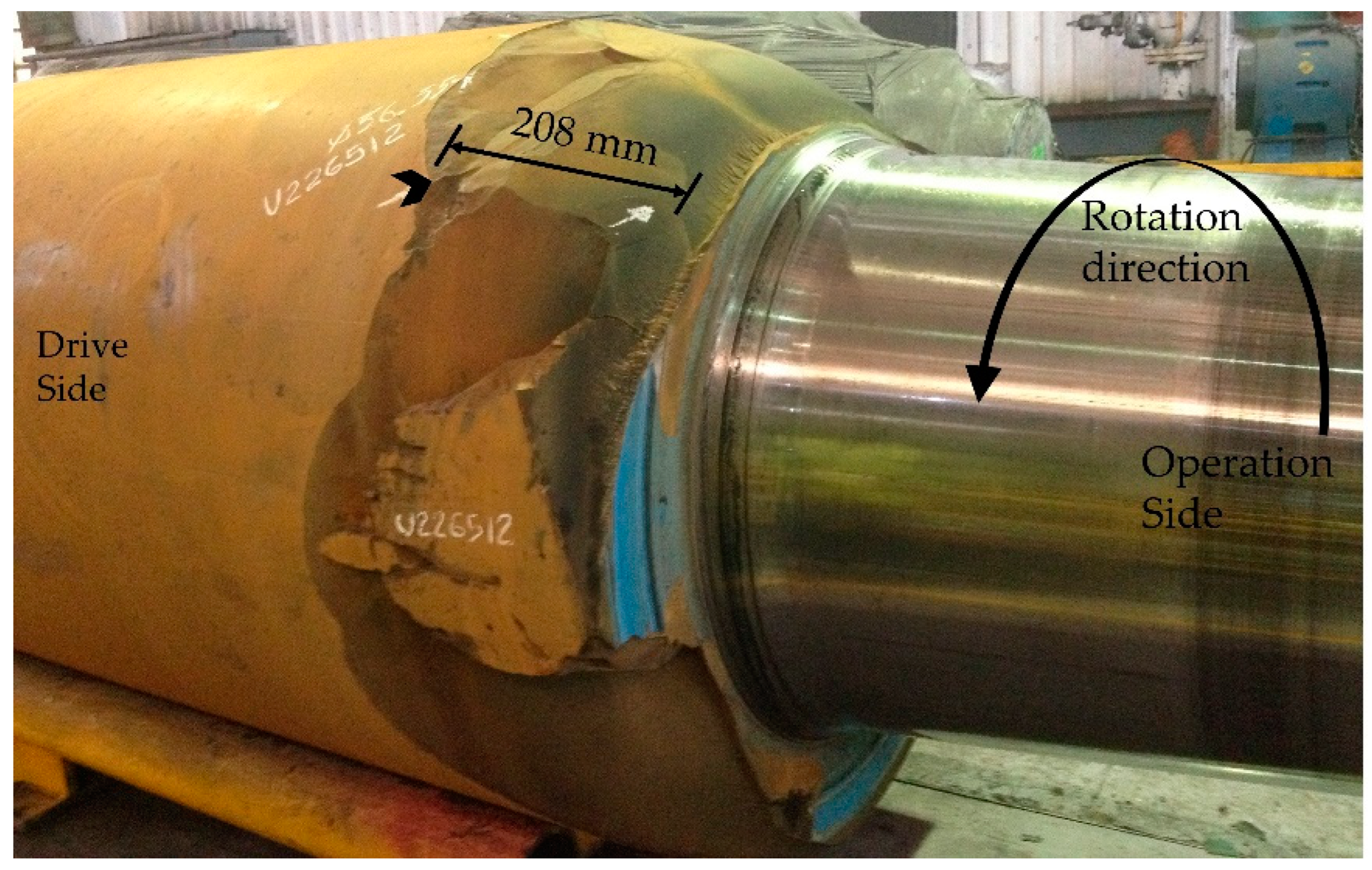
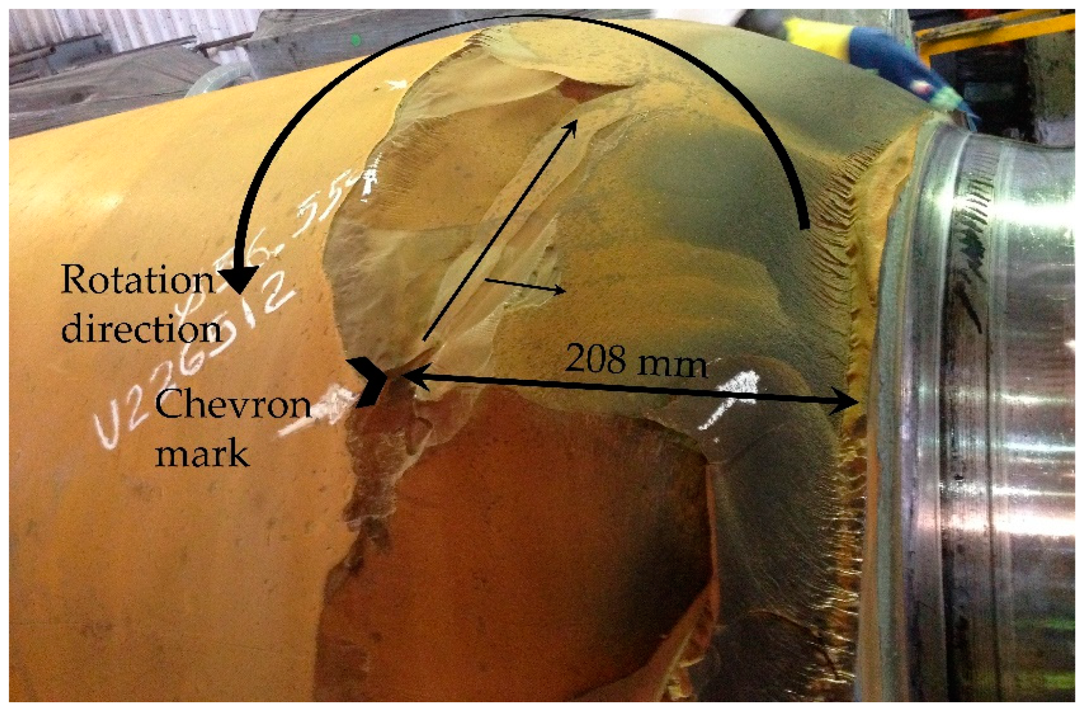
3.1. The Surface Morphology
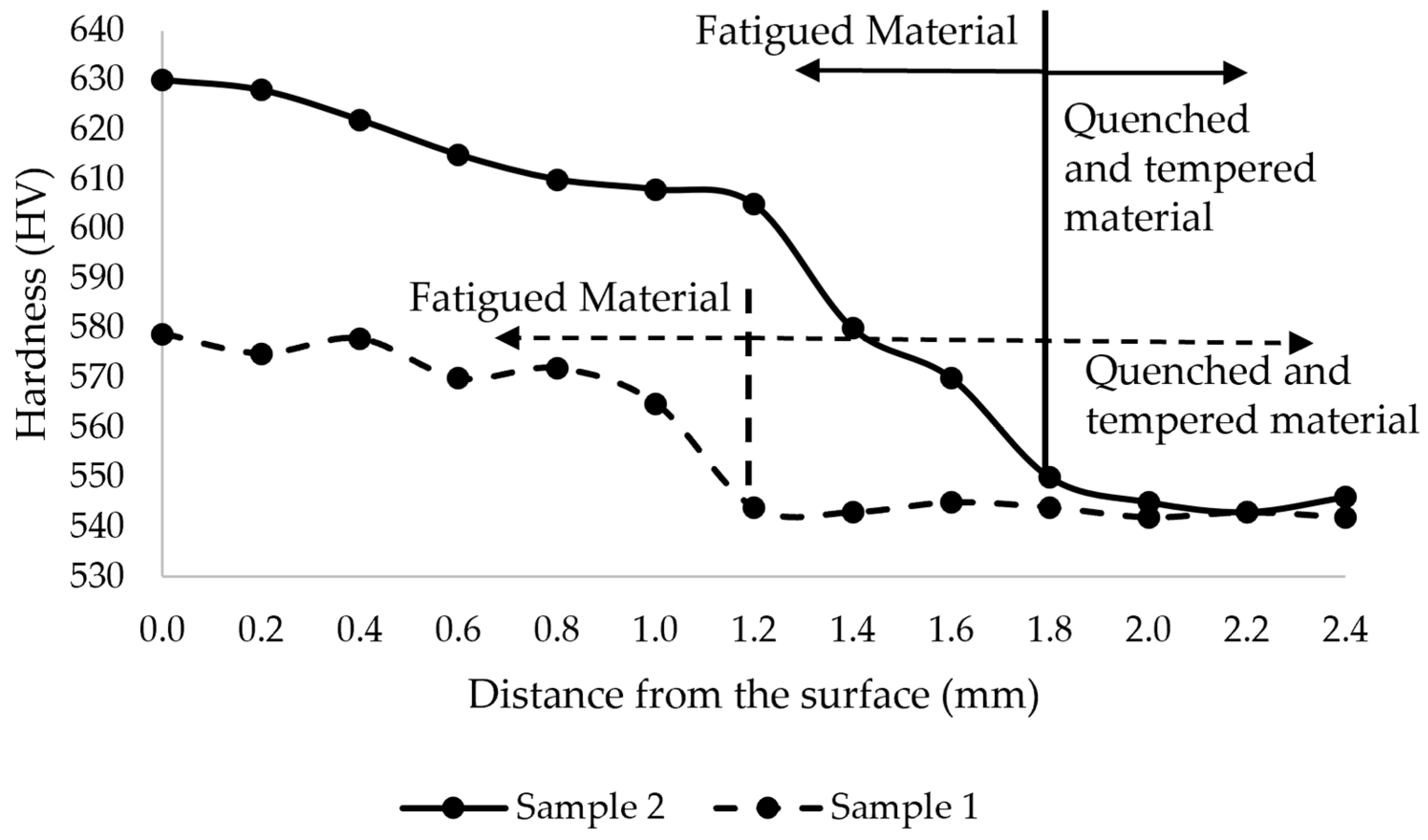
3.2. The Mechanical and Metallurgical Properties
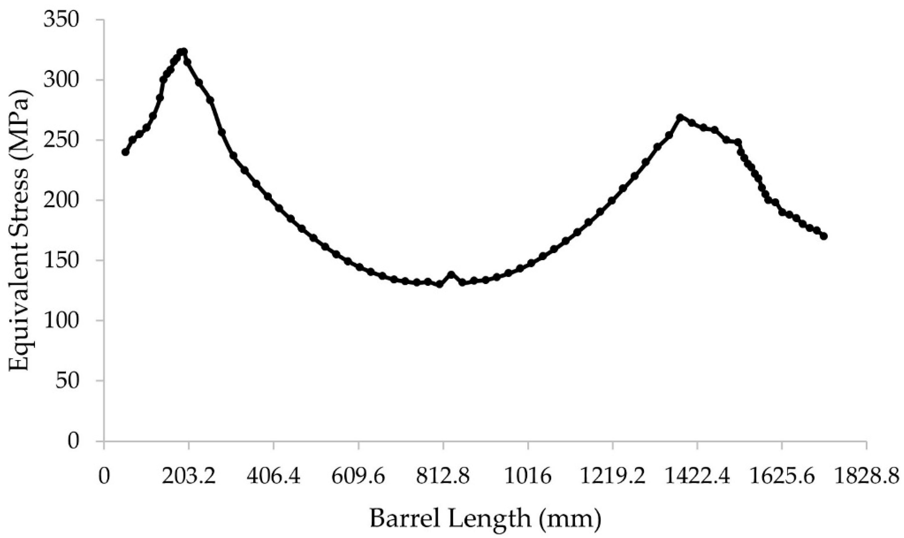
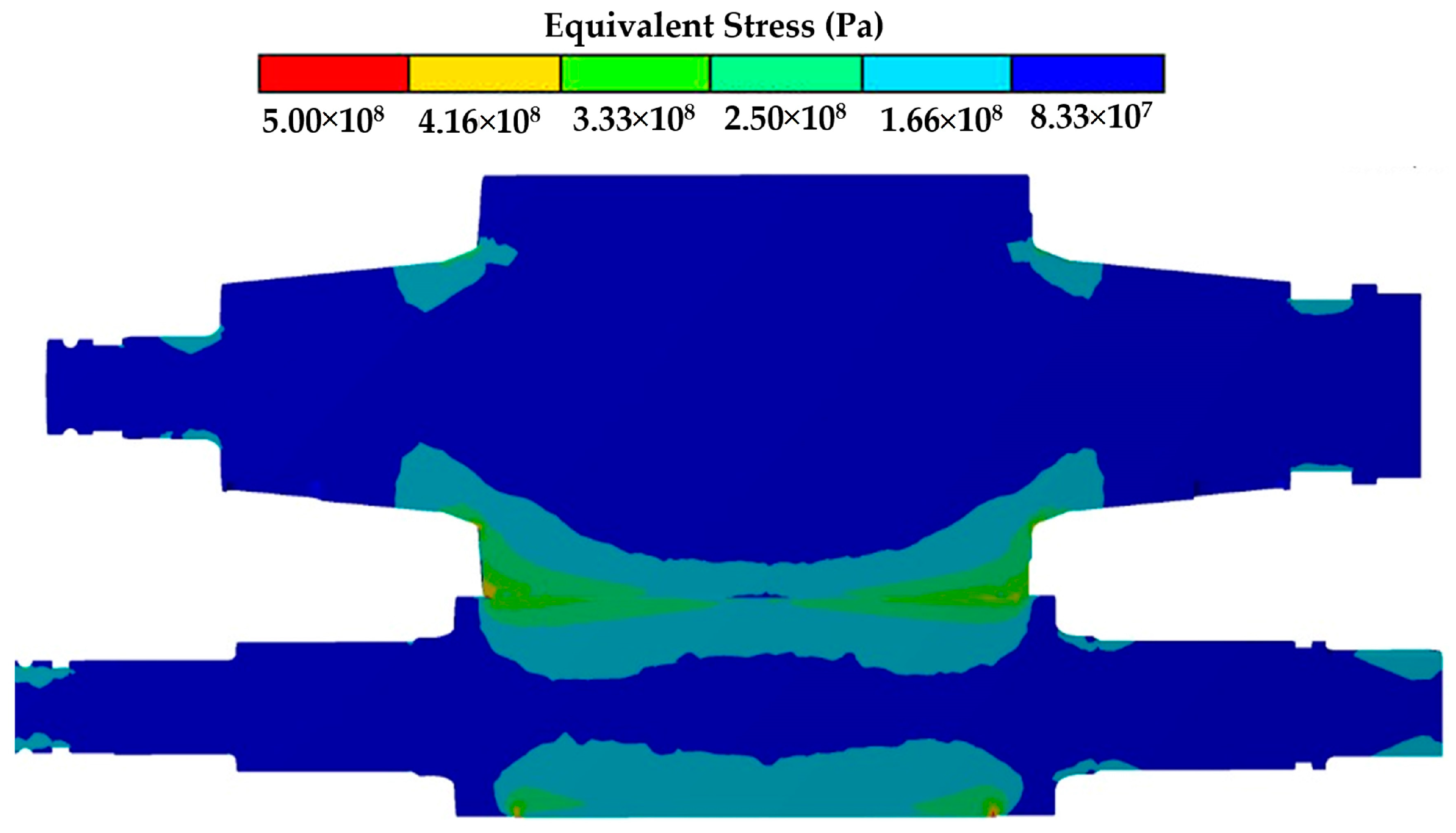
3.3. Stress Distribution Analyzed by FEM
4. Discussion
5. Conclusions
Author Contributions
Funding
Institutional Review Board Statement
Informed Consent Statement
Data Availability Statement
Acknowledgments
Conflicts of Interest
References
- Servin, R.; Garcia, A.M.; Mercado, R.; Vega, C.A. Development of Mathematical Model for Control Wear in Backup Roll for Hot Strip Mill. J. Iron. Steel. Res. Int. 2014, 21, 46–51. [Google Scholar] [CrossRef]
- Yang, G.; Cao, J.; Zhang, J.; Jia, S.; Tan, R. Backup roll contour of a SmartCrown tandem cold rolling mill. J. Univ. Sci. Technol. Beijing Miner. Met. Mater. 2008, 15, 357–361. [Google Scholar] [CrossRef]
- Li, H.-J.; Xu, J.-Z.; Wang, G.-D.; Shi, L.-J.; Xiao, Y. Development of strip flatness and crown control model for hot strip mills. J. Iron Steel Res. Int. 2010, 17, 21–27. [Google Scholar] [CrossRef]
- Wang, X.D.; Li, F.; Li, B.H.; Zhu, G.S.; Li, B.; Zhang, B.H. VCR back-up roll and negative work roll contour design for solving roll spalling and transfer bar profile problems in hot strip mill. Ironmak Steelmak. 2010, 633–640. [Google Scholar] [CrossRef]
- Wang, X.; Li, F.; Li, B.; Dong, L.; Zhang, B. Design and Application of an Optimum Backup Roll Contour Configured with CVC Work Roll in Hot Strip Mill. ISIJ Int. 2012, 52, 1637–1643. [Google Scholar] [CrossRef] [Green Version]
- Cao, J.-G.; Wei, G.-C.; Zhang, J.; Chen, X.-L.; Zhou, Y.-Z. VCR and ASR technology for profile and flatness control in hot strip mills. J. Central South Univ. Technol. 2008, 15, 264–270. [Google Scholar] [CrossRef]
- Liu, G.-M.; Li, Y.-G.; Huang, Q.-X.; Yang, X. Axial Force Analysis and Roll Contour Configuration of Four-High CVC Mill. Math. Probl. Eng. 2018, 2018, 9262067. [Google Scholar] [CrossRef] [Green Version]
- Liu, X.-H.; Shi, X.; Li, S.-Q.; Xu, J.-Y.; Wang, G.-D. FEM Analysis of Rolling Pressure Along Strip Width in Cold Rolling Process. J. Iron Steel Res. Int. 2007, 14, 22–26. [Google Scholar] [CrossRef]
- Zhang, G.-M.; Xiao, H.; Wang, C.-H. Three-Dimensional Model for Strip Hot Rolling. J. Iron Steel Res. Int. 2006, 13, 23–26. [Google Scholar] [CrossRef]
- Kong, N.; Cao, J.; Wang, Y.; Tieu, A.K.; Yang, L.; Hou, A.; Wang, Z. Development of Smart Contact Backup Rolls in Ultra-wide Stainless Strip Rolling Process. Mater. Manuf. Process. 2014, 29, 129–133. [Google Scholar] [CrossRef]
- Cao, J.-G.; Chai, X.-T.; Li, Y.-L.; Kong, N.; Jia, S.-H.; Zeng, W. Integrated design of roll contours for strip edge drop and crown control in tandem cold rolling mills. J. Mater. Process. Technol. 2018, 252, 432–439. [Google Scholar] [CrossRef]
- Dong, Q.; Cao, J.G.; Li, H.B.; Zhou, Y.S.; Yan, T.L.; Wang, W.Z. Analysis of Spalling in Roughing Mill Backup Rolls of Wide and Thin Strip Hot Rolling Process. Steel Res. Int. 2014, 86, 129–136. Available online: https://www.researchgate.net/publication/261726843 (accessed on 13 April 2022). [CrossRef]
- Qin, X.-F.; Sun, D.-L.; Xie, L.-Y.; Wu, Q. Hardening mechanism of Cr5 backup roll material induced by rolling contact fatigue. Mater. Sci. Eng. A 2014, 600, 195–199. [Google Scholar] [CrossRef]
- Choudhary, B.K.; Palaparti, D.P.R.; Samuel, E.I. Analysis of Tensile Stress-Strain and Work-Hardening Behavior in 9Cr-1Mo Ferritic Steel. Met. Mater Trans. A 2013, 44, 212–223. [Google Scholar] [CrossRef]
- Kocks, U.F. Laws for Work-Hardening and Low-Temperature Creep. J. Eng. Mater. Technol. 1976, 98, 76–85. [Google Scholar] [CrossRef]
- Sadeghi, F.; Jalalahmadi, B.; Slack, T.S.; Raje, N.; Arakere, N.K. A Review of Rolling Contact Fatigue. J. Tribol. 2009, 131, 041403. [Google Scholar] [CrossRef]
- El Laithy, M.; Wang, L.; Harvey, T.J.; Vierneusel, B.; Correns, M.; Blass, T. Further understanding of rolling contact fatigue in rolling element bearings—A review. Tribol. Int. 2019, 140, 105849. [Google Scholar] [CrossRef]
- Ringsberg, J.W. Life prediction of rolling contact fatigue crack initiation. Int. J. Fatigue 2001, 23, 575–586. [Google Scholar] [CrossRef]
- Halme, J.; Andersson, P. Rolling contact fatigue and wear fundamentals for rolling bearing diagnostics state of the art. P I Mech. Eng. J-J. Eng. 2016, 224, 377–393. [Google Scholar] [CrossRef]
- El Laithy, M.; Wang, L.; Harvey, T.J.; Vierneusel, B. Re-investigation of dark etching regions and white etching bands in SAE 52100 bearing steel due to rolling contact fatigue. Int. J. Fatigue 2020, 136, 105591. [Google Scholar] [CrossRef]
- Rosado, L.; Forster, N.H.; Thompson, K.L.; Cooke, J.W. Rolling Contact Fatigue Life and Spall Propagation of AISI M50, M50NiL, and AISI 52100, Part I: Experimental Results. Tribol. Trans. 2009, 53, 29–41. [Google Scholar] [CrossRef]
- ASM International. ASM Handbook, 1st ed.; ASM International: West Conshohocken, PA, USA, 2002; Volume 11. [Google Scholar]
- Naville, W.; Sachs, P.E. Practical Plant Failure Analysis, 1st ed.; CRC Press: New York, NY, USA, 2007. [Google Scholar]
- ASTM International. ASTM Volume 03.01 Metals—Mechanical testing, ASTM Compass; ASTM International: West Conshohocken, PA, USA, 2020. [Google Scholar]
- ASM International. ASM Handbook, Metals Handbook, 9th ed.; ASM International: West Conshohocken, PA, USA, 1987; Volume 12. [Google Scholar]
- Servin, R.; Arreola, S.A.; Calderón, I.; Perez, A.; Miguel, S.M.S. Effect of Crown Shape of Rolls on the Distribution of Stress and Elastic Deformation for Rolling Processes. Metals 2019, 9, 1222. [Google Scholar] [CrossRef] [Green Version]
- Serbino, E.M.; Tschiptschin, A.P. Fatigue behavior of bainitic and martensitic super clean Cr–Si high strength steels. Int. J. Fatigue 2014, 61, 87–92. [Google Scholar] [CrossRef]


| Mechanical Component | Value |
|---|---|
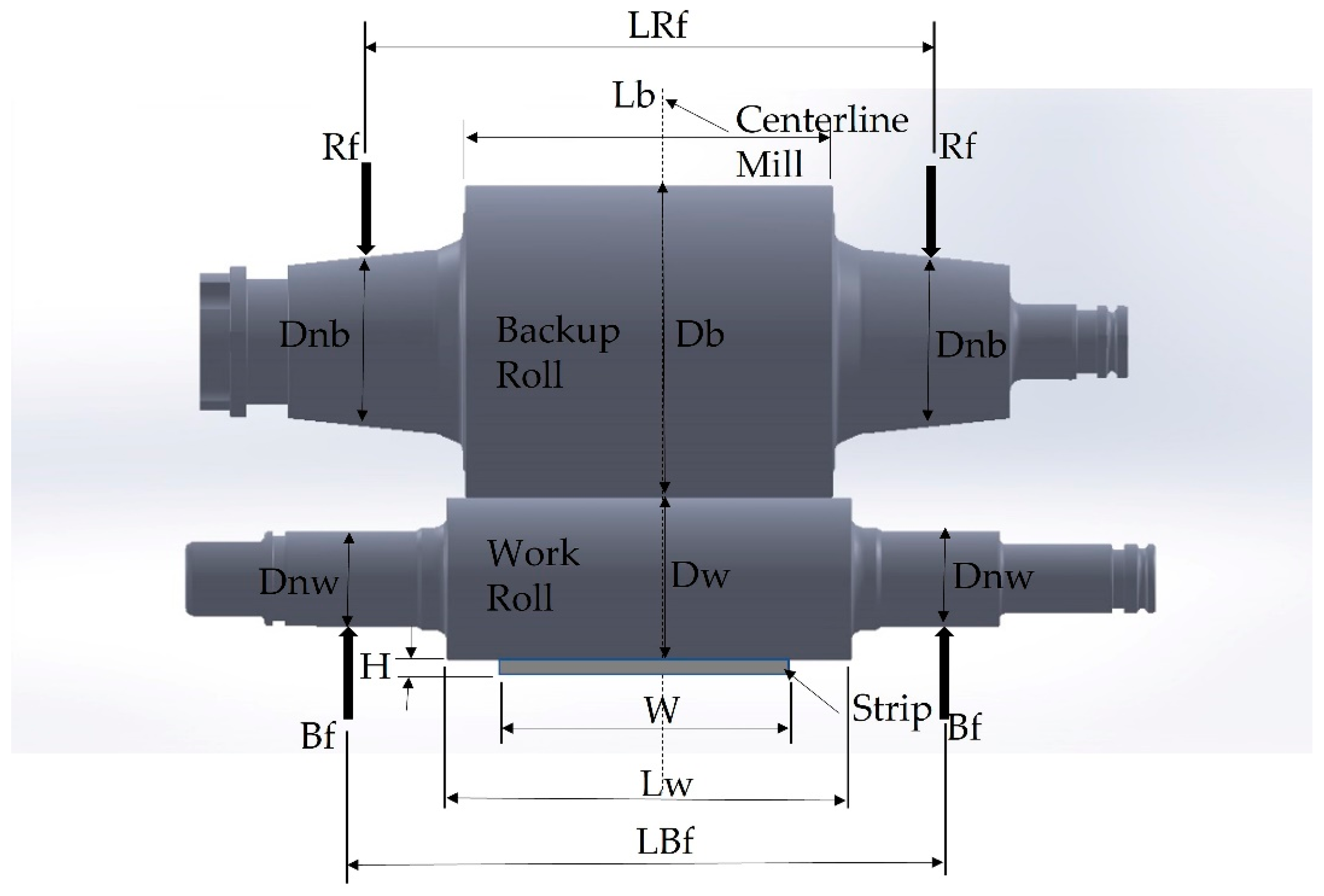
| Work roll diameter Dw | 625.475 mm |
| Work roll barrel length Lw | 1897.20 mm |
| Work roll neck diameter Dnw | 384.175 mm |
| Work roll Bending force length LBf | 2747.20 mm |
| Backup roll diameter Db | 1219.20 mm |
| Backup roll barrel length Lb | 1727.20 mm |
| Backup roll neck diameter Dnb | 678.49 mm |
| Backup roll Rolling force length LRf | 2717.80 mm |
| Strip width W | 1524.0 mm |
| Strip thickness H | 2.0 mm |
| Model Parameter | Value |
|---|---|
| Rolling force Rf | 36,000 kN |
| Bending force Bf | 350 kN |
| Work Roll Crown | 0.1016 mm |
| Backup Roll Crown | 0.0762 mm |
| Maximum Thermal crown WR | 0.150 mm |
| Maximum Thermal crown BUR | 0.100 mm |
| Maximum wear WR | 0.150 mm |
| Maximum wear BUR | 0.600 mm |
| Chamfer of BUR | 100 mm × 1.0 mm |
| Chamfer of WR | 100 mm × 2.8 mm |
| Mechanical Property | Value |
|---|---|
| Piosson’s ratio work roll | 0.3 |
| Poisson’s ratio backup roll | 0.3 |
| Young’s modulus work roll | 210 GPa |
| Young’s modulus backup roll | 220 GPa |
| Young’s modulus strip | 210 MPa |
| Chemical Composition (%Wt) | Mechanical Properties [1] | ||||||||
|---|---|---|---|---|---|---|---|---|---|
| C | Si | Mn | Cr | Mo | V | Yield Limit (MPa) | Hardness Range (HV) | Poisson ratio | Modulus Elasticity (GPa) |
| 0.55 | 0.15 | 0.60 | 5.37 | 0.80 | 0.15 | 1200 | 530–580 | 0.3 | 220 |
Publisher’s Note: MDPI stays neutral with regard to jurisdictional claims in published maps and institutional affiliations. |
© 2022 by the authors. Licensee MDPI, Basel, Switzerland. This article is an open access article distributed under the terms and conditions of the Creative Commons Attribution (CC BY) license (https://creativecommons.org/licenses/by/4.0/).
Share and Cite
Servin-Castañeda, R.; Arreola-Villa, S.A.; Perez-Alvarado, A.; Calderón-Ramos, I.; Torres-Gonzalez, R.; Martinez-Hurtado, A. Influence of Work Hardening on the Surface of Backup Rolls for a 4-High Rolling Mill Fractured during Rolling Campaign. Materials 2022, 15, 3524. https://doi.org/10.3390/ma15103524
Servin-Castañeda R, Arreola-Villa SA, Perez-Alvarado A, Calderón-Ramos I, Torres-Gonzalez R, Martinez-Hurtado A. Influence of Work Hardening on the Surface of Backup Rolls for a 4-High Rolling Mill Fractured during Rolling Campaign. Materials. 2022; 15(10):3524. https://doi.org/10.3390/ma15103524
Chicago/Turabian StyleServin-Castañeda, Rumualdo, Sixtos Antonio Arreola-Villa, Alejandro Perez-Alvarado, Ismael Calderón-Ramos, Ruben Torres-Gonzalez, and Alonso Martinez-Hurtado. 2022. "Influence of Work Hardening on the Surface of Backup Rolls for a 4-High Rolling Mill Fractured during Rolling Campaign" Materials 15, no. 10: 3524. https://doi.org/10.3390/ma15103524