
Basic Mechanism of Surface Topography Evolution in Electron Beam Based Additive Manufacturing


Abstract
:
1. Introduction
2. Materials and Methods
2.1. Experimental
2.2. Semi-Analytical Heat Conduction Model
3. Results
3.1. E-PBF Build Process
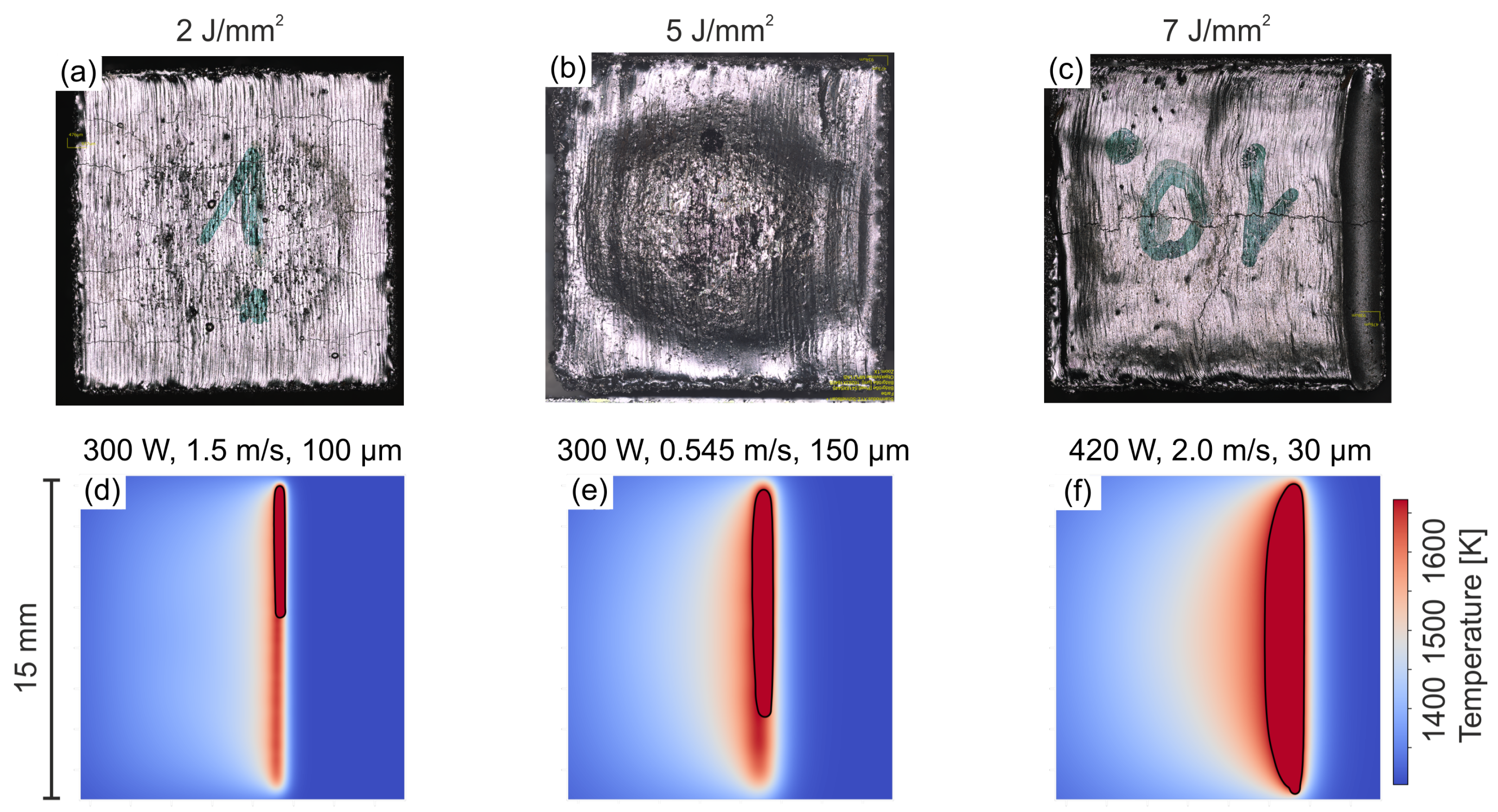
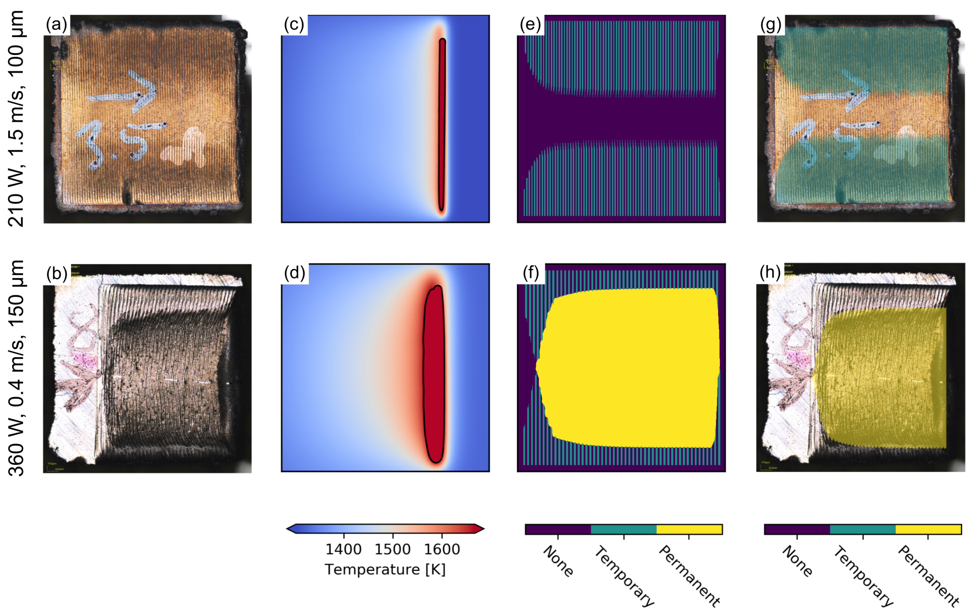
3.2. Single Layer Remelting
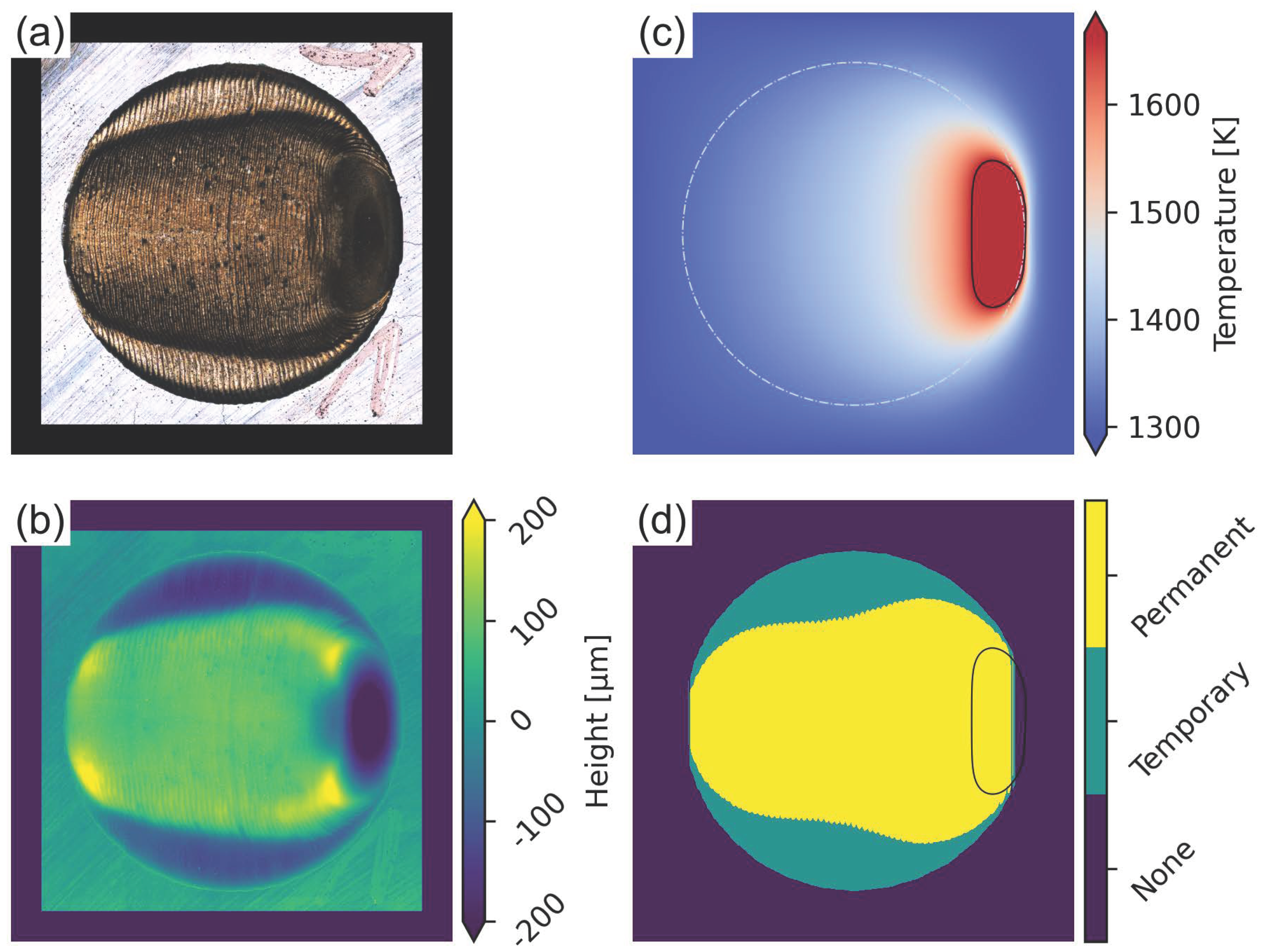
Complex Geometry
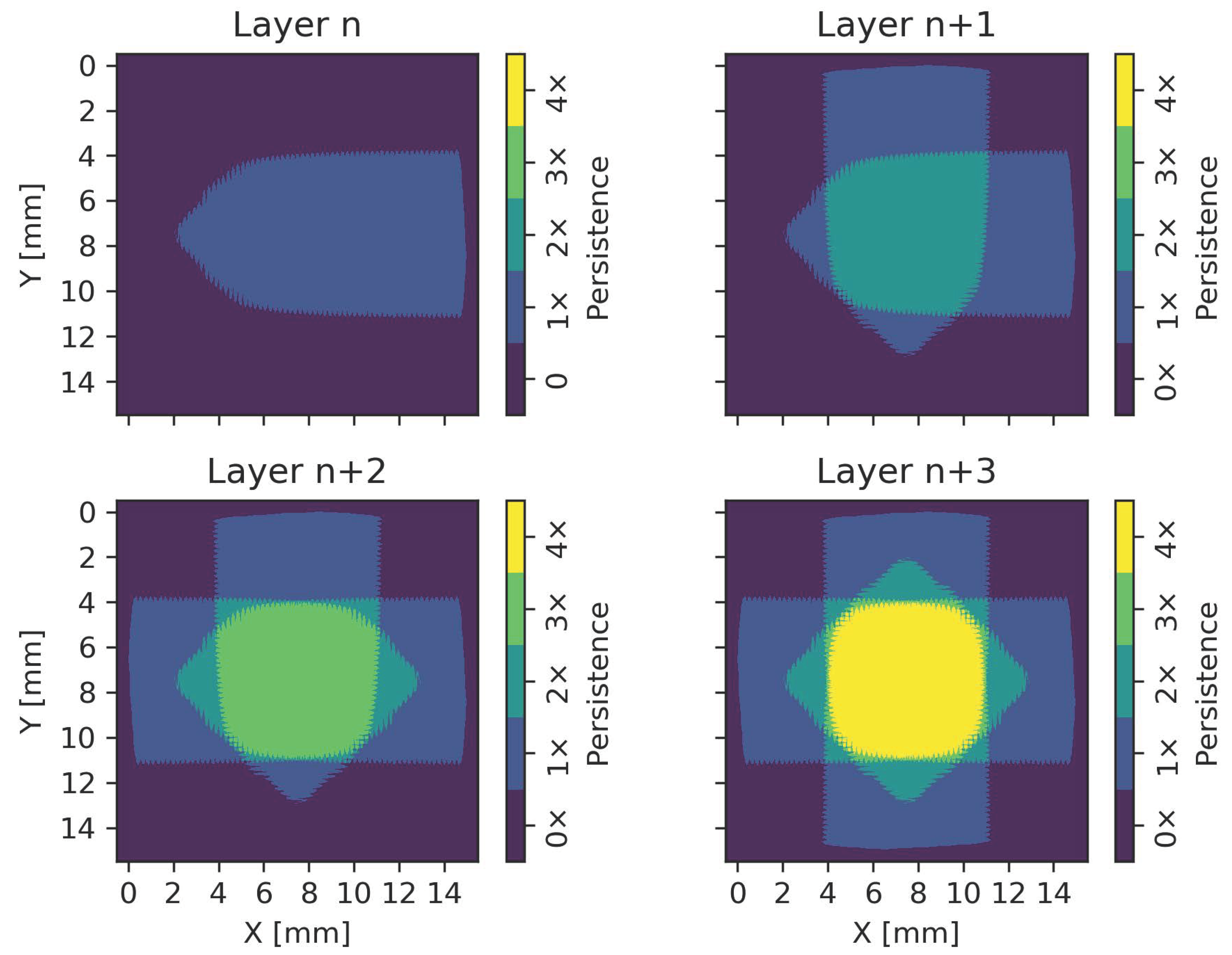
3.3. Hatch Rotation
4. Discussion
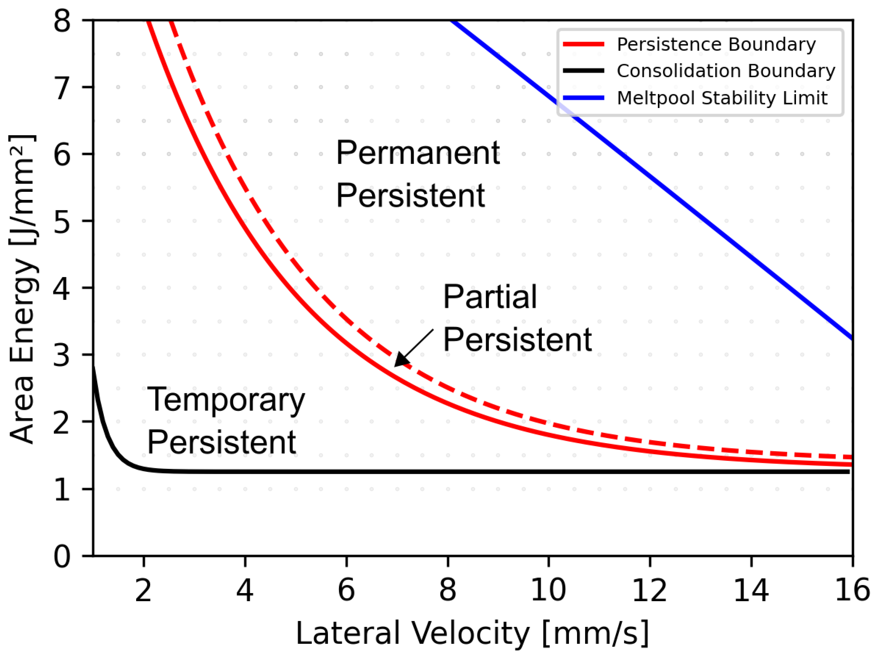
Process Window and Prevention Strategies
5. Conclusions
Author Contributions
Funding
Institutional Review Board Statement
Informed Consent Statement
Data Availability Statement
Conflicts of Interest
References
- Körner, C. Additive manufacturing of metallic components by selective electron beam melting—A review. Int. Mater. Rev. 2016, 61, 361–377. [Google Scholar] [CrossRef] [Green Version]
- Gu, D.D.; Meiners, W.; Wissenbach, K.; Poprawe, R. Laser additive manufacturing of metallic components: Materials, processes and mechanisms. Int. Mater. Rev. 2012, 57, 133–164. [Google Scholar] [CrossRef]
- Vayre, B.; Vignat, F.; Villeneuve, F. Metallic additive manufacturing: State-of-the-art review and prospects. Mech. Ind. 2012, 13, 89–96. [Google Scholar] [CrossRef]
- Wong, K.V.; Hernandez, A. A Review of Additive Manufacturing. ISRN Mech. Eng. 2012, 2012, 208760. [Google Scholar] [CrossRef] [Green Version]
- Frazier, W.E. Metal Additive Manufacturing: A Review. J. Mater. Eng. Perform. 2014, 23, 1917–1928. [Google Scholar] [CrossRef]
- Murr, L.E.; Martinez, E.; Amato, K.N.; Gaytan, S.M.; Hernandez, J.; Ramirez, D.A.; Shindo, P.W.; Medina, F.; Wicker, R.B. Fabrication of Metal and Alloy Components by Additive Manufacturing: Examples of 3D Materials Science. J. Mater. Res. Technol. 2012, 1, 42–54. [Google Scholar] [CrossRef] [Green Version]
- Gong, X.; Anderson, T.; Chou, K. Review on powder-based electron beam additive manufacturing technology. Manuf. Rev. 2014, 1, 2. [Google Scholar] [CrossRef]
- Markl, M.; Ammer, R.; Rüde, U.; Körner, C. Numerical investigations on hatching process strategies for powder-bed-based additive manufacturing using an electron beam. Int. J. Adv. Manuf. Technol. 2014, 78, 239–247. [Google Scholar] [CrossRef] [Green Version]
- Helmer, H.E.; Körner, C.; Singer, R.F. Additive manufacturing of nickel-based superalloy Inconel 718 by selective electron beam melting: Processing window and microstructure. J. Mater. Res. 2014, 29, 1987–1996. [Google Scholar] [CrossRef]
- Bauereiß, A.; Scharowsky, T.; Körner, C. Defect generation and propagation mechanism during additive manufacturing by selective beam melting. J. Mater. Process. Technol. 2014, 214, 2522–2528. [Google Scholar] [CrossRef]
- Tammas-Williams, S.; Zhao, H.; Léonard, F.; Derguti, F.; Todd, I.; Prangnell, P.B. XCT analysis of the influence of melt strategies on defect population in Ti–6Al–4V components manufactured by Selective Electron Beam Melting. Mater. Charact. 2015, 102, 47–61. [Google Scholar] [CrossRef]
- Juechter, V.; Scharowsky, T.; Singer, R.F.; Körner, C. Processing window and evaporation phenomena for Ti–6Al–4V produced by selective electron beam melting. Acta Mater. 2014, 76, 252–258. [Google Scholar] [CrossRef] [Green Version]
- Guo, C.; Ge, W.; Lin, F. Effects of scanning parameters on material deposition during Electron Beam Selective Melting of Ti-6Al-4V powder. J. Mater. Process. Technol. 2015, 217, 148–157. [Google Scholar] [CrossRef]
- Rausch, A.M.; Küng, V.E.; Pobel, C.; Markl, M.; Körner, C. Predictive Simulation of Process Windows for Powder Bed Fusion Additive Manufacturing: Influence of the Powder Bulk Density. Materials 2017, 10, 1117. [Google Scholar] [CrossRef] [Green Version]
- Amara, E.H.; Fabbro, R.; Hamadi, F. Modeling of the melted bath movement induced by the vapor flow in deep penetration laser welding. J. Laser Appl. 2006, 18, 2–11. [Google Scholar] [CrossRef]
- Pearson, J.R.A. On convection cells induced by surface tension. J. Fluid Mech. 1958, 4, 489–500. [Google Scholar] [CrossRef]
- Platten, J.K.; Villers, D. An introduction to thermocapillary convection. In Wetting Phenomena; Coninck, J.D., Ed.; Lecture Notes in Physics; Springer: Berlin/Heidelberg, Germany, 1990; Volume 354, pp. 69–77. [Google Scholar] [CrossRef]
- Klassen, A.; Forster, V.E.; Juechter, V.; Körner, C. Numerical simulation of multi-component evaporation during selective electron beam melting of TiAl. J. Mater. Process. Technol. 2017, 247, 280–288. [Google Scholar] [CrossRef]
- Klassen, A. Simulation of Evaporation Phenomena in Selective Electron Beam Melting. Ph.D. Thesis, Friedrich-Alexander-Universität Erlangen-Nürnberg, Erlangen, Germany, 2018. [Google Scholar]
- Semak, V.; Matsunawa, A. The role of recoil pressure in energy balance during laser materials processing. J. Phys. D Appl. Phys. 1997, 30, 2541–2552. [Google Scholar] [CrossRef]
- Plotkowski, A.; Kirka, M.M.; Babu, S.S. Verification and validation of a rapid heat transfer calculation methodology for transient melt pool solidification conditions in powder bed metal additive manufacturing. Addit. Manuf. 2017, 18, 256–268. [Google Scholar] [CrossRef]
- Pistor, J.; Breuning, C.; Körner, C. A single crystal process window for electron beam powder bed fusion additive manufacturing of a cmsx-4 type ni-based superalloy. Materials 2021, 14, 3785. [Google Scholar] [CrossRef]
- Pistor, J.; Körner, C. Formation of topologically closed packed phases within CMSX-4 single crystals produced by additive manufacturing. Mater. Lett. X 2019, 1, 100003. [Google Scholar] [CrossRef]
- Körner, C.; Ramsperger, M.; Meid, C.; Bürger, D.; Wollgramm, P.; Bartsch, M.; Eggeler, G. Microstructure and Mechanical Properties of CMSX-4 Single Crystals Prepared by Additive Manufacturing. Metall. Mater. Trans. A 2018, 9, 297. [Google Scholar] [CrossRef] [Green Version]
- Ramsperger, M.; Körner, C. Selective electron beam melting of the single crystalline nickel-base superalloy CMSX-4®: From columnar grains to a single crystal. In Superalloys 2016: Proceedings of the 13th International Symposium on Superalloys; Wiley: New York, NY, USA, 2016; Volume 214, pp. 341–349. [Google Scholar] [CrossRef]
- Rausch, A.M.; Pistor, J.; Breuning, C.; Markl, M.; Körner, C. New grain formation mechanisms during powder bed fusion. Materials 2021, 14, 3324. [Google Scholar] [CrossRef] [PubMed]
- Nguyen, N.T.; Ohta, A.; Matsuoka, K.; Suzuki, N.; Maeda, Y. Analytical solutions for transient temperature of semi-infinite body subjected to 3-D moving heat sources. Weld. J. 1999, 8, 265–274. [Google Scholar]
- Stump, B.; Plotkowski, A. An adaptive integration scheme for heat conduction in additive manufacturing. Appl. Math. Model. 2019, 75, 787–805. [Google Scholar] [CrossRef]
- Gruber, H.; Luchian, C.; Hryha, E.; Nyborg, L. Effect of Powder Recycling on Defect Formation in Electron Beam Melted Alloy 718. Metall. Mater. Trans. A 2020, 51, 2430–2443. [Google Scholar] [CrossRef] [Green Version]
- Aune, R.E.; Battezzati, L.; Brooks, R.; Egry, I.; Fecht, H.J.; Garandet, J.P.; Hayashi, M.; Mills, K.C.; Passerone, A.; Quested, P.N.; et al. Thermophysical properties of IN738LC, MM247LC and CMSX-4 in the liquid and high temperature solid phase. In Proceedings of the International Symposium on Superalloys and Various Derivatives, Pittsburgh, PA, USA, 2–5 October 2005; pp. 467–476. [Google Scholar] [CrossRef]
- Aune, R.; Battezzati, L.; Brooks, R.; Egry, I.; Fecht, H.J.; Garandet, J.P.; Mills, K.C.; Passerone, A.; Quested, P.N.; Ricci, E.; et al. Measurement of thermophysical properties of liquid metallic alloys in a ground- and microgravity based research programme—The ThermoLab project. Microgravity Sci. Technol. 2005, 15, 7–10. [Google Scholar] [CrossRef]
- Lee, J.; Shimoda, W.; Tanaka, T. Surface tension and its temperature coefficient of liquid Sn-X (X=Ag, Cu) alloys. Mater. Trans. 2004, 45, 2864–2870. [Google Scholar] [CrossRef] [Green Version]
- Marangoni, C. Ueber die Ausbreitung der Tropfen einer Flüssigkeit auf der Oberfläche einer anderen. Ann. Der Phys. 1871, 219, 337–354. [Google Scholar] [CrossRef] [Green Version]
- Yan, W.; Ge, W.; Qian, Y.; Lin, S.; Zhou, B.; Liu, W.K.; Lin, F.; Wagner, G.J. Multi-physics modeling of single/multiple-track defect mechanisms in electron beam selective melting. Acta Mater. 2017, 134, 324–333. [Google Scholar] [CrossRef]
- Shrestha, S.; Chou, K. A build surface study of Powder-Bed Electron Beam Additive Manufacturing by 3D thermo-fluid simulation and white-light interferometry. Int. J. Mach. Tools Manuf. 2017, 121, 37–49. [Google Scholar] [CrossRef]
- Breuning, C.; Arnold, C.; Markl, M.; Körner, C. A multivariate meltpool stability criterion for fabrication of complex geometries in electron beam powder bed fusion. Addit. Manuf. 2021, 45, 102051. [Google Scholar] [CrossRef]


| Property | Value |
|---|---|
| Thermal diffusivity (m2 s−1) | |
| Density (kg m−3) | 8193 |
| Specific heat (J kg−1 K−1) | 925 |
| Absorption coefficient | |
| Preheat temperature () | 1273 |
| Liquidus temperature () | 1667 |
Publisher’s Note: MDPI stays neutral with regard to jurisdictional claims in published maps and institutional affiliations. |
© 2022 by the authors. Licensee MDPI, Basel, Switzerland. This article is an open access article distributed under the terms and conditions of the Creative Commons Attribution (CC BY) license (https://creativecommons.org/licenses/by/4.0/).
Share and Cite
Breuning, C.; Pistor, J.; Markl, M.; Körner, C. Basic Mechanism of Surface Topography Evolution in Electron Beam Based Additive Manufacturing. Materials 2022, 15, 4754. https://doi.org/10.3390/ma15144754
Breuning C, Pistor J, Markl M, Körner C. Basic Mechanism of Surface Topography Evolution in Electron Beam Based Additive Manufacturing. Materials. 2022; 15(14):4754. https://doi.org/10.3390/ma15144754
Chicago/Turabian StyleBreuning, Christoph, Julian Pistor, Matthias Markl, and Carolin Körner. 2022. "Basic Mechanism of Surface Topography Evolution in Electron Beam Based Additive Manufacturing" Materials 15, no. 14: 4754. https://doi.org/10.3390/ma15144754
APA StyleBreuning, C., Pistor, J., Markl, M., & Körner, C. (2022). Basic Mechanism of Surface Topography Evolution in Electron Beam Based Additive Manufacturing. Materials, 15(14), 4754. https://doi.org/10.3390/ma15144754