
High Pressure (HP) in Spark Plasma Sintering (SPS) Processes: Application to the Polycrystalline Diamond


Abstract
:1. Introduction
- −
- −
- −
- −
- to allow the sintering beyond the thermal decomposition temperature by the condensation effect, i.e., pressure stabilizing structure (ex: MgB2), e.g., [16];
- −
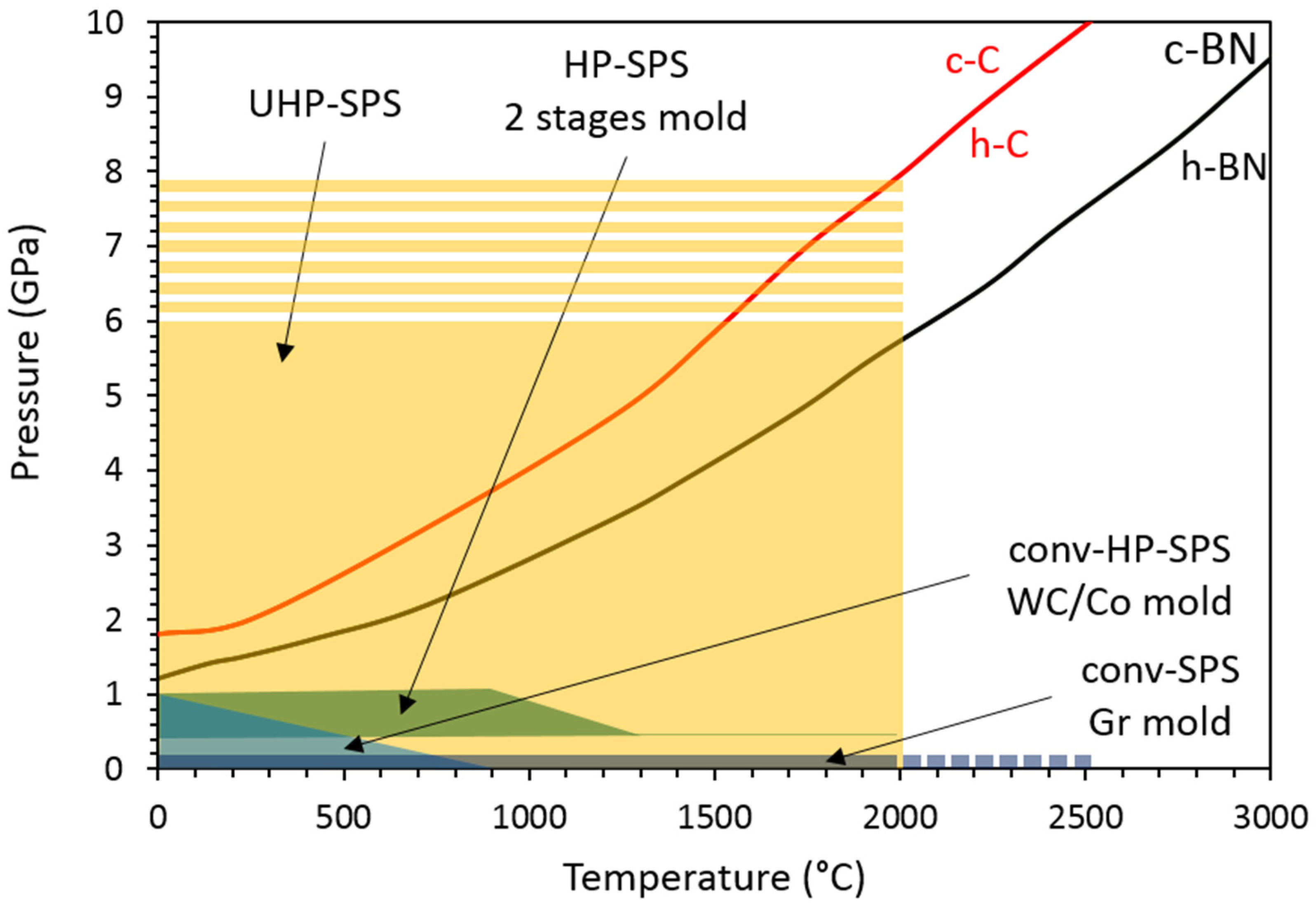
- to sinter the high-pressure stable phase in the high-pressure stability domain (ex: c-C, c-BN), e.g., [17];
- −
- to adjust the porosity, close to 0% (ex: transparent ceramics) or high porosity (p > 50%) (ex: bone structure mimetic), e.g., [18];
- −
- to increase the thermal stability of precursors by condensation effect by avoiding the departure of OH−, H2O, others volatile elements) [19];
- −
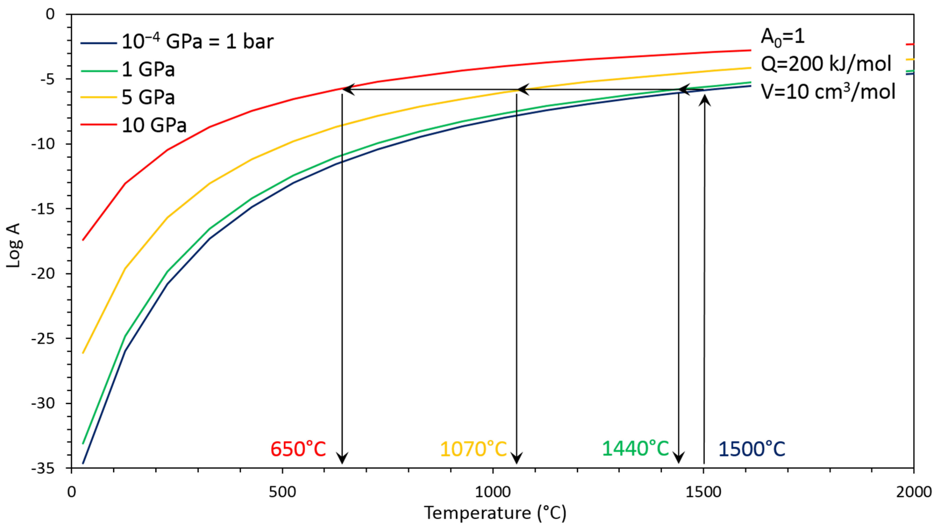
- to decrease the sintering/consolidation/densification temperature by its driving force in order to avoid grain growth (which is always activated by high temperature), e.g., [20];
- −
- to favor the structural phase existing only at lower temperature (ex for amorphous calcium phosphate), e.g., [21];
- −
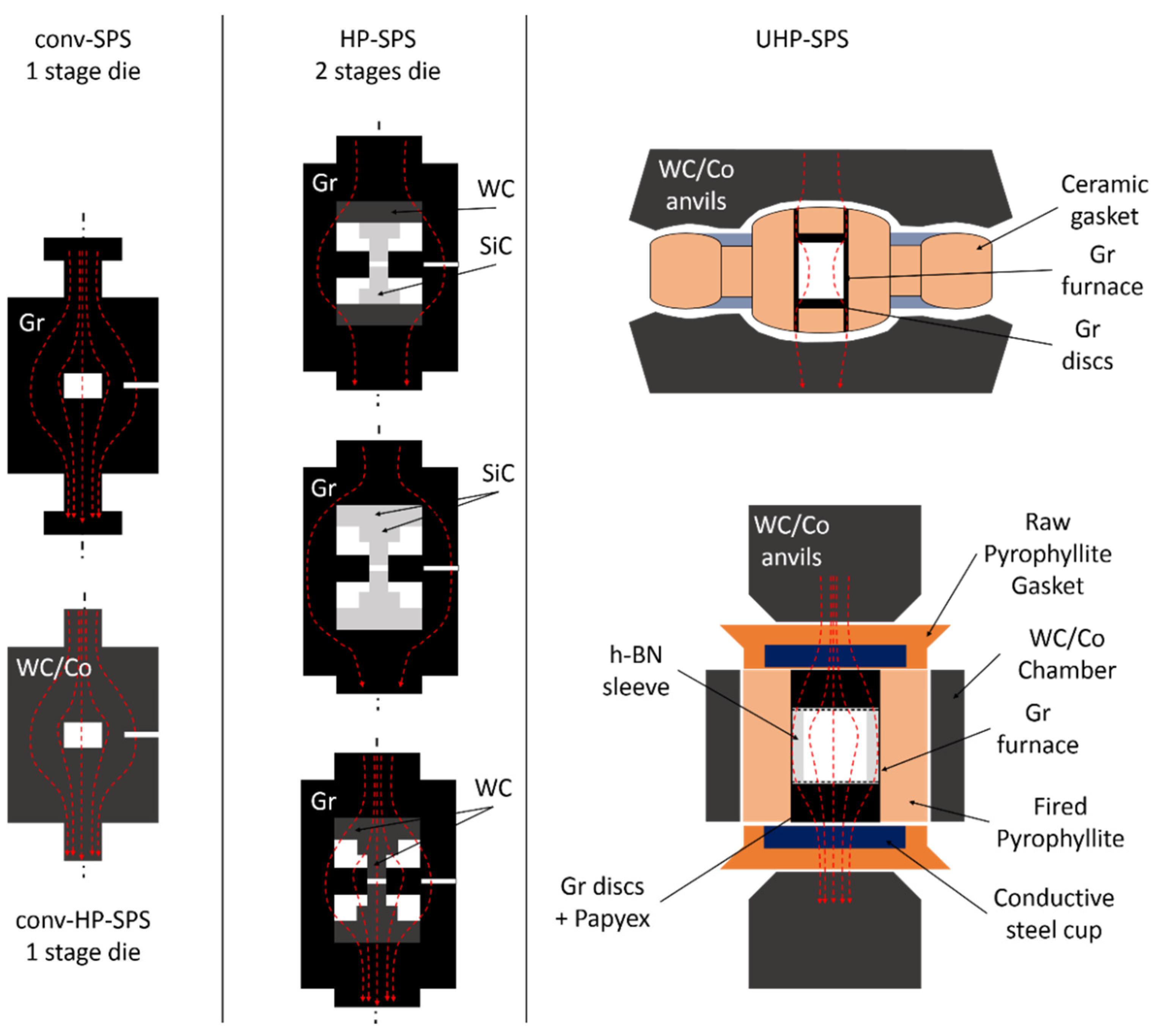
2. Development of High Pressure SPS (HP-SPS) Using Conventional Equipment
3. Recent Developments: UHP-SPS
4. Application to Binderless Diamond Sintering
4.1. Brief History of Binderless Diamond Sintering
4.2. UHP-SPS Setup with Belt-Type HP Apparatus for the Sintering of Diamond Powders
5. Conclusions
Author Contributions
Funding
Institutional Review Board Statement
Informed Consent Statement
Data Availability Statement
Acknowledgments
Conflicts of Interest
References
- Inoue, K. Electric Discharge Sintering. U.S. Patent No. 3,241,956, 22 March 1966. [Google Scholar]
- Inoue, K. Apparatus for Electrically Sintering Discrete Bodies. U.S. Patent No. 3,250,892, 10 May 1966. [Google Scholar]
- Grasso, S.; Sakka, Y.; Maizza, G. Electric current activated/assisted sintering (ECAS): A review of patents 1906–2008. Sci. Technol. Adv. Mater. 2009, 10, 053001. [Google Scholar] [CrossRef] [PubMed]
- Tokita, M. Progress of Spark Plasma Sintering (SPS) Method, Systems, Ceramics Applications and Industrialization. Ceramics 2021, 4, 160–198. [Google Scholar] [CrossRef]
- Guignard, J.; Bystricky, M.; Béjina, F. Dense fine-grained aggregates prepared by spark plasma sintering (SPS), an original technique in experimental petrology. Eur. J. Miner. 2011, 23, 323–331. [Google Scholar] [CrossRef]
- Chaim, R. Densification mechanisms in spark plasma sintering of nanocrystalline ceramics. Mater. Sci. Eng. A 2007, 443, 25–32. [Google Scholar] [CrossRef]
- Chaim, R.; Marder, R.; Estournés, C.; Shen, Z. Densification and preservation of ceramic nanocrystalline character by spark plasma sintering. Adv. Appl. Ceram. 2012, 111, 280–285. [Google Scholar] [CrossRef] [Green Version]
- Demuynck, M.; Erauw, J.-P.; Van der Biest, O.; Delannay, F.; Cambier, F. Densification of alumina by SPS and HP: A comparative study. J. Eur. Ceram. Soc. 2012, 32, 1957–1964. [Google Scholar] [CrossRef]
- Demazeau, G. High Pressure and Chemical Bonding in Materials Chemistry. Zeit. Nat. B 2006, 61, 799–807. [Google Scholar] [CrossRef]
- Liander, H.; Lundald, E. Some observations on the synthesis of diamonds. Ark. Kemi 1961, 16, 139–149. [Google Scholar]
- Bundy, F.P.; Hall, H.T.; Strong, H.M.; Wentorf, R.H., Jr. Man-made diamonds. Nature 1955, 176, 51–55. [Google Scholar] [CrossRef]
- Liao, S.-C.; Chen, Y.-J.; Kear, B.H.; Mayo, W.E. High pressure/low temperature sintering of nanocrystalline alumina. Nanostruct. Mater. 1998, 10, 1063–1079. [Google Scholar] [CrossRef]
- Liao, S.-C.; Chen, Y.-J.; Mayo, W.E.; Kear, B.H. Transformation-assisted consolidation of bulk nanocrystalline TiO2. Nanostruct. Mater. 1999, 11, 553–557. [Google Scholar] [CrossRef]
- Ma, D.; Kou, Z.; Liu, Y.; Wang, Y.; Gao, S.; Luo, X.; Li, W.; Wang, Y.; Du, Y.; Lei, L. Sub-micron binderless tungsten carbide sintering behavior under high pressure and high temperature. Int. J. Refract. Met. Mater. 2016, 54, 427–432. [Google Scholar] [CrossRef]
- Gao, J.; Wang, D.; Lei, L.; Zhang, F.; Zhang, J.; Fu, Z. High-pressure Sintering of Boron Carbide-Titanium Diboride Composites and Its Densification Mechanism. Adv. Mater. 2020, 35, 356–362. [Google Scholar] [CrossRef]
- Prakasam, M.; Balima, F.; Noudem, J.; Largeteau, A. Dense MgB2 Ceramics by Ultrahigh Pressure Field-Assisted Sintering. Ceramics 2020, 3, 521–532. [Google Scholar] [CrossRef]
- Hall, H.T. Sintered Diamond: A Synthetic Carbonado. Science 1970, 169, 868–869. [Google Scholar] [CrossRef] [PubMed]
- Wang, J.; Shaw, L.L. Transparent nanocrystalline hydroxyapatite by pressure-assisted sintering. Scr. Mater. 2010, 63, 593–596. [Google Scholar] [CrossRef]
- Nisr, C.; Chen, H.; Leinenweber, K.; Chizmeshya, A.; Prakapenka, V.B.; Prescher, C.; Tkachev, S.N.; Meng, Y.; Liu, Z.; Shim, S.-H. Large H2O solubility in dense silica and its implications for the interiors of water-rich planets. Proc. Natl. Acad. Sci. USA 2020, 117, 9747–9754. [Google Scholar] [CrossRef]
- Liu, L.; Li, X.; He, Q.; Xu, L.; Cao, X.; Peng, X.; Meng, C.; Wang, W.; Zhu, W.; Wang, Y. Sintering dense boron carbide without grain growth under high pressure. J. Am. Ceram. Soc. 2018, 101, 1289–1297. [Google Scholar] [CrossRef]
- Rubenis, K.; Zemjane, S.; Vecstaudza, J.; Bitenieks, J.; Locs, J. Densification of amorphous calcium phosphate using principles of the cold sintering process. J. Eur. Ceram. Soc. 2021, 41, 912–919. [Google Scholar] [CrossRef]
- Sébileau, J.-C.; Lemonnier, S.; Barraud, E.; Vallat, M.-F.; Carradò, A.; Nardin, M. Effects of pressure on poly(ether-ether-ketone) (PEEK) sintering mechanisms. J. Appl. Polym. Sci. 2019, 136, 47645. [Google Scholar] [CrossRef]
- Adesina, O.T.; Sadiku, E.R.; Adesina, O.S.; Ogunbiyi, O.F.; Jamiru, T.; Obadele, B.A. Spark plasma sintering of polymer and polymer-based composites: A review. Int. J. Adv. Manuf. Technol. 2021, 116, 759–775. [Google Scholar] [CrossRef]
- Munir, Z.A.; Anselmi-Tamburini, U.; Ohyanagi, M. The effect of electric field and pressure on the synthesis and consolidation of materials: A review of the spark plasma sintering method. J. Mater. Sci. 2006, 41, 763–777. [Google Scholar] [CrossRef]
- Hungria, T.; Galy, J.; Castro, A. Spark Plasma Sintering as a Useful Technique to the Nanostructuration of Piezo-Ferroelectric Materials. Adv. Eng. Mater. 2009, 11, 615–631. [Google Scholar] [CrossRef]
- Anselmi-Tamburini, U.; Garay, J.E.; Munir, Z.A. Fast low-temperature consolidation of bulk nanometric ceramic materials. Scr. Mater. 2006, 54, 823–828. [Google Scholar] [CrossRef]
- Zhang, H.B.; Kim, B.-N.; Morita, K.; Yoshida, H.; Lim, J.-H.; Hiraga, K. Optimization of high-pressure sintering of transparent zirconia with nano-sized grains. J. Alloys Compd. 2010, 508, 196–199. [Google Scholar] [CrossRef]
- Ghanizadeh, S.; Grasso, S.; Ramanujam, P.; Vaidhyanathan, B.; Binner, J.; Brown, P.; Goldwasser, J. Improved transparency and hardness in α-alumina ceramics fabricated by high-pressure SPS of nanopowders. Ceram. Int. 2017, 43, 275–281. [Google Scholar] [CrossRef] [Green Version]
- Sokol, M.; Kalabukhov, S.; Dariel, M.P.; Frage, N. High-pressure spark plasma sintering (SPS) of transparent polycrystalline magnesium aluminate spinel (PMAS). J. Eur. Ceram. Soc. 2014, 34, 4305–4310. [Google Scholar] [CrossRef]
- Sokol, M.; Halabi, M.; Mordekovitz, Y.; Kalabukhov, S.; Hayun, S.; Frage, N. An inverse Hall-Petch relation in nanocrystalline MgAl2O4 spinel consolidated by high pressure spark plasma sintering (HPSPS). Scr. Mater. 2017, 139, 159–161. [Google Scholar] [CrossRef]
- Ratzker, B.; Wagner, A.; Sokol, M.; Kalabukhov, S.; Dariel, M.P.; Frage, N. Optical and mechanical properties of transparent alumina fabricated by high-pressure spark plasma sintering. J. Eur. Ceram. Soc. 2019, 39, 2712–2719. [Google Scholar] [CrossRef]
- Grasso, S.; Kim, B.-N.; Hu, C.; Maizza, G.; Sakka, Y. Highly Transparent Pure Alumina Fabricated by High-Pressure Spark Plasma Sintering. J. Am. Ceram. Soc. 2010, 93, 2460–2462. [Google Scholar] [CrossRef]
- Eriksson, M.; Liu, Y.; Hu, J.; Gao, L.; Nygren, M.; Shen, Z. Transparent hydroxyapatite ceramics with nanograin structure prepared by high pressure spark plasma sintering at the minimized sintering temperature. J. Eur. Ceram. Soc. 2011, 31, 1533–1540. [Google Scholar] [CrossRef]
- Grasso, S.; Yoshida, H.; Porwal, H.; Sakka, Y.; Reece, M. Highly transparent α-alumina obtained by low cost high pressure SPS. Ceram. Int. 2013, 39, 3243–3248. [Google Scholar] [CrossRef]
- Yung, D.-L.; Cygan, S.; Antonov, M.; Jaworska, L.; Hussainova, I. Ultra high-pressure spark plasma sintered ZrC-Mo and ZrC-TiC composites. Int. J. Refract. Met. Hard Mater. 2016, 61, 201–206. [Google Scholar] [CrossRef]
- Knaislová, A.; Novák, P.; Cygan, S.; Jaworska, L.; Cabibbo, M. High-Pressure Spark Plasma Sintering (HP SPS): A Promising and Reliable Method for Preparing Ti–Al–Si Alloys. Materials 2017, 10, 465. [Google Scholar] [CrossRef] [PubMed] [Green Version]
- Jaworska, L.; Karolus, M.; Cygan, S.; Morgiel, J.; Cyboroń, J.; Łukasik, J.L.; Putyra, P. Influence of pulsed current during high pressure sintering on crystallite size and phase composition of diamond with Ti-B bonding phase. Int. J. Refract. Met. Hard Mater. 2018, 70, 101–106. [Google Scholar] [CrossRef]
- Balima, F.; Bellin, F.; Michau, D.; Viraphong, O.; Poulon-Quintin, A.; Chung, U.-C.; Dourfaye, A.; Largeteau, A. High pressure pulsed electric current activated equipment (HP-SPS) for material processing. Mater. Des. 2018, 139, 541–548. [Google Scholar] [CrossRef]
- Balima, F.; Largeteau, A. Phase transformation of alumina induced by high pressure spark plasma sintering (HP-SPS). Scr. Mater. 2019, 158, 20–23. [Google Scholar] [CrossRef]
- Prakasam, M.; Balima, F.; Cygan, S.; Klimczyk, P.; Jaworska, L.; Largeteau, A. Ultrahigh pressure SPS (HP-SPS) as new syntheses and exploration tool in materials science. In Spark Plasma Sintering: Current Status, New Developments and Challenges; Elsevier: Amsterdam, The Netherlands, 2019; Chapter 9; pp. 201–218. [Google Scholar] [CrossRef]
- Zhou, Z.; Deng, N.; Wang, H.; Du, J. Fabrication of fine grained molybdenum by fast resistance sintering under ultra-high pressure. J. Alloys Compd. 2019, 782, 899–904. [Google Scholar] [CrossRef]
- Katzman, H.; Libby, W.F. Sintered Diamond Compacts with a Cobalt Binder. Science 1971, 172, 1132–1134. [Google Scholar] [CrossRef]
- Strong, H.M.; Hanneman, R.E. Crystallization of Diamond and Graphite. J. Chem. Phys. 1967, 46, 3668–3676. [Google Scholar] [CrossRef]
- Westraadt, J.E.; Sigalas, I.; Neethling, J.H. Characterisation of thermally degraded polycrystalline diamond. Int. J. Refract. Met. Hard Mater. 2015, 48, 286–292. [Google Scholar] [CrossRef]
- Voronov, O.; Tompa, G.; Sadangi, R.; Kear, B.; Wilson, C.; Yan, P. Superhard Nanophase Cutter Materials for Rock Drilling Applications; Diamond Materials Inc.: Piscataway, NJ, USA, 2000. [Google Scholar] [CrossRef] [Green Version]
- Irifune, T.; Kurio, A.; Sakamoto, S.; Inoue, T.; Sumiya, H. Ultrahard polycrystalline diamond from graphite. Nature 2003, 421, 599–600. [Google Scholar] [CrossRef]
- Guignard, J.; Prakasam, M.; Largeteau, A. A Review of Binderless Polycrystalline Diamonds: Focus on the High-Pressure–High-Temperature Sintering Process. Materials 2022, 15, 2198. [Google Scholar] [CrossRef]
- Sumiya, H.; Irifune, T.; Kurio, A.; Sakamoto, S.; Inoue, T. Microstructure features of polycrystalline diamond synthesized directly from graphite under static high pressure. J. Mater. Sci. 2004, 39, 445–450. [Google Scholar] [CrossRef]
- Sumiya, H.; Irifune, T. Hardness and deformation microstructures of nano-polycrystalline diamonds synthesized from various carbons under high pressure and high temperature. J. Mater. Res. 2007, 22, 2345–2351. [Google Scholar] [CrossRef]
- Sumiya, H.; Irifune, T. Microstructure and Mechanical Properties of High-Hardness nanopolycrystalline diamonds. SEI Tech. Rev. 2008, 66, 85–91. [Google Scholar]
- Le Guillou, C.; Brunet, F.; Irifune, T.; Ohfuji, H.; Rouzaud, J.-N. Nanodiamond nucleation below 2273 K at 15 GPa from carbons with different structural organizations. Carbon 2007, 45, 636–648. [Google Scholar] [CrossRef]
- Isobe, F.; Irifune, T.; Shinmei, T.; Suga, S.; Nishiyama, N.; Sumiya, H. Lowering P, T boundary for synthesis of pure nanopolycrystalline diamond. J. Physics: Conf. Ser. 2010, 215, 012136. [Google Scholar] [CrossRef]
- Sumiya, H. Novel development of high-pressure synthetic diamonds “Ultra-hard Nano-polycrystalline Diamonds”. SEI Tech. Rev. 2012, 74, 15–23. [Google Scholar]
- Sumiya, H. Novel superhard nanopolycrystalline materials synthesized by direct conversion sintering under high pressure and high temperature. MRS Bull. 2017, 42, 729–733. [Google Scholar] [CrossRef]
- Sumiya, H.; Harano, K. Innovative Ultra-hard materials: Binderless nano-polycrystalline Diamond and nano-polycrystalline Cubic Boron Nitride. SEI Tech. Rev. 2016, 81, 21–26. [Google Scholar]
- Irifune, T.; Ueda, C.; Ohshita, S.; Ohfuji, H.; Kunimoto, T.; Shinmei, T. Synthesis of nano-polycrystalline diamond from glassy carbon at pressures up to 25 GPa. High Press. Res. 2020, 40, 96–106. [Google Scholar] [CrossRef]
- Irifune, T.; Isobe, F.; Shinmei, T. A novel large-volume Kawai-type apparatus and its application to the synthesis of sintered bodies of nano-polycrystalline diamond. Phys. Earth Planet. Inter. 2014, 228, 255–261. [Google Scholar] [CrossRef]
- Sumiya, H.; Harano, K.; Arimoto, K.; Kagi, H.; Odake, S.; Irifune, T. Optical Characteristics of Nano-Polycrystalline Diamond Synthesized Directly from Graphite under High Pressure and High Temperature. Jpn. J. Appl. Phys. 2009, 48, 120206. [Google Scholar] [CrossRef]
- Nano-Polycrystalline Diamond: Synthesis and applications. High Press. Res. 2020, 40.
- Qian, J.; Pantea, C.; Voronin, G.; Zerda, T.W. Partial graphitization of diamond crystals under high-pressure and high-temperature conditions. J. Appl. Phys. 2001, 90, 1632–1637. [Google Scholar] [CrossRef]
- Qian, J.; Pantea, C.; Huang, J.; Zerda, T.W.; Zhao, Y. Graphitization of diamond powders of different sizes at high pressure–high temperature. Carbon 2004, 42, 2691–2697. [Google Scholar] [CrossRef]
- Zhan, G.D.; Moellendick, T.E.; Li, B.; Gooneratne, C. New ultra-strong and catalyst-free PDC cutting element technology. In Proceedings of the International Petroleum Technology Conference, Dhahran, Saudi Arabia, 13 January 2020. [Google Scholar] [CrossRef]
- Lu, J.; Kou, Z.; Liu, T.; Yan, X.; Liu, F.; Ding, W.; Zhang, Q.; Zhang, L.; Liu, J.; He, D. Submicron binderless polycrystalline diamond sintering under ultra-high pressure. Diam. Relat. Mater. 2017, 77, 41–45. [Google Scholar] [CrossRef]
- Liu, J.; Zhan, G.; Wang, Q.; Yan, X.; Liu, F.; Wang, P.; Lei, L.; Peng, F.; Kou, Z.; He, D. Superstrong micro-grained polycrystalline diamond compact through work hardening under high pressure. Appl. Phys. Lett. 2018, 112, 061901. [Google Scholar] [CrossRef]
- Li, Q.; Zhan, G.; Li, D.; He, D.; Moellendick, T.E.; Gooneratne, C.P.; Alalsayednassir, A.G. Ultrastrong catalyst-free polycrystalline diamond. Sci. Rep. 2020, 10, 22020. [Google Scholar] [CrossRef]
- He, D.; Xu, C.; Wang, H. Method for Preparing High-Performance Polycrystalline Diamond by Utilizing Hinge-Type Cubic Press. CN Patent CN103331129A, 16 September 2015. [Google Scholar]
- Bushlya, V.; Petrusha, I.; Gutnichenko, O.; Osipov, O.; M’Saoubi, R.; Turkevich, V.; Ståhl, J.-E. Sintering of binderless cubic boron nitride and its modification by β-Si3N4 additive for hard machining applications. Int. J. Refract. Met. Hard Mater. 2020, 86, 105100. [Google Scholar] [CrossRef]
- Zhao, M.; Kou, Y.; Zhang, Y.; Peng, B.; Wang, Y.; Wang, Z.; Yin, X.; Jiang, M.; Guan, S.; Zhang, J.; et al. Superhard transparent polycrystalline cubic boron nitride. Appl. Phys. Lett. 2021, 118, 151901. [Google Scholar] [CrossRef]

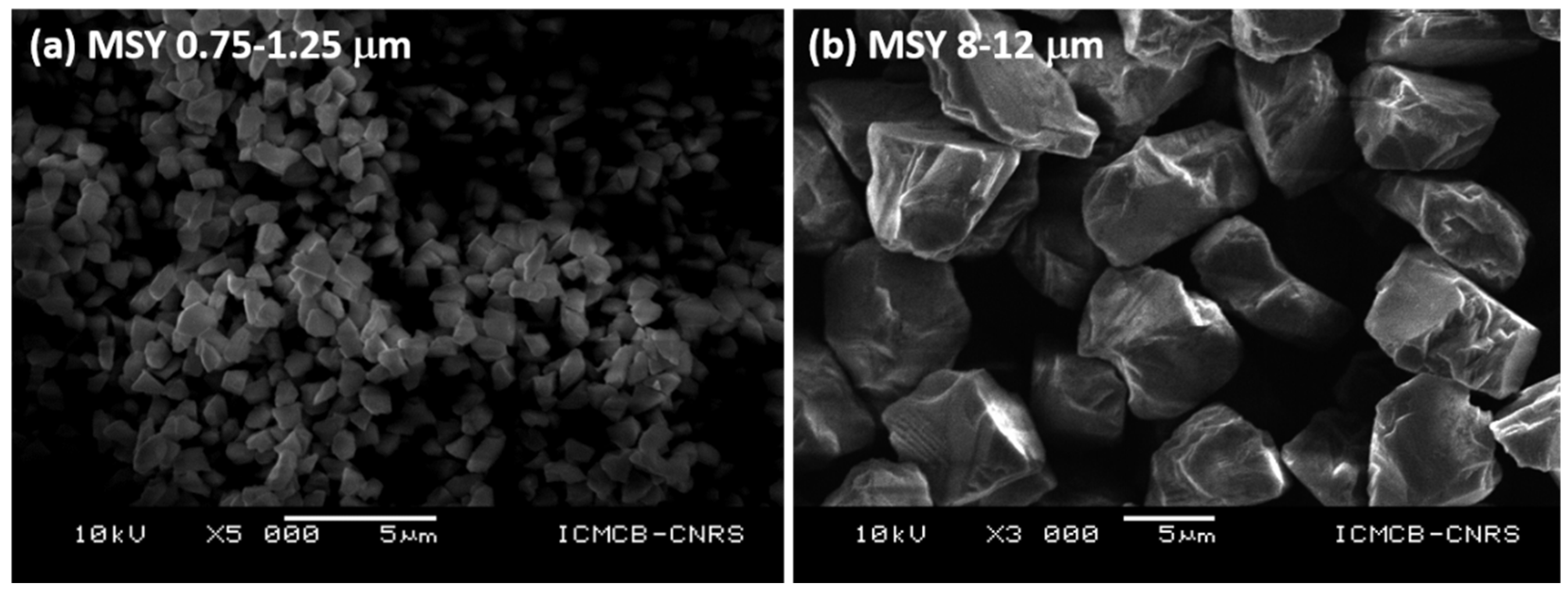
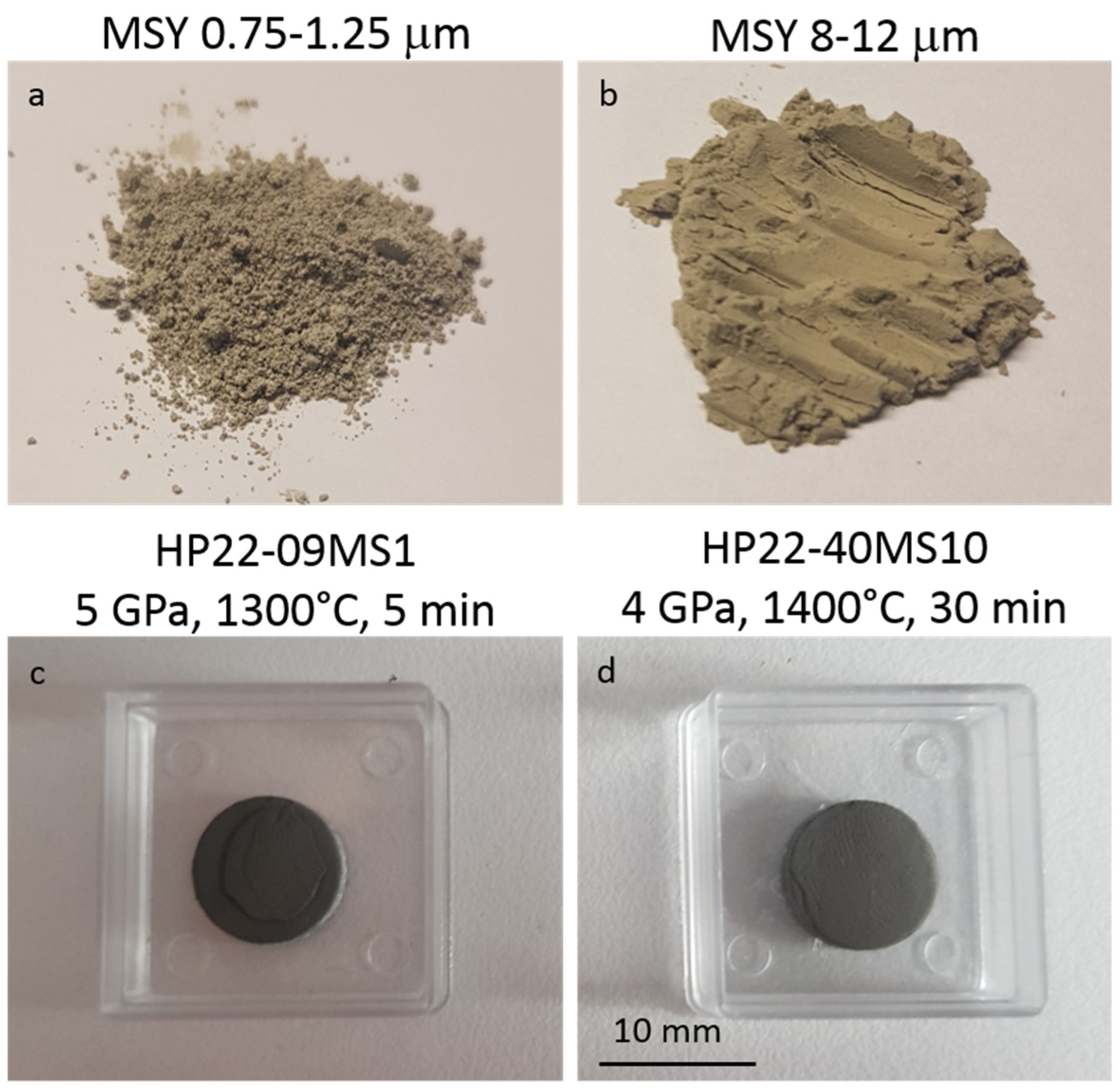
| Run # | Grain Size (μm) | Quantity (g) | P (GPa) | T (°C) | Dwell Time (min) | 1 Density (g cm−3) | XRD | Grain Boundary Formation |
|---|---|---|---|---|---|---|---|---|
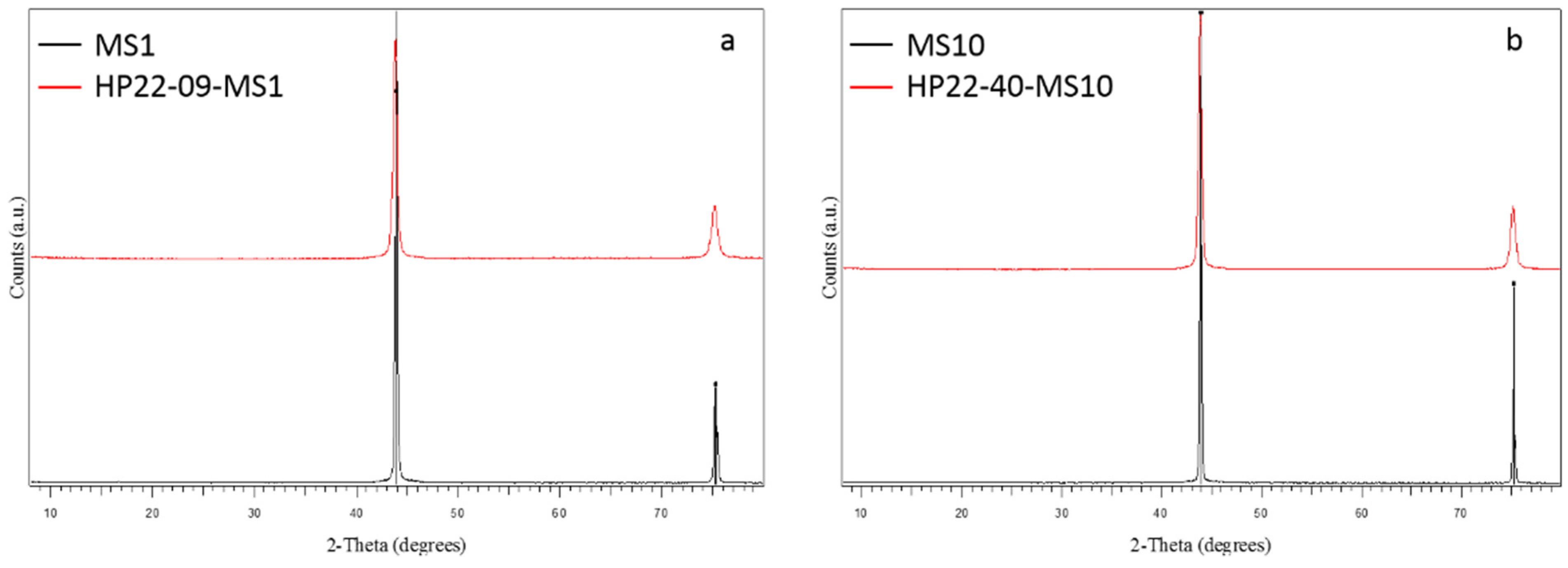
| HP22-09-MS1 | 0.75–1.25 | 0.5 | 5 | 1300 | 5 | 3.05 | c-C | +++ |
| HP22-40-MS10 | 8–12 | 0.5 | 4 | 1400 | 30 | 2.80 | c-C | ++ |
Publisher’s Note: MDPI stays neutral with regard to jurisdictional claims in published maps and institutional affiliations. |
© 2022 by the authors. Licensee MDPI, Basel, Switzerland. This article is an open access article distributed under the terms and conditions of the Creative Commons Attribution (CC BY) license (https://creativecommons.org/licenses/by/4.0/).
Share and Cite
Guignard, J.; Prakasam, M.; Largeteau, A. High Pressure (HP) in Spark Plasma Sintering (SPS) Processes: Application to the Polycrystalline Diamond. Materials 2022, 15, 4804. https://doi.org/10.3390/ma15144804
Guignard J, Prakasam M, Largeteau A. High Pressure (HP) in Spark Plasma Sintering (SPS) Processes: Application to the Polycrystalline Diamond. Materials. 2022; 15(14):4804. https://doi.org/10.3390/ma15144804
Chicago/Turabian StyleGuignard, Jérémy, Mythili Prakasam, and Alain Largeteau. 2022. "High Pressure (HP) in Spark Plasma Sintering (SPS) Processes: Application to the Polycrystalline Diamond" Materials 15, no. 14: 4804. https://doi.org/10.3390/ma15144804