
Effect of an Inert Gas Positive-Pressure Environment on Beryllium Melting under a Pulsed Laser


Abstract
:1. Introduction
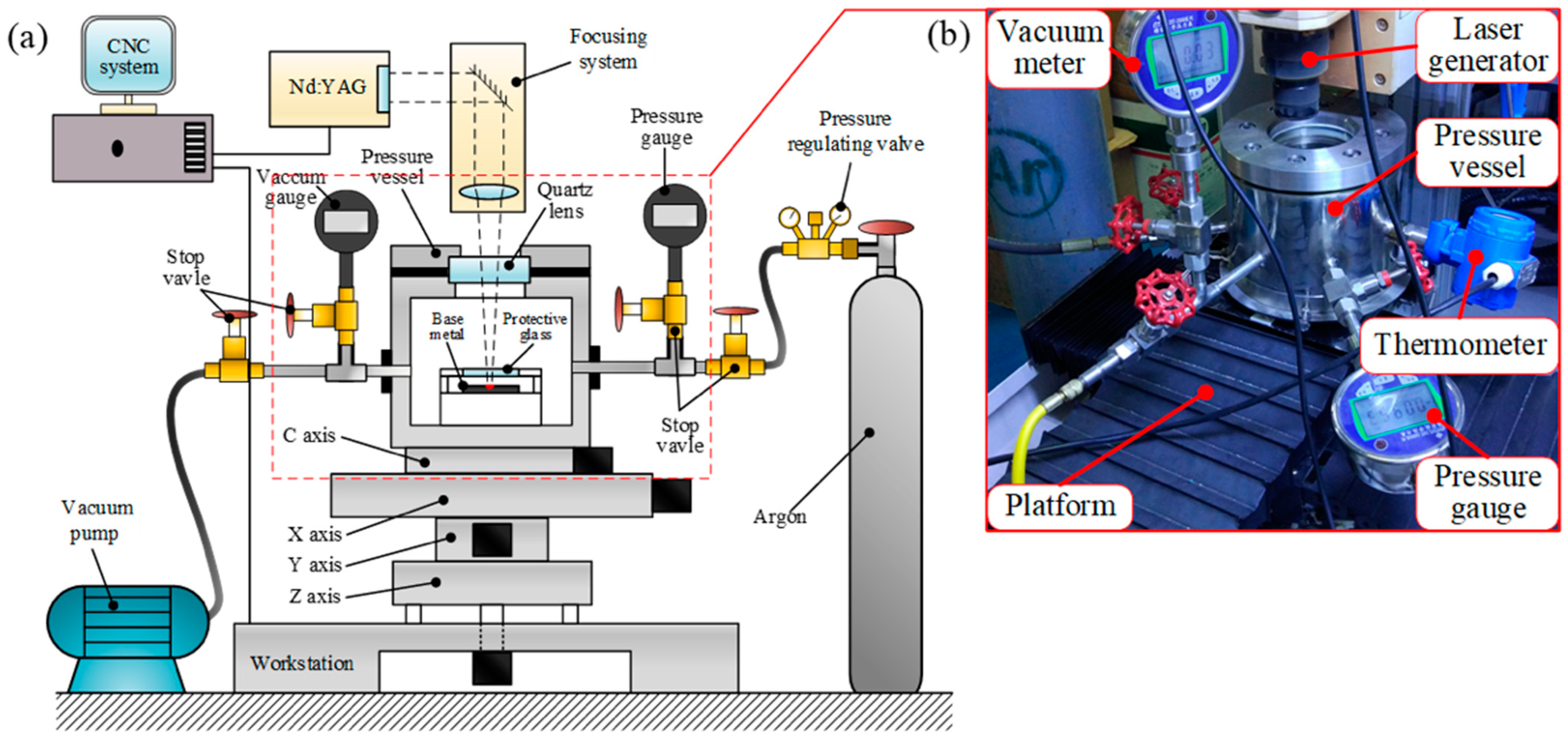
2. Experimental Setup
2.1. Workstation
2.2. Experimental Materials and Experimental Parameters
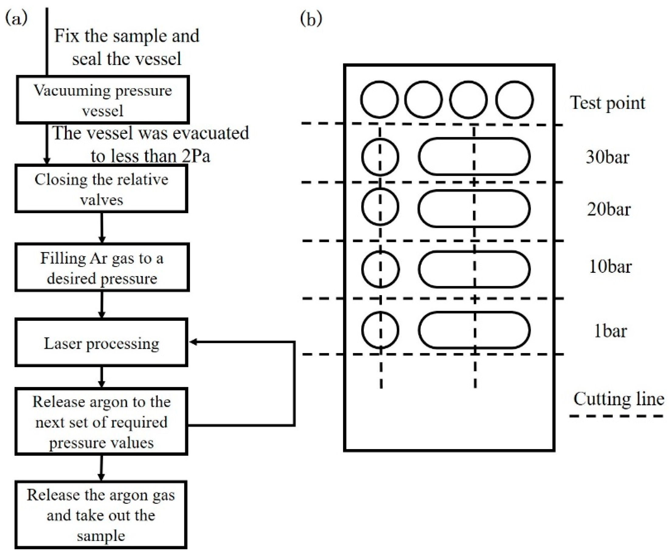
3. Experimental Program
3.1. Experimental Procedure
3.2. Observation and Test
4. Results
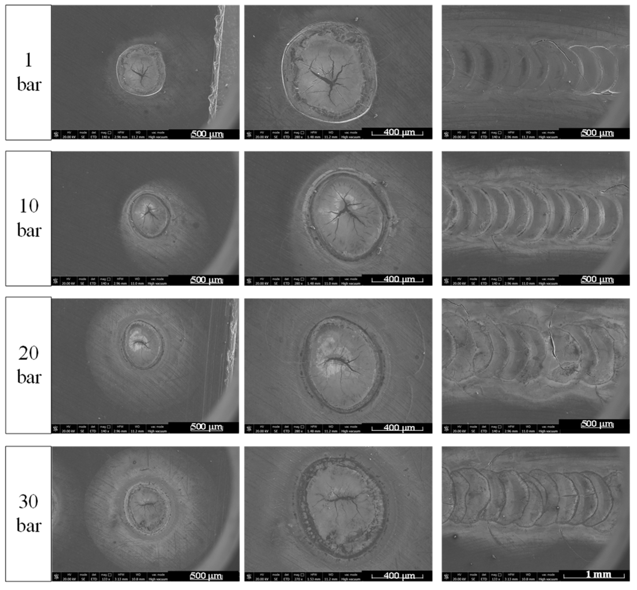
4.1. Surface Appearance of Molten Pools
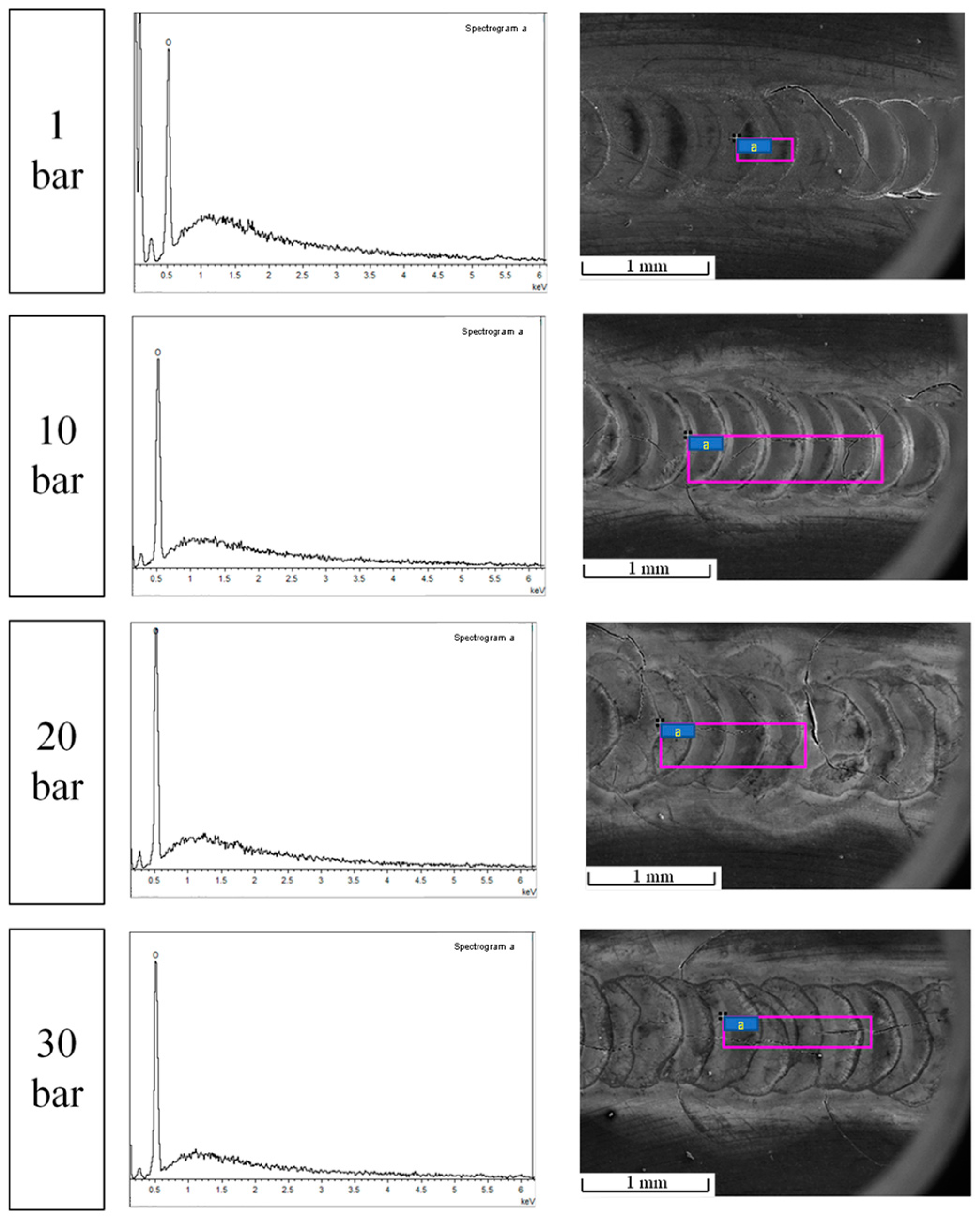
4.2. Surface SEM/EDS Test
4.3. Cross-Section Shape and Microstructure of Solidification Pools
5. Discussion
Evolution of the Laser Melting Process
6. Conclusions
- Although the laser absorptivity of pure beryllium is relatively low, it can absorb the laser and form a molten pool. The contour area of the upper surface of the molten pool is approximately 80% of that of 304 stainless steel under the same energy input;
- Beryllium is highly reactive. Under vacuum or low pressure, owing to the violent eruption of metal vapor, beryllium reacts with the residual oxygen in the environment to form oxides and falls on the surface and around the molten pool. When the ambient pressure is higher than 10 bar, oxidation is eliminated. A high-pressure environment and low energy density can eliminate oxidation;
- Beryllium cracks easily during laser processing. As pressure increases, the surface cracking of beryllium changes from “divergent” to “shrinkage”, which demonstrates that the high-pressure environment has the tendency to eliminate the cracks in the process of beryllium laser processing;
- The ambient pressure affects the laser-processing melting of beryllium. It is easy to form a greater penetration at low pressure, exhibiting the trend of “small holes”. When the pressure increases, the formation of “small holes” is inhibited. When the ambient pressure reaches 30 bar, the generation of “small holes” is completely suppressed, and the width of the molten pool increases to the widest. For the direct deposition process, a wide and shallow molten pool is more conducive to the stability of the deposition process. Therefore, a suitable barotropic environment can have a positive effect.
Author Contributions
Funding
Institutional Review Board Statement
Informed Consent Statement
Data Availability Statement
Conflicts of Interest
References
- Sun, S. Ideal material for inertial instrument structure—Beryllium. Aerosp. China 1992, 1, 46–49. Available online: https://kns.cnki.net/kcms/detail/detail.aspx?FileName=ZGHT199201017&DbNam-e=CJFQ1992 (accessed on 7 May 2020).
- Xu, D.; Qing, G.; Li, F.; Wang, Z.; Zhong, J.; He, J.; He, L. Advance in beryllium and beryllium-containing materials. Chin. J. Nonferrous Met. 2014, 24, 1212–1223. [Google Scholar] [CrossRef]
- Tolias, P. Analytical expressions for thermophysical properties of solid and liquid beryllium relevant for fusion applications. Nucl. Mater. Energy 2022, 31, 101195. [Google Scholar] [CrossRef]
- Federici, G.; Doerner, R.; Lorenzetto, P.; Barabash, V. Beryllium as a Plasma-Facing Material for Near-Term Fusion Devices. Compr. Nucl. Mater. 2012, 4, 621–666. [Google Scholar] [CrossRef]
- Zhang, Y.; Qing, Y.; Wu, D.; Xie, Z. Properties and applications of beryllium and beryllium-containing materials. Trans. China Weld. Inst. 2001, 22, 92–96. Available online: https://kns.cnki.net/kcms/detail/detail.aspx?FileName=HJXB200106032&DbName=CJFQ2001 (accessed on 8 July 2021).
- Zheng, L.; Wang, X.; Yue, L.; Huang, J.; Zhong, J. Progress in the Application of Rare Light Metal Beryllium and Its Alloys. Chin. J. Rare Met. 2021, 45, 475–483. [Google Scholar] [CrossRef]
- Zhong, J.; Li, Z.; Wang, Z.; Wang, D.; Li, F.; Li, J.; Zhang, J. Progress in research and application of beryllium materials used in inertial guidance instrument. Powder Metall. Ind. 2018, 28, 1–6. [Google Scholar] [CrossRef]
- Haws, W.J. New trends in powder processing beryllium-containing alloys. JOM 2000, 52, 35–37. [Google Scholar] [CrossRef]
- Saxton, D.; Parsonage, T.B. Advances in near net shape beryllium manufacturing technologies. Opt. Des. Mater. Fabr. Maint. 2000, 4003, 80–90. [Google Scholar] [CrossRef]
- Lin, X.; Huang, W. High Performance Metal Additive Manufacturing Technology Applied in Aviation Field. Mater. China 2015, 34, 684–688. [Google Scholar]
- Ahn, D.G. Direct metal additive manufacturing processes and their sustainable applications for green technology: A review. Int. J. Precis. Eng. Manuf.–Green Technol. 2016, 3, 381–395. [Google Scholar] [CrossRef]
- DebRoy, T.; Wei, H.L.; Zuback, J.S.; Mukherjee, T.; Elmer, J.W.; Milewski, J.O.; Beese, A.M.; Wilson-Heid, A.; De, A.; Zhang, W. Additive manufacturing of metallic components–Process, structure and properties. Prog. Mater. Sci. 2018, 92, 112–224. [Google Scholar] [CrossRef]
- Zhang, D.; Sun, S.; Qiu, D.; Gibson, M.A.; Dargusch, M.S.; Brandt, M.; Qian, M.; Easton, M. Metal Alloys for Fusion-Based Additive Manufacturing. Adv. Eng. Mater. 2018, 20, 1700952. [Google Scholar] [CrossRef]
- Liu, Y.; Han, P.; Hu, S.; Cao, Y. Development of Laser Additive Manufacturing With Metallic Materials and Its Application in Aviation Engines. Aeronaut. Manuf. Technol. 2014, 10, 62–67. [Google Scholar] [CrossRef]
- Qi, M.; Li, X.; Xu, L. Analysis on the application of additive manufacturing technology in the development of weapons and equipment in the field of national defense abroad. Def. Manuf. Technol. 2018, 3, 13–19. Available online: https://kns.cnki.net/kcms/detail/detail.aspx?FileName=GFZZ201801004&DbName=CJFQ2018 (accessed on 24 August 2021).
- Lin, X.; Huang, W. Laser additive manufacturing of high-performance metal components. Sci. China Inf. Sci. 2015, 45, 1111–1126. Available online: https://kns.cnki.net/kcms/detail/detail.aspx?FileName=PZKX201509002&DbName=CJFQ2015 (accessed on 7 May 2020).
- Wang, H. Materials’ fundamental issues of laser additive manufacturing for high-performance large metallic components. Acta Aeronaut. Et Astronaut. Sin. 2014, 35, 2690–2698. [Google Scholar] [CrossRef]
- Tammas-Williams, S.; Withers, P.J.; Todd, I.; Prangnell, P.B. The Effectiveness of Hot Isostatic Pressing for Closing Porosity in Titanium Parts Manufactured by Selective Electron Beam Melting. Metall. Mater. Trans. A Phys. Metall. Mater. Sci. 2016, 47, 1939–1946. [Google Scholar] [CrossRef] [Green Version]
- Zhang, H.O.; Rui, W.; Liye, L.; Wang, G.L. HDMR technology for the aircraft metal part. Rapid Prototyp. J. 2016, 22, 857–863. [Google Scholar] [CrossRef]
- Colegrove, P.A.; Coules, H.E.; Fairman, J.; Martina, F.; Kashoob, T.; Mamash, H.; Cozzolino, L.D. Microstructure and residual stress improvement in wire and arc additively manufactured parts through high-pressure rolling. J. Mater. Process. Technol. 2013, 213, 1782–1791. [Google Scholar] [CrossRef]
- Colegrove, P.A.; Martina, F.; Roy, M.J.; Szost, B.A.; Terzi, S.; Williams, S.W.; Withers, P.J.; Jarvis, D. High pressure interpass rolling of Wire + Arc additively manufactured titanium components. Adv. Mater. Res. 2014, 996, 694–700. [Google Scholar] [CrossRef] [Green Version]
- Thorén, E.; Ratynskaia, S.; Tolias, P.; Pitts, R.A. The MEMOS-U code description of macroscopic melt dynamics in fusion devices. Plasma Phys. Control. Fusion 2021, 63, 035021. [Google Scholar] [CrossRef]
- Su, J.; Zhang, Z.; Xiao, M.; Ye, Z.; Yang, Y. Effects of ambient pressure on single-pulse laser processing of austenite stainless steel. J. Mater. Processing Technol. 2019, 263, 59–72. [Google Scholar] [CrossRef]
- He, J.; Li, S.; Xie, Z.; Jiang, Y. Welding procure and microstructure of beryllium by las-er keyhole welding. Aerosp. Mater. Technol. 2008, 4, 44–47. Available online: https://kns.cnki.net/kcms/detail/detail.aspx?FileName=YHCG200804012&DbName=CJFQ2008 (accessed on 8 July 2021).
- Luo, Y.; Tang, X.; Lu, F.; Chen, Q.; Cui, H. Effect of subatmospheric pressure on plasma plu-me in fiber laser welding. J. Mater. Processing Technol. 2015, 215, 219–224. [Google Scholar] [CrossRef]
- Kim, J.; Oh, S.; Son, M.; Ki, H. A study of keyhole behavior and weldability in zero-gap laser welding of zinc-coated steel sheets at subatmospheric pressures. J. Mater. Processing Technol. 2017, 249, 135–148. [Google Scholar] [CrossRef]
- Shannon, G.J.; McNaught, W.; Deans, W.F.; Watson, J. High power laser welding in hyperbaric gas and water environments. J. Laser Appl. 1997, 9, 129–136. [Google Scholar] [CrossRef]
- Shannon, G.J.; Watson, J.; Deans, W.F. Laser welding in a high pressure gas environment. Opt. Laser Technol. 1995, 27, 397–398. [Google Scholar] [CrossRef]
- Li, S.; Jiang, Y.; Zhang, Y.; Xie, Z.; Wu, D.; Zhang, Z.; Zhang, T.; Qing, Z. Influencing factors of critical power density for beryllium laser welding. In Annual Report of China Academy of Engineering Physics; Sichuan Science and Technology Press: Chengdu, China, 2002; pp. 537–538. Available online: https://kns.cnki.net/kcms/detail/detail.aspx?FileName=GCWL200200001459&DbName=CPFD2006 (accessed on 8 July 2021).
- Qiu, Z.; Xiao, D.; Chen, X.; Lang, D. Mechanical Properties of Be at Different Temperatures. Chin. J. Rare Met. 2015, 39, 16–22. [Google Scholar] [CrossRef]


| Parameters | Single-Pulse Energy | Current of Laser Power Supply | Pulse Width | Frequency | Scanning Speed | Defocusing Amount |
|---|---|---|---|---|---|---|
| Value | 55 J | 240 A | 4 ms | 3 Hz | 25 mm/min | −5 mm |
| Position in the Molten Pool | Illustrations | Observation Methods |
|---|---|---|
| Surface |  | LSCM SEM/EDS |
| Cross-section | 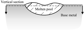 | LSCM |
Publisher’s Note: MDPI stays neutral with regard to jurisdictional claims in published maps and institutional affiliations. |
© 2022 by the authors. Licensee MDPI, Basel, Switzerland. This article is an open access article distributed under the terms and conditions of the Creative Commons Attribution (CC BY) license (https://creativecommons.org/licenses/by/4.0/).
Share and Cite
Sang, Y.; Xiao, M.; Zhang, Z.; Su, J. Effect of an Inert Gas Positive-Pressure Environment on Beryllium Melting under a Pulsed Laser. Materials 2022, 15, 4916. https://doi.org/10.3390/ma15144916
Sang Y, Xiao M, Zhang Z, Su J. Effect of an Inert Gas Positive-Pressure Environment on Beryllium Melting under a Pulsed Laser. Materials. 2022; 15(14):4916. https://doi.org/10.3390/ma15144916
Chicago/Turabian StyleSang, Yuxin, Muzheng Xiao, Zhijing Zhang, and Jiangzhou Su. 2022. "Effect of an Inert Gas Positive-Pressure Environment on Beryllium Melting under a Pulsed Laser" Materials 15, no. 14: 4916. https://doi.org/10.3390/ma15144916
APA StyleSang, Y., Xiao, M., Zhang, Z., & Su, J. (2022). Effect of an Inert Gas Positive-Pressure Environment on Beryllium Melting under a Pulsed Laser. Materials, 15(14), 4916. https://doi.org/10.3390/ma15144916