Article

Processing and Microstructure of As-Cast Ti-45Al-2W-xC Alloys

1
Faculty of Materials Science and Technology, VSB—Technical University of Ostrava, 70800 Ostrava, Czech Republic
2
Institute of Materials and Machine Mechanics, Slovak Academy of Sciences, Dubravska Cesta 9, 84513 Bratislava, Slovakia
*
Author to whom correspondence should be addressed.
Materials 2022, 15(14), 5049; https://doi.org/10.3390/ma15145049
Submission received: 29 June 2022 / Revised: 11 July 2022 / Accepted: 18 July 2022 / Published: 20 July 2022

Abstract

:
The metallurgical preparation and microstructure of as-cast Ti-45Al-2W-xC (in at.%) alloys were investigated. Five alloys with carbon content ranging from 0.38 to 1.96 at.% were prepared by vacuum induction melting (VIM) in graphite crucibles, followed by centrifugal casting into graphite moulds. A master 15W-85Al (at.%) alloy with a relatively low melting point and TiC powder were used to facilitate fast dissolution of W during VIM and to achieve the designed content of C in the as-cast alloys, respectively. The increase in the content of C affects the solidification path of the studied alloys. Differential thermal analysis (DTA) and microstructural observations show that the alloys with carbon content up to 0.75 at.% solidify with β primary phase and their dendritic as-cast microstructure consists of the α2(Ti3Al) + γ(TiAl) lamellar regions, retained B2 phase enriched by W and single γ phase formed in the interdendritic region. The increase in the content of C above 0.75 at.% leads to the formation of primary lathe-shaped Ti2AlC carbides, which act as effective heterogeneous nucleation sites of β dendrites during the solidification and grain refinement of the alloys with 1.15 and 1.96 at.% C. The increase in the content of C leads to an increase in Vickers hardness and elastic modulus in the alloys containing 1.96 at.% C.

1. Introduction

Among various high-temperature materials, lightweight TiAl-based alloys are of great interest due to their low density and a good combination of mechanical properties at elevated temperatures [1,2,3,4,5,6]. These materials can fulfil requirements for some structural applications in the automotive, energy, and aerospace industries. However, their low room temperature ductility, difficult processing, and insufficient creep resistance at temperatures higher than 750 °C limit their wider industrial use [7]. Refractory metals such as W with a low diffusivity in TiAl alloys can significantly increase mechanical properties and corrosion resistance at elevated temperatures [7]. Alloying with W reduces dislocation mobility and increases the thermal stability of lamellar microstructure, which leads to an increase in creep resistance [8,9,10,11,12,13]. The positive influence of carbon on the creep strength of TiAl-based alloys has been published by several authors [14,15,16,17]. The carbide precipitation is greatly influenced by carbon solubility limit, which varies with Al content and the content of other alloying elements [16,18,19]. The effect of carbon content on creep has been investigated mainly in Nb-containing TiAl-based alloys. It has been shown that the increase in creep strength of these alloys can be attributed to solid solution and precipitation strengthening mechanisms. The carbides forming in TiAl-based alloys belong to the cubic perovskite Ti3AlC (P-type) phase with needle-like morphology or to the hexagonal Ti2AlC (H-type) phase with plate-like morphology [20,21,22]. Above the carbon solubility limit in TiAl-based alloys, the formation of primary Ti2AlC carbides have been reported, for which chemistry, size, and shape depend on the alloying additions, carbon content, and processing parameters [23,24,25,26,27,28,29].
Vacuum induction melting (VIM) followed by precise gravity or centrifugal casting is identified to be one of the most cost-effective technologies for the production of complex-shaped components from TiAl-based alloys [30,31,32,33,34]. In recent years, additive manufacturing (AM) has been intensively explored as a new method for the fabrication of complex-shaped components from TiAl-based alloys [35,36,37]. The main factor limiting a wider application of additive manufacturing for the production of TiAl-based alloys and components is the availability and high price of TiAl powders with the required chemical composition [2]. Both VIM combined with precise casting and AM depend on the availability of TiAl ingots with the required chemical composition and quality. Up to now, several techniques such as vacuum arc remelting (VAR), plasma arc melting (PAM), electron beam melting (EBM), and VIM have been developed for the production of TiAl ingots [38,39]. Several different types of oxide ceramics have been tested for VIM of TiAl alloys, e.g., CaO, Al2O3, Y2O3, BaZrO3, and BaZrO3/Y2O3. It was found that the type of oxide ceramic material affects significantly the oxygen content and amount of non-metallic inclusions in the as-cast alloys [40,41,42,43,44,45,46]. VIM of TiAl-based alloys in graphite crucibles leads to an increase in the content of C, which can be beneficial for the improvement of high temperature creep resistance [17,47]. It has been shown that the content of C can be controlled by an appropriate selection and optimisation of processing parameters, such as heating rate, melt temperature, holding time at the melt temperature, arrangement of the charge in a graphite crucible, chemical composition of master alloys, and vacuum pressure [26,47,48]. Water-cooled copper crucibles have been applied for VIM or VAR to minimize contamination of TiAl ingots. However, heat losses due to significant heat dissipation due to cooling of the copper crucible significantly reduce energy efficiency of TiAl ingot production [49,50].
Kamyshnykova et al. [51] have reported that the mechanical properties of heat-treated TiAl–W based alloys can be improved by carbon additions ranging from 0.4 to 2 at.%. The Ti–45Al-2W-xC (at.%) alloys with fully lamellar microstructure and the addition of carbon close to its solubility limit have shown superior creep resistance compared to that of carbon-free TiAl–W and reference TiAl-based alloys at a temperature of 800 °C. A significant improvement in high-temperature creep resistance of Ti-45Al-2W-xC (at.%) alloys has been attributed to the solid solution strengthening effect of carbon, better thermal stability of α2 + γ lamellar microstructure, stabilisation of α2 phase with carbon, and precipitation strengthening by Ti3AlC and B2 particles forming during decomposition of the α2 phase [51]. Despite previous studies on the metallurgical processing of TiAl ingots by VIM in graphite crucibles [14,26,44,47,51,52] and the properties of W containing TiAl-based alloys [10,11,12,13], no information has been published on the effect of C on the microstructure of as-cast TiAl-W alloys.
This study aims to investigate the metallurgical processing route consisting of VIM in graphite crucibles followed by centrifugal casting into graphite moulds for the preparation of ingots with nominal composition Ti-45Al-2W-xC (at.%), where content of carbon ranges from x = 0.4 to 2 at.%. The effect of the content of C on the microstructure, segregation behaviour of alloying elements, phase transformations, hardness, and elastic modulus of five as-cast alloys is reported and discussed.

2. Materials and Methods

VIM was used for the alloy preparation. Scanning electron microscopy (SEM), thermo-evolution methods for determination of interstitial elements, X-ray difraction analysis (XRD), and energy dispersive spectroscopy (EDS) were used to investigate the chemical composition, phase identification, microstructure, and segregation. Differential thermal analysis (DTA) was used to determine the phase transition temperatures and hardness testing experiments were used for mechanical testing. Five independent measurements for each type of alloy were applied, with the exception of segregation profiles and DTA.
The studied TiAl-based alloys with designed nominal composition Ti-45Al-2W-(0.4–2)C (at.%) were prepared by VIM in isostatically pressed graphite crucibles and centrifugally cast into a graphite mould using a Supercast device (Linn High Therm GmbH, Eschenfelden, Germany). Pure Ti (grade 2) and Al (99.99%) and pieces of 15W-85Al (at.%) master alloy (see Figure 1) were used as the charge. The master alloy, composed of WAl4 and WAl12 phases distributed in the Al matrix, had a relatively low melting point of 1350 °C compared to that of pure W, which was used to facilitate the fast dissolution of W during VIM [53]. Isostatically pressed graphite crucibles ϕ65/135 mm (diameter/length) were applied to melt a charge with a weight of 410 g. An alumina-based crucible connected with a graphite mould was used to protect the graphite melting crucible. Before melting, the vacuum induction furnace was evacuated to a pressure of 20 Pa and rinsed with high purity Ar (99.9995%) three times. After increasing the vacuum pressure to 1.5 × 10⁴ Pa by a partial filling of the vacuum chamber with high purity argon, the charge was heated to a melt temperature of 1700 °C and held at this temperature for 30 s. The temperature of the melt was measured by a pyrometer. Different contents of carbon in the alloys were achieved by the addition of TiC powder into the charge, as shown in Figure 2. Figure 3 shows the typical example of an as-cast ingot with a diameter of 20 mm and length of 200 mm length in which the conical feeding head was removed by cutting using a diamond wheel.
Typical wet grinding using 60–2000 sandpapers (grains/cm−2) was used for metallographic sample preparation. Diamond suspensions (from 6 to 0.3 µm) were used for polishing the grounded surfaces of the samples. The microstructure evaluation was carried out with light microscopy (LM) and SEM using an Olympus GX 51 microscope (Olympus Corporation, Shinjuku, Japan) and a Quanta 450 FEG microscope (FEI Company, Fremont, CA, USA), respectively. Secondary electron (SE) and back-scattered electron (BSE) modes have been used for SEM. EDS was applied to determine the chemical composition. Calibration of EDS with the Ti2AlC standard was carried out for the measurements of the composition of coarse carbide particles. A Bruker D8 DISCOVER diffractometer (Bruker, Billerica, MA, USA) was used for XRD analyses. X-ray tube with a rotating Cu anode operating at 12 kW and parallel beam geometry with a parabolic Goebel mirror in the primary beam were used during XRD measurements. The O, N, and H contents in the alloys were specified by the thermo-evolution method with LECO ONH 836 instrument (LECO, Geleen, Netherland). The average content of C was detected by the thermo-evolution method on an ELTRA CS 2000 instrument (ELTRA, Haan, Germany). Differential thermal analysis (DTA), was performed with Setaram SETSYS 18TM experimental analyser (SETARAM Instrumentation, Caluire, France). Electroerosive cutting (EDM) was used to prepare DTA samples (3 × 3 × 3 mm) from the as-cast ingots. The surface of the samples was subsequently modified by wet grinding (600 grains/cm−2). Corundum crucibles were used for DTA experiments. Triple flushing with high purity Ar (99.99995) was applied. The heating and cooling cycles of DTA were carried out at a rate of 15 °C/min under Ar atmosphere. The DTA cooling curves were analysed to determine the phase transformation temperatures. Melting points of pure Pd and Ag (99.9995) were used for calibrations of DTA apparatus. The weights of the individual samples and the cooling rates were taken into account for the correction of the phase transformation temperatures.
Hardness was measured by Zwick/Roell ZHU 2.5 equipment (ZwickRoell GmbH, Ulm, Deutschland). Instrumented Martens hardness measurements (98.1 N applied load, 1 s time, 15 N/s loading rate) were carried out. An applied load of 98.1 N and a time of load application of 10 s were used for Vickers hardness measurements.

3. Results and Discussion

3.1. Chemical Composition and Microstructure of the As-Cast Ingots

The studied alloys with nominal compositions Ti-45Al-2W-xC, where x is 0.4, 0.5, 0.8, 1.2, and 2.0 (in at.%) and designated as C4, C5, C8, C12, and C20, respectively, are summarized in Table 1. As can be seen in the table, the measured chemical compositions of the as-cast ingots, including the content of C, are close to the designed nominal ones. The measured high content of nitrogen up to 500 wt.ppm and oxygen up to 1200 wt.ppm in the ingots results from a lower purity of Ti containing up to 300 wt.ppm of N and up to 2500 wt.ppm of O. The present results indicate that VIM in graphite crucibles, followed by casting into graphite moulds, can be applied for the processing of TiAl-based alloys containing strong carbide forming elements such as Ti and W with the controlled carbon content and reproducible chemical composition. The applicability of VIM in graphite crucibles for the cost-effective processing of carbon-containing TiAl-based alloys with a controlled content of C and reproducible chemical compositions has been reported by several authors [14,25,47,54].
Figure 4 shows the typical microstructure of the as-cast C4, C5, C8, C12, and C20 alloys. The microstructure of the as-cast alloys is dendritic, as shown in Figure 4a–e. Within the dendrites, a bright network of the B2 phase results from the solid-state phase transformation of the β phase to the α and reordering of β to B2 at lower temperatures [55,56,57]. The α phase transforms into a fine lamellar α2 + γ microstructure and a low amount of a single γ phase can be preserved in the interdendritic region. This type of microstructure is typical for as-cast TiAl-based alloys, containing additions of Nb, Ta, Mo, and W [58,59]. However, the microstructure of the as-cast alloys shows significant changes with increasing carbon content. Figure 5 shows the typical XRD diffraction patterns of the C4 and C20 alloys, indicating the presence of four phases: γ, α2, B2, and H-Ti2AlC (in C20 alloy). Besides the C20 alloy, the formation of plate-like Ti2AlC particles is also identified in the C12 alloy, as shown in Figure 4d. Figure 6 shows the microstructure in the interdendritic region of the C4 and C20 alloys. In both alloys, the interdendritic region is composed mainly of the γ phase and a small amount of lamellar α2 phase, as shown in Figure 6a,b. Table 2 summarises the measured chemical composition of the individual phases and microstructural regions in the as-cast alloys. The individual phases and regions in the C4, C5, C8, C12, and C20 alloys do not show significant differences in the content of Ti, Al, and W. Figure 7 shows the dependence of the volume fraction of individual phases and microstructural regions on carbon content. The volume fraction of the B2 phase decreases from 10 vol.% to 4 vol.%, with increasing carbon content from 0.38 to 1.96 at.%. The same tendency is also observed for the volume fraction of the interdendritic α2 + γ region, which decreases from 8.8 vol.% to 6 vol.%. The volume fraction of dendritic lamellar α2 + γ regions increases with increasing carbon content from 81 vol.% to 85 vol.% with increasing carbon content from 0.38 to 1.96 at.%. It should be noted that the carbon content affects interlamellar α22 spacing, which decreases with increasing carbon content up to a solubility limit of carbon in TiAl-based alloys [54]. The volume fraction of plate-like primary Ti2AlC particles increases from 2.9 vol.% to 5.4 vol.% with increasing carbon content from 1.15 to 1.96 at.%. As shown by Lapin et al. [23], the volume fraction of primary Ti2AlC particles depends on the carbon content and increases linearly with increasing carbon in Ti-44.5Al-8Nb-0.8Mo-0.1B-xC (at.%) alloys.

3.2. Segregation Behaviour of Alloying Elements

The segregation behaviour of the alloying elements and the chemical homogeneity of the as-cast ingots was assessed by the EDS line analysis with a step of 40 µm (500 points). Figure 8 shows the measured variations in the alloying elements with the illustration of the positions of the analyzed points at the transversal sections of the as-cast C4 and C20 ingots. Significant dendritic segregation can be observed in the sample C4 at first glance. The contents of Ti and Al in the C4 ingot vary from 50 to 53 at.% and from 44 to 47 at.%, respectively, as seen in Figure 8a,b. The most significant segregation is associated with a decrease in the content of Ti to 46 at.%. For Al, the most pronounced segregation is associated with the increase in the content of Al to 54 at.% in several analysed points, which is associated with the presence of an interdendritic single γ phase in the microstructure. The formation of the interdendritic γ phase in the as-cast alloys can be explained by the microsegregation behaviour of the alloying elements. Aluminium characterized by the partition coefficient of kAl = 0.9 segregates preferentially into interdendritic liquid during solidification [60,61]. Locally, the last liquid enriched in Al solidifies through the formation of a single γ phase, as seen in Figure 4a–d [4,54]. It is important to note that O (kO = 1.29) behaves similarly to Ti (kTi = 1.14) or W and segregates into the dendrites [60,61]. The EDS line analysis of the C20 ingot shows more pronounced segregation, with the opposite tendency associated with an increase in C content up to 26 at.% and a decrease in Al content to 25 at.%, as shown in Figure 8c,d. These segregation peaks result from the presence of the Ti2AlC particles in the microstructure. The content of W in both analyzed samples is relatively stable (1–3 at.%), and more pronounced segregation is caused by the occurrence of the B2 phase enriched in W and interdendritic γ phase enriched locally in Al. A significantly lower occurrence of larger interdendritic regions containing a single γ phase and chemically more homogenous structure of the intermetallic matrix indicates a change in solidification behaviour of the C20 alloy, which will be discussed later.

3.3. Formation of Primary Carbide Particles

Figure 9 shows the BSE micrograph and corresponding EDS mapping of elemental distribution in the reinforcing carbide particles and the surrounding matrix of the C20 alloy. An increase in Ti and C and a decrease in Al and W contents can be seen in the primary Ti2AlC particles. Although W is a strong carbide-forming element, it segregates preferentially into the remaining β/B2 phase, stabilizing this high-temperature phase forming during the solidification in the microstructure of the as-cast alloys, as seen in Figure 9. The very low solubility of W in the primary Ti2AlC (layered hexagonal MAX phase) particles has also been reported by Lapin and Kamyshnykova [25] for Ti-45Al-5Nb-2W-2C (at.%) alloy. It should be noted that the MAX phase forming elements such as Nb (Nb2AlC type of MAX phase) and Ta (Ta2AlC type of MAX phase) show high solubility, but the solubility of Mo and W is very limited in Ti2AlC phase [23,26,57].
Table 2 shows that Ti2AlC particles in the C12 and C20 alloys contain 46.7–47.2 at.% Ti, 25.4–25.6 at.% Al, 0.8 at.% W and 26.6–26.9 at.% C. The measured W content in the carbides is likely affected by the surrounding matrix. The Ti and Al contents have a ratio close to 2:1, which is typical for the Ti2AlC type of carbide and is in agreement with the publications of several authors [16,23,26,27,28,29]. Since only the alloys with 1.15 (2.9 vol.%) and 1.96 at.% C (5.4 vol.%) contain homogeneously distributed primary lathe-shaped Ti2AlC particles, the solubility limit of C in the studied Ti-45Al-2W-xC alloys is between 0.75 and 1.15 at.%, which is a higher interval than that ranging from 0.5 to 0.75 at.% reported by Gabrisch et al. [21] for Ti-45Al-5Nb-xC (at.%) alloys.
The average width and length of the primary carbides are measured to be (1.8 ± 1.1) µm and (10.6 ± 6.6) µm for the C12 alloy and (2.9 ± 1.9 µm) and (14.8 ± 10.3) µm for C20 alloy, respectively. The formation of primary Ti2AlC particles in the C12 and C20 alloys can be explained by assuming the Ti-Al-C phase diagram reported by Witusiewicz et al. [62]. The melt temperature of 1700 °C used in the present study corresponds to L(liquid) + TiC1−x phase region. During cooling, the TiC1−x particles transform to plate-like Ti2AlC according to a transformation pathway L + TiC1−x → L + Ti2AlC. The solidification continues by the formation of a secondary phase which nucleates preferentially on the plate-like Ti2AlC particles present in the melt. The plate-like Ti2AlC particles serve as heterogeneous nucleation sites during solidification, which leads to the microstructure refinement as described for similar carbon-containing TiAl-based alloys in the as-cast state by several authors [16,23,25,26,29]. The presence of the primary carbides in the C12 and C20 alloys leads to the refinement of the dendritic structure, as shown in Figure 4d,e. The refinement of the dendritic structure due to the formation of the primary Ti2AlC carbides leads to a significant reduction in the grain size. For the C4, C5, and C8 alloys, the typical columnar grains with an average length of (200 ± 70) µm and diameter of (90 ± 35) µm are observed in the microstructure. For the C12 alloy containing 2.9 vol.% of Ti2AlC, the average length and diameter of columnar grains are measured to be (70 ± 40) µm and (40 ± 10) µm, respectively. For the C20 alloy containing 5.4 vol.% of Ti2AlC, the average length and diameter of columnar grains are measured to be (45 ± 20) µm and (30 ± 15) µm, respectively, which means a reduction of grain length by up to 80% and width by up to 70% compared to samples without primary carbides.

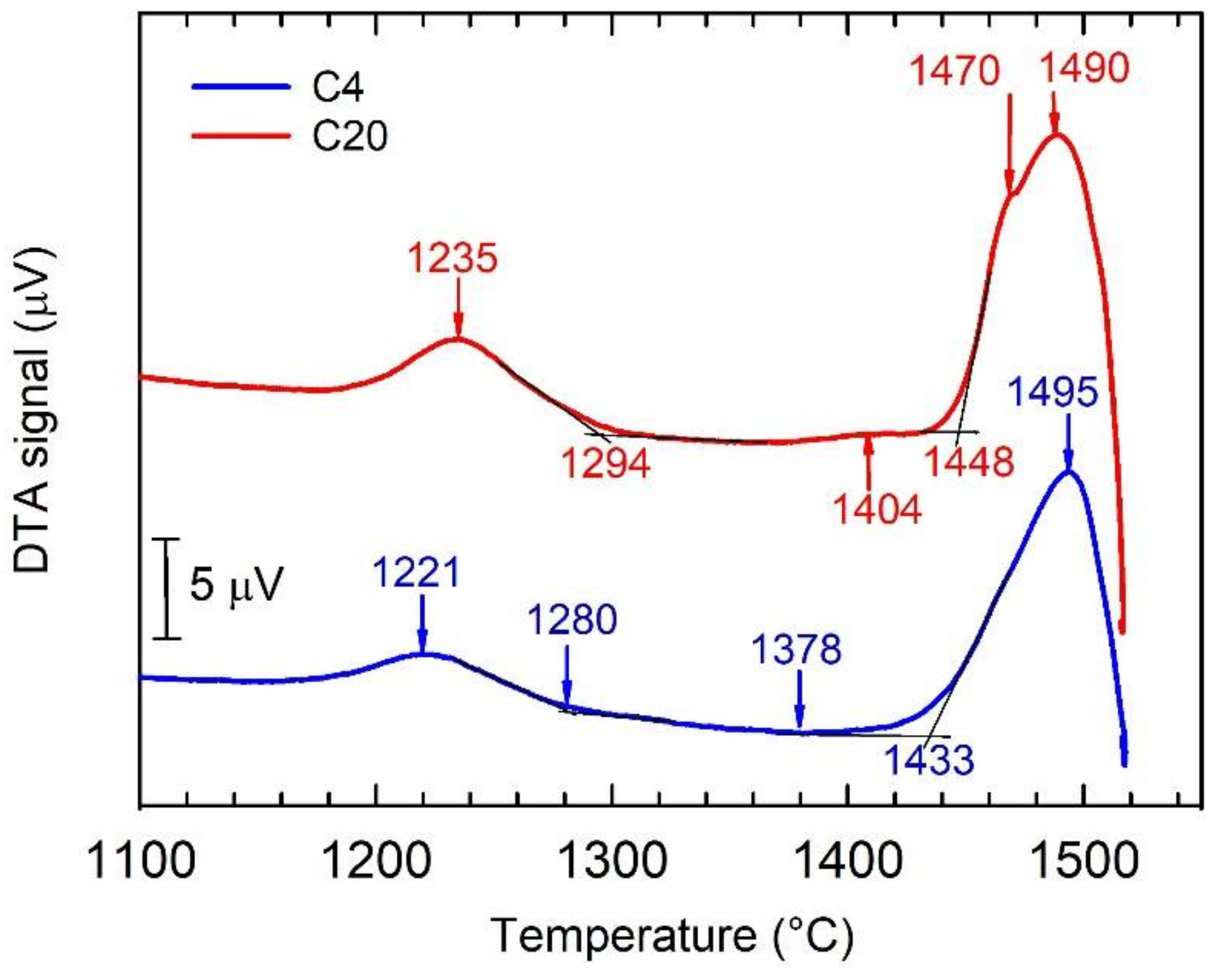
3.4. DTA Analysis of As-Cast Alloys

Figure 10 shows the DTA cooling curves of the C4 and C20 alloys. The phase transformation sequences and corresponding temperatures determined from the DTA cooling curves are summarized in Table 3. The solidification of the C4 alloy starts with the formation of the primary β phase. The β phase transforms into the α phase following the transformation sequence β → β + α in a temperature range between 1495 and 1433 °C. Figure 4a indicates that this transformation is incomplete and the network of untransformed β phase enriched by W is preserved in the as-cast microstructure. A similar type of microstructure has been reported by Ding et al. [5] for Nb-containing TiAl-based alloys solidifying through the β phase and subsequent solid-state phase transformation to α phase without a peritectic reaction/transformation. The single α phase is stable in a temperature range from 1433 to 1378 °C. Assuming the pseudo-binary Ti-Al phase diagram calculated for 2 at.% W up to a temperature of 1300 °C [63] and the fact that 0.38 at.% C does not affect significantly the phase equilibria, the formation of a single α phase region is expected. In the temperature range from 1378 to 1280 °C, the α phase transforms into a lamellar microstructure according to the transformation sequence α → α + γ. The decrease in temperature from 1280 to 1221 °C leads to an instability of the two-phase microstructure according to the transformation sequence α + γ → α + γ + β. According to the phase diagram [63], at temperatures below 1221 °C, one should expect the formation of thermodynamically stable microstructure following the transformation sequence α + γ + β → γ + B2, which has not been observed in the as-cast alloy.
In the C20 alloy, the solidification starts with the formation of primary H-Ti2AlC particles, which is followed by the solidification of the β phase according to the transformation sequence L + H → β + L + H [23]. The DTA cooling curve for the C20 alloy indicates that the β + L + H phase-field region is stable in a temperature range from 1490 to 1470 °C. At a temperature of 1470 °C, a peritectic reaction/transformation following a transformation sequence β + L + H → β + α + H leads to a full solidification of the studied C20 alloy. The presence of peritectic reaction/transformation can also be seen in Figure 4e. The peritectic α phase is formed around the β dendrites, which leads to a significant reduction in the amount of the untransformed β enriched by W and the interdendritic regions enriched by Al, as seen in Figure 4e and Figure 8b. In the temperature range from 1470 to 1448 °C, the β transforms to the α phase according to the transformation sequence β + α + H → α + H. The α + H phase is stable at temperatures between 1448 and 1404 °C. The decrease in temperature from 1404 to 1294 °C leads to an instability of the α phase according to the transformation sequence α + H → α + γ + H. In the temperature range between 1294 and 1235 °C, β phase is formed according to the transformation sequence α + γ + H → α + γ + β + H. It is expected that at temperatures below 1235 °C, a thermodynamically stable microstructure should be formed according to a transformation sequence α + γ + β + H → γ + B2 + H, which has not been achieved in the as-cast C20 alloy.

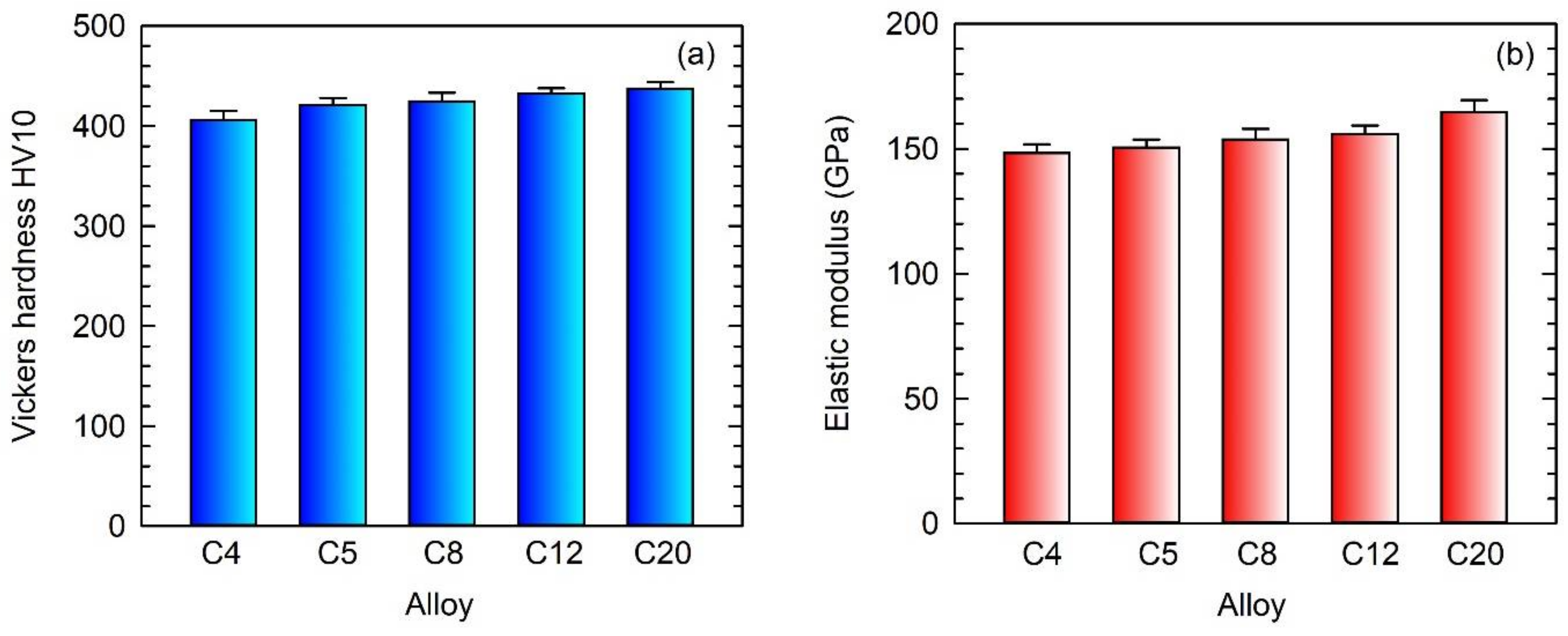
3.5. Hardness and Elastic Modulus

Figure 11 shows average values of Vickers hardness HV10 and indentation elastic modulus measurements in the as-cast C4, C5, C8, C12, and C20 alloys. It should be noted that the average values are calculated from 20 independent measurements carried out for each alloy. The increase in C content in the ingots leads to an increase in Vickers hardness HV10, as seen in Figure 11a. This increase in HV10 can be attributed to solid solution strengthening of both α2 and γ phases by carbon [19,53,64]. The solubility of carbon in the γ phase and α2 phase was determined to be 0.025–0.25 at.% [18,64] and about 1 at.% [19,65], respectively. Thus, the α2 phase can dissolve a much higher amount of carbon. However, the solubility of carbon in coexisting phases strongly depends on the chemical composition of the alloy. The increase in hardness of carbon-containing TiAl-based alloys can be attributed mainly to the solid solution strengthening effect of interstitial carbon atoms and, to a lesser extent, to the precipitation hardening with Ti3AlC and Ti2AlC carbide particles [21]. The C4 alloy shows the lowest average value of HV10, which can be attributed to the highest volume fraction of the soft interdendritic γ phase [57] in the microstructure (see Figure 6) and the lowest solid solution hardening of the coexisting phases by interstitial atoms of C. The formation of hard primary Ti2AlC particles [66] contributes to higher hardness values of the C12 and C20 alloys compared to those of C4, C5, and C8 ones. All variations in the indentation elastic modulus of the C4, C5, C8, and C12 alloys fall into the experimental error of the measurements, as seen in Figure 11b. Statistically significantly higher elastic modulus is measured in the C20 alloy. The increase in the elastic modulus to 165 GPa in the C20 alloy can be attributed to the presence of 5.4 vol.% of primary Ti2AlC particles with an elastic modulus of 234–250 GPa [25,57], which is higher than those of 176 GPa, 144 GPa, and 190 GPa reported for TiAl, Ti3Al, and B2 phases, respectively [66,67,68].

4. Conclusions

The metallurgical preparation of TiAl-based alloys with nominal composition Ti-45Al-2W-xC, where x = 0.4, 0.5, 0.8, 1.2, and 2 (at.%), and the effect of the content of C on their microstructure, segregation behaviour of alloying elements, phase transformations, hardness, and elastic modulus were studied. The following conclusions are reached:
  • The use of master 15W-85Al (at.%) alloy facilitated a fast dissolution of W in the melt and led to the metallurgical preparation of Ti-45Al-2W-(0.4–2) C alloys with designed and reproducible chemical composition, using VIM in graphite crucibles and centrifugal casting into a graphite mould.
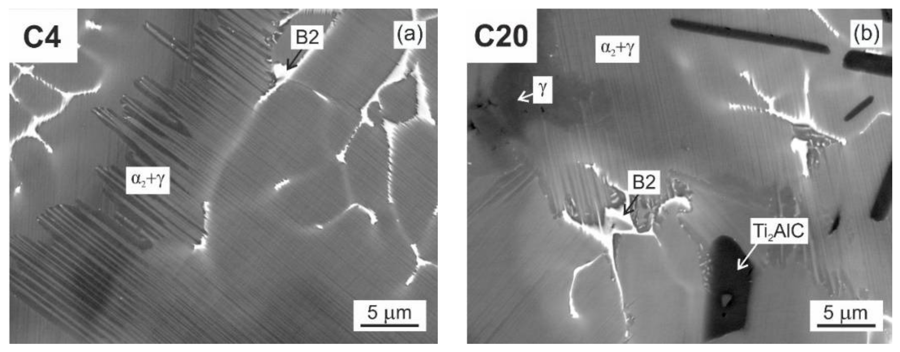
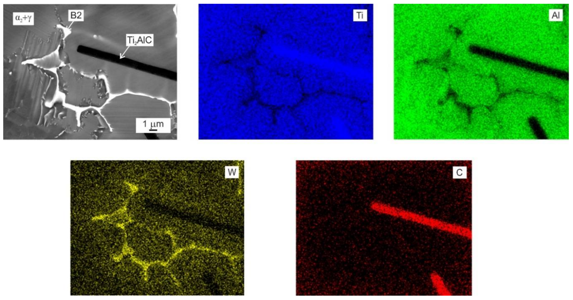
  • The microstructure of the as-cast alloys was dendritic, with high segregation of W to the dendrites. Within the dendrites, a network of B2 phase surrounded by α phase was formed, which transformed into fine lamellar α2 and γ phases during cooling. The interdendritic regions mainly contained the γ phase and a small amount of α2 phase.
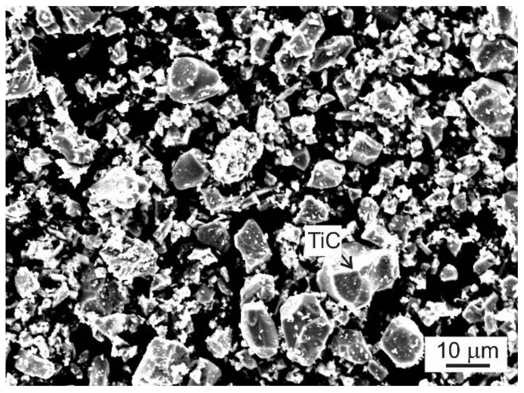
  • The alloys with additions of 1.15 and 1.96 at.% C contained coarse lathe-shaped Ti2AlC particles. The solubility limit of C in the studied alloys was determined to be between 0.75 and 1.15 at.%. The Ti2AlC carbides dissolve only a low amount of W, which segregates preferentially into β dendrites during solidification.
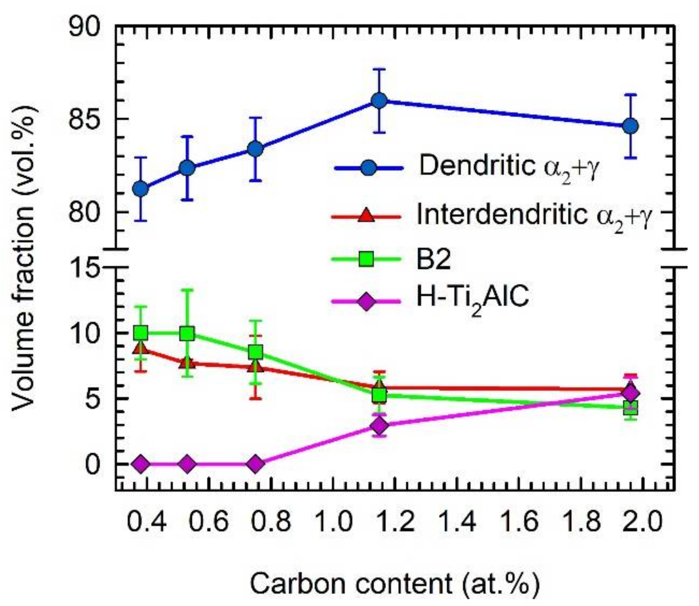
  • The Ti2AlC particles acted as heterogeneous nucleation sites during solidification, significantly refining the dendritic microstructure and reducing the grain size. The volume fraction of interdendritic α2 + γ regions and B2 phase decreased with increasing carbon content in the as-cast alloys.
  • The DTA and microstructural analysis showed that the alloys with carbon content up to 0.75 at.% solidify through β primary phase. The alloys with the carbon content above 1.15 at.% solidify through Ti2AlC primary phase. The increase in carbon content up to 1.15 at.% changed significantly on the solidification path, from L → L + β to L + H → L + β + H.
  • The Vickers hardness increases with the increasing content of C in the as-cast alloys. The elastic modulus of the C20 alloy with 5.4 vol.% of primary Ti2AlC particles is higher than that measured in the C4, C5, C8, and C12 alloys.

Author Contributions

Conceptualization, T.C. and J.L.; methodology, T.C. and J.L.; investigation, T.C., K.K., J.L., I.S., J.J. and V.K.; writing—original draft preparation, T.C.; writing—review and editing, J.L. and K.K.; visualization, T.C. and K.K. and J.J. All authors have read and agreed to the published version of the manuscript.

Funding

This work was financially supported by the Slovak Research and Development Agency under the contract APVV-20-0505, the Slovak Research and Development Agency under the contract SK-CN-21-0018 and the Slovak Grant Agency for Science under the contract VEGA 2/0018/22. This study was also conducted in association with the project Innovative and Additive Manufacturing Technology—New Technological Solutions for 3D Printing of Metals and Composite Materials (reg. no. CZ.02.1.01/0.0/0.0/17_049/0008407) financed by Structural Funds of the European Union and in association with project no. SP2022/65 “Materials based on non-ferrous metals-preparation, processes for improving their properties, area of application and the possibilities of recycling selected types of waste”.

Institutional Review Board Statement

Not applicable.

Informed Consent Statement

Not applicable.

Data Availability Statement

The data are stored by the authors of the paper, not available publically.

Conflicts of Interest

The authors declare no conflict of interest.

References

  1. Kim, Y.W. Ordered intermetallic alloys. 3. Gamma-titanium aluminides. J. Met. 1994, 46, 30–39. [Google Scholar] [CrossRef]
  2. Wu, X. Review of alloy and process development of TiAl alloys. Intermetallics 2006, 14, 1114–1122. [Google Scholar] [CrossRef]
  3. Vojtěch, D.; Popela, T.; Hamáček, J.; Kützendörfer, J. The influence of tantalum on the high temperature characteristics of lamellar gamma + alpha 2 titanium aluminide. Mater. Sci. Eng. A 2011, 528, 8557–8564. [Google Scholar] [CrossRef]
  4. Daloz, D.; Hecht, U.; Zollinger, J.; Combeau, H.; Hazotte, A.; Zaloznik, M. Micro-segregation, macrosegregation and related phase transformation in TiAl alloys. Intermetallics 2011, 19, 749–756. [Google Scholar] [CrossRef]
  5. Ding, X.; Zhang, L.; He, J.; Zhang, F.; Feng, X.; Nan, H.; Lin, J.; Kim, Y.W. As-cast microstructure characteristics dependent on solidification mode in TiAl-Nb alloys. J. Alloys Compd. 2019, 809, 151862. [Google Scholar] [CrossRef]
  6. Appel, F.; Paul, J.D.H.; Oehring, M. Gamma Titanium Aluminide Alloys: Science and Technology; Wiley-VCH Verlag & Co. KGaA: Weinheim, Germany, 2011. [Google Scholar] [CrossRef]
  7. Kim, Y.W.; Kim, S.L. Advances in gamma alloy materials–processes–application technology: Successes, dilemmas, and future. JOM 2018, 70, 553–560. [Google Scholar] [CrossRef] [Green Version]
  8. Couret, A.; Monchoux, J.P.; Cailard, D. On the high creep strength of the W containing IRIS-TiAl alloy at 850 °C. Acta Mater. 2019, 181, 331–341. [Google Scholar] [CrossRef] [Green Version]
  9. Lapin, J.; Pelachova, T. Microstructural stability of a cast Ti-45.2Al-2W-0.6Si-0.7B alloy at temperatures 973–1073 K. Intermetallics 2006, 14, 1175–1180. [Google Scholar] [CrossRef]
  10. Lapin, J.; Nazmy, M. Microstructure and creep properties of a cast intermetallic Ti-46Al-2W-0.5Si alloy for gas turbine applications. Mater. Sci. Eng. A 2004, 380, 298–307. [Google Scholar] [CrossRef]
  11. Zhou, L.Z.; Lupinc, V.; Guo, J.T. Microstructural stability of the intermetallic Ti-45Al-2W-0.5Si-0.5B in the 800–980 °C temperature range. Mater. Sci. Eng. A 2003, 354, 97–105. [Google Scholar] [CrossRef]
  12. Seo, D.Y.; Beddoes, J.; Zhao, L. Primary creep behavior of Ti-48Al-2W as a function of stress and lamellar morphology. Metall. Mater. Trans. A 2003, 34, 2177–2190. [Google Scholar] [CrossRef]
  13. Beddoes, J.; Seo, D.Y.; Saari, H. Long term creep of TiAl + W + Si with polycrystalline and columnar grain structures. Scr. Mater. 2005, 52, 745–750. [Google Scholar] [CrossRef]
  14. Szkliniarz, W.; Szkliniarz, A. Microstructure and properties of TiAl-based alloys melted in graphite crucible. Metals 2021, 11, 669. [Google Scholar] [CrossRef]
  15. Appel, F.; Paul, J.D.H.; Oehring, M.; Fröbel, U.; Lorenz, U. Creep behavior of TiAl alloys with enhanced high-temperature capability. Metall. Mater. Trans. A 2003, 34, 2149–2164. [Google Scholar] [CrossRef]
  16. Schwaighofer, E.; Rashkova, B.; Clemens, H.; Stark, A.; Mayer, S. Effect of carbon addition on solidification behavior, phase evolution and creep properties of an intermetallic β-stabilized γ-TiAl based alloy. Intermetallics 2014, 46, 173–184. [Google Scholar] [CrossRef] [Green Version]
  17. Lapin, J.; Kamyshnykova, K. Processing, microstructure and mechanical properties of in-situ Ti3Al + TiAl matrix composite reinforced with Ti2AlC particles prepared by centrifugal casting. Intermetallics 2018, 98, 34–44. [Google Scholar] [CrossRef]
  18. Scheu, C.; Sterger, E.; Schober, M.; Cha, L.; Clemens, H.; Bartels, A.; Schimansky, F.P.; Cerezo, A. High Carbon Solubility in a gamma-TiAl based Ti-45Al-5Nb-0.5C Alloy and its Effect on Hardening. Acta Mater. 2009, 57, 1504–1511. [Google Scholar] [CrossRef] [Green Version]
  19. Perdrix, F.; Trichet, M.F.; Bonnetien, J.L.; Cornet, M. Relationships between interstitial content, microstructure and mechanical properties in fully lamellar Ti–48Al alloys, with special reference to carbon. Intermetallics 2001, 9, 807–815. [Google Scholar] [CrossRef]
  20. Song, L.; Hu, X.; Wang, L.; Stark, A.; Lazurenko, D.; Lorenz, U.; Lin, J.; Pyczak, F.; Zhang, T. Microstructure evolution and enhanced creep property of a high Nb containing TiAl alloy with carbon addition. J. Alloys Compd. 2019, 807, 151649. [Google Scholar] [CrossRef]
  21. Gabrisch, H.; Stark, A.; Schimansky, F.P.; Wang, L.; Schell, N.; Lorenz, U.; Pyczak, F. Investigation of carbides in Ti-45Al-5Nb-xC alloys (0 ≤ x ≤ 1) by transmission electron microscopy and high energy-XRD. Intermetallics 2013, 33, 44–53. [Google Scholar] [CrossRef] [Green Version]
  22. Wang, L.; Oehring, M.; Lorenz, U.; Stark, A.; Pyczak, F. New insights into perovskite-Ti3AlC precipitate splitting in a Ti-45Al-5Nb-0.75C alloy by transmission electron microscopy. Intermetallics 2018, 100, 70–76. [Google Scholar] [CrossRef] [Green Version]
  23. Lapin, J.; Klimová, A.; Gabalcová, Z.; Pelachová, T.; Bajana, O.; Štamborská, M. Microstructure and mechanical properties of cast in-situ TiAl matrix composites reinforced with (Ti,Nb)2AlC particles. Mater. Des. 2017, 133, 404–415. [Google Scholar] [CrossRef]
  24. Klimová, A.; Lapin, J. Effect of Al content on microstructure of Ti-Al-Nb-C-Mo composites reinforced with carbide particles. Kov. Mater. 2019, 57, 377–387. [Google Scholar] [CrossRef] [Green Version]
  25. Lapin, J.; Kamyshnykova, K. Effect of Ta and W additions on microstructure and mechanical properties of tilt-cast Ti-45Al-5Nb-2C alloy. Metals 2021, 11, 2052. [Google Scholar] [CrossRef]
  26. Lapin, J.; Klimová, A. Vacuum induction melting and casting of TiAl-based matrix in-situ composites reinforced by carbide particles using graphite crucibles and moulds. Vacuum 2019, 169, 108930. [Google Scholar] [CrossRef]
  27. Chen, R.; Fang, H.; Chen, X.; Su, Y.; Ding, H.; Guo, J.; Fu, H. Formation of TiC/Ti2AlC and α2 + γ in in-situ TiAl composites with different solidification paths. Intermetallics 2017, 81, 9–15. [Google Scholar] [CrossRef]
  28. Lapin, J.; Kamyshnykova, K.; Klimova, A. Comparative study of microstructure and mechanical properties of two TiAl-based alloys reinforced with carbide particles. Molecules 2020, 25, 3423. [Google Scholar] [CrossRef]
  29. Cegan, T.; Cagala, M.; Kursa, M.; Kawulok, P.; Rusz, S.; Jurica, J.; Vontorova, J. Effect of Ti2AlC particles on the microstructure and elevated-temperature-deformation properties of γ-TiAl alloys. Mater. Technol. 2014, 48, 831–835. [Google Scholar]
  30. Aguilar, J.; Schievenbusch, A.; Kättlitz, O. Investment casting technology for production of TiAl low pressure turbine blades—Process engineering and parameter analysis. Intermetallics 2011, 19, 757–761. [Google Scholar] [CrossRef]
  31. Brotzu, A.; Felli, F.; Mondal, A.; Pilone, D. Production issues in the manufacturing of TiAl turbine blades by investment casting. Procedia Struct. Integr. 2020, 25, 79–87. [Google Scholar] [CrossRef]
  32. Ye, Q.C.; Xiao, K.Q.; Cao, R.X.; Wu, H.; Zhao, G.W.; Li, B. Microstructure evolution and microhardness of TiAl based alloy blade by vacuum suction casting. Vacuum 2019, 163, 186–193. [Google Scholar] [CrossRef]
  33. Jovanović, M.T.; Dimčić, B.; Bobić, I.; Zec, S.; Maksimović, V. Microstructure and mechanical properties of precision cast TiAl turbocharger wheel. J. Mater. Process. Technol. 2005, 167, 14–21. [Google Scholar] [CrossRef]
  34. Shouren, W.; Peiquan, G.; Liying, Y. Centrifugal precision cast TiAl turbocharger wheel using ceramic mold. J. Mater. Process. Technol. 2008, 204, 492–497. [Google Scholar] [CrossRef]
  35. Wang, M.S.; Liu, E.W.; Du, Y.L.; Liu, T.T.; Liao, W.H. Cracking mechanism and a novel strategy to eliminate cracks in TiAl alloy additively manufactured by selective laser melting. Scr. Mater. 2021, 204, 114151. [Google Scholar] [CrossRef]
  36. Zhang, J.; Wu, Y.; Cheng, X.; Zhang, S.; Wang, H. Study of microstructure evolution and preference growth direction in a fully laminated directional micro-columnar TiAl fabricated using laser additive manufacturing technique. Mater. Lett. 2019, 243, 62–65. [Google Scholar] [CrossRef]
  37. Huang, D.; Tan, Q.; Zhou, Y.; Yin, Y.; Wang, F.; Wu, T.; Yang, X.; Fan, Z.; Liu, Y.; Zhang, J.; et al. The significant impact of grain refiner on γ-TiAl intermetallic fabricated by laser-based additive manufacturing. Addit. Manuf. 2021, 46, 102172. [Google Scholar] [CrossRef]
  38. Güther, V.; Allen, M.; Klose, J.; Clemens, H. Metallurgical processing of titanium aluminides on industrial scale. Intermetallics 2018, 103, 12–22. [Google Scholar] [CrossRef]
  39. Chen, G.; Lan, B.; Xiong, F.; Gao, P.; Zhang, H.; Lu, X.; Li, C. Pilot-scale experimental evaluation of induction melting of Ti-46Al-8Nb alloy in the fused BaZrO3 crucible. Vacuum 2019, 159, 293–298. [Google Scholar] [CrossRef]
  40. Chen, G.; Yu, F.; Hou, X.; Yang, Y.; Duan, B.; Feng, Q.; Zou, X.; Wang, E.; Hou, X.; Lu, X.; et al. Performance of BaZrO3/Y2O3 dual-phase refractory applied to TiAl alloy melting. Ceram. Int. 2022, 48, 20158–20167. [Google Scholar] [CrossRef]
  41. Kuang, J.P.; Harding, R.A.; Campbell, J. Investigation into refractories as crucible and mould materials for melting and casting γ-TiAl alloys. Mater. Sci. Technol. 2000, 16, 1007–1016. [Google Scholar] [CrossRef]
  42. Gomez, F.; Barbosa, J.; Ribiero, C.S. Induction melting of γ-TiAl in CaO crucibles. Intermetallics 2008, 16, 1292–1297. [Google Scholar] [CrossRef]
  43. Lapin, J.; Ondrúš, L.; Nazmy, M. Directional solidification of intermetallic Ti-46Al-2W-0.5Si alloy in alumina moulds. Intermetallics 2002, 10, 1019–1031. [Google Scholar] [CrossRef]
  44. Szkliniarz, W.; Szkliniarz, A. The chemical composition and microstructure of Ti-47Al-2W-0.5Si alloy melted in ceramic crucibles. Solid State Phenom. 2012, 191, 211–220. [Google Scholar] [CrossRef]
  45. Szkliniarz, W.; Szkliniarz, A. The characteristics of TiAl-based alloys melted in graphite crucibles. Mater. Sci. Technol. 2019, 35, 297–305. [Google Scholar] [CrossRef]
  46. Lapin, J.; Gabalcová, Z.; Pelachová, T. Effect of Y2O3 crucible on contamination of directionally solidified intermetallic Ti-46Al-8Nb alloy. Intermetallics 2011, 19, 396–403. [Google Scholar] [CrossRef]
  47. Kamyshnykova, K.; Lapin, J. Vacuum induction melting and solidification of TiAl-based alloy in graphite crucibles. Vacuum 2018, 154, 218–226. [Google Scholar] [CrossRef]
  48. Jurica, J.; Cegan, T.; Skotnicova, K.; Petlak, D.; Smetana, B.; Matejka, V. Preparation and properties of master alloys Nb-Al and Ta-Al for melting and casting of γ-TiAl intermetallics. Mater. Tehnol. 2015, 49, 27–30. [Google Scholar]
  49. Harding, R.A. Recent developments in the induction skull melting and investment casting of titanium aluminides. Kov. Mater. 2004, 42, 225–241. [Google Scholar]
  50. Bojarevicz, V.; Harding, R.A.; Pericleous, K.; Wickins, M. The Development and Experimental Validation of a Numerical Model of an Induction Skull Melting Furnace. Metall. Mater. Trans. B 2004, 35, 785–803. [Google Scholar] [CrossRef]
  51. Kamyshnykova, K.; Lapin, J.; Pelachová, T.; Cegan, T.; Jurica, J.; Volodarskaja, A. Microstructure and mechanical properties of Ti–45Al–2W–xC alloys. Intermetallics 2022, 148, 107168. [Google Scholar] [CrossRef]
  52. Cegan, T.; Szurman, I.; Kursa, M.; Holesinsky, J.; Vontorova, J. Preparation of TiAl-based alloys by induction melting in graphite crucibles. Kov. Mater. 2015, 53, 69–78. [Google Scholar] [CrossRef] [Green Version]
  53. Cegan, T.; Petlak, D.; Skotnicova, K.; Jurica, J.; Smetana, B.; Zla, S. Metallurgical Preparation of Nb–Al and W–Al Intermetallic Compounds and Characterization of Their Microstructure and Phase Transformations by DTA Technique. Molecules 2020, 25, 2001. [Google Scholar] [CrossRef] [PubMed]
  54. Lapin, J.; Kamyshnykova, K.; Pelachová, T.; Nagy, S. Effect of carbon addition and cooling rate on lamellar structure of peritectic TiAl-based alloy. Intermetallics 2021, 128, 107007. [Google Scholar] [CrossRef]
  55. Zollinger, J.; Gabalcová, Z.; Daloz, D.; Lapin, J.; Combeau, H. Microsegregation induced microstructures in intermetallic Ti-46Al-8Nb alloy. Kov. Mater. 2008, 46, 291–296. [Google Scholar]
  56. Gil, I.; Muñoz-Morris, M.A.; Morris, D.G. The effect of heat treatments on the microstructural stability of the intermetallic Ti–46.5Al– 2W–0.5Si. Intermetallics 2001, 9, 373–385. [Google Scholar] [CrossRef]
  57. Klimová, A.; Lapin, J. The effect of heat treatment on microstructure and hardness of in-situ Ti-38Al-7.5Nb-5C-0.9Mo composite. Kov. Mater. 2020, 58, 433–443. [Google Scholar] [CrossRef]
  58. Lapin, J.; Gabalcova, Z. Solidification behaviour of TiAl-based alloys studied by directional solidification technique. Intermetallics 2011, 19, 797–804. [Google Scholar] [CrossRef]
  59. Liu, B.; Liu, Y.; Huang, L.; Huang, J.; Zhang, Y.; Huang, B. Effect of trace tungsten on the microstructure of TiAl alloys containing Nb and B. Rare Met. 2007, 26, 323–329. [Google Scholar] [CrossRef]
  60. Zollinger, J.; Lapin, J.; Daloz, D.; Combeau, H. Influence of oxygen on solidification behaviour of cast TiAl-based alloys. Intermetallics 2007, 15, 1343–1350. [Google Scholar] [CrossRef]
  61. Klimová, A.; Lapin, J. Microsegregation behaviour of the alloying elements in directionally solidified intermetallic Ti-44Al-5Nb-0.2B-0.2C alloy. In Proceedings of the METAL 2012—21st Anniversary International Conference on Metallurgy and Materials, Brno, Czech Republic, 23–25 May 2012. [Google Scholar]
  62. Witusiewicz, V.T.; Hallstedt, B.; Bondar, A.A.; Hecht, U.; Sleptsov, S.V.; Velikanova, T.Y. Thermodynamic description of the Al-C-Ti system. J. Alloys Compd. 2015, 623, 480–496. [Google Scholar] [CrossRef]
  63. Muñoz-Morris, M.A.; Gil, A.I.; Morris, D.G. Microstructural stability of γ-based TiAl intermetallics containing β phase. Intermetallics 2005, 13, 929–936. [Google Scholar] [CrossRef]
  64. Wang, Q.; Ding, H.; Zhang, H.; Chen, R.; Guo, J.; Fu, H. Variations of microstructure and tensile property of γ-TiAl alloys with 0–0.5 at% C additives. Mater. Sci. Eng. A 2017, 700, 198–208. [Google Scholar] [CrossRef]
  65. Menand, A.; Huguet, A.; Nérac-Partaix, A. Interstitial solubility in γ and α2 phases of TiAl-based alloys. Acta Mater. 1996, 44, 4729–4737. [Google Scholar] [CrossRef]
  66. Klimová, A.; Lapin, J. Effects of C and N additions on primary MAX phase particles in intermetallic Ti-Al-Nb-Mo matrix in-situ composites prepared by vacuum induction melting. Kov. Mater. 2019, 57, 151–157. [Google Scholar] [CrossRef] [Green Version]
  67. Wang, J.H.; Lu, Y.; Zhang, X.L.; Hong Shao, X. The elastic behaviors and theoretical tensile strength of γ-TiAl alloy from the first principles calculations. Intermetallics 2018, 101, 1–7. [Google Scholar] [CrossRef]
  68. Tanaka, K.; Okamoto, K.; Inul, H.; Mlnonishl, Y.; Yamaguch, M.; Koiwa, M. Elastic constants and their temperature dependence for the intermetallic compound Ti3Al. Philos. Mag. A 1996, 73, 1475–1488. [Google Scholar] [CrossRef]
Figure 1. BSE micrograph of the microstructure of master 15W-85Al (at.%) alloy.
Materials 15 05049 g001
Figure 2. SEM micrograph of TiC powder.
Materials 15 05049 g002
Figure 3. The typical example of the as-cast ingot from Ti-45Al-2W-xC alloy.
Materials 15 05049 g003
Figure 4. BSE micrographs showing the typical microstructue of the as-cast alloys: (a) C4; (b) C5; (c) C8; (d) C12; (e) C20.
Materials 15 05049 g004
Figure 5. The typical X-ray diffraction patterns of C4 and C20 alloys.
Materials 15 05049 g005
Figure 6. BSE micrographs showing the microstructure of as-cast alloys: (a) C4 alloy; (b) C20 alloy.
Materials 15 05049 g006
Figure 7. Dependence of the volume fraction of individual phases and microstructural regions on carbon content.
Materials 15 05049 g007
Figure 8. EDS concentration profiles of the alloying elements: (a) position of measurement points during the line analysis at a transversal section of the C4 ingot; (b) concentration profile of elements in the C4 ingot; (c) position of measurement points during the line analysis at a transversal section of the C20 ingot; (d) concentration profile of elements in the C20 ingot.
Materials 15 05049 g008
Figure 9. BSE micrograph and corresponding EDS map analysis of the as-cast C20 alloy. The analysed elements such as Ti, Al, W, and C are marked in the EDS map figures.
Materials 15 05049 g009
Figure 10. DTA cooling curves for the C4 and C20 alloys.
Materials 15 05049 g010
Figure 11. Vickers hardness and elastic modulus of the as-cast C4, C5, C8, C12, and C20 alloys: (a) Vickers hardness HV10; (b) Indentation elastic modulus. The studied alloys are marked in the figure.
Materials 15 05049 g011
Table 1. Chemical composition of prepared alloys.
AlloyAl (at.%)Ti (at.%)W (at.%)O (wt.ppm)N (wt.ppm)C (at.%)
C444.7 ± 0.452.9 ± 0.32.0 ± 0.21120 ± 50500 ± 200.38 ± 0.03
C545.2 ± 0.352.2 ± 0.32.1 ± 0.11130 ± 15460 ± 250.53 ± 0.02
C844.9 ± 0.352.3 ± 0.32.0 ± 0.1910 ± 15370 ± 100.75 ± 0.02
C1244.7 ± 0.452.1 ± 0.42.0 ± 0.11190 ± 75480 ± 251.15 ± 0.02
C2044.5 ± 0.551.5 ± 0.52.0 ± 0.11010 ± 20400 ± 251.96 ± 0.03
Table 2. Chemical composition of individual regions in the as-cast C4, C5, C8, C12, and C20 alloys.
AlloyPhasesAlTiWC
C4B238.4 ± 0.455.2 ± 1.06.40 ± 0.08-
α2 + γ43.9 ± 0.353.0 ± 0.33.10 ± 0.03-
γ50.3 ± 0.849.4 ± 0.60.30 ± 0.02-
C5B239.1 ± 0.454.4 ± 1.36.60 ± 0.07-
α2 + γ43.9 ± 0.253.4 ± 0.22.70 ± 0.03-
γ51.2 ± 0.648.2 ± 0.80.60 ± 0.02-
C8B239.3 ± 0.953.5 ± 0.87.20 ± 0.09-
α2 + γ44.2 ± 0.353.3 ± 0.32.50 ± 0.04-
γ51.7 ± 0.647.7 ± 0.60.60 ± 0.03-
C12B239.4 ± 0.753.3 ± 0.97.30± 0.07-
α2 + γ43.7 ± 0.454.1 ± 0.52.20 ± 0.04-
γ50.9 ± 0.448.7 ± 0.40.40 ± 0.05-
H25.4± 0.647.2 ± 0.20.80 ± 0.0226.6 ± 0.4
C20B238.9 ± 0.853.8 ± 0.97.40 ± 0.08
α2 + γ44.5 ± 0.352.8 ± 0.32.70 ± 0.03
γ50.4 ± 0.449.0 ± 0.50.60 ± 0.03
Ti2AlC25.6 ± 0.546.7 ± 0.20.80 ± 0.0326.9 ± 0.4
Table 3. Overview of the phase transformation sequences and corresponding temperatures determined from DTA cooling curves.
SamplePhase TransformationTemperature (°C)
C4β → β + α1495
β + α → α1433
α → α + γ1378
α + γ → α + γ + β1280
α + γ + β → γ + B21221
C20β + L + H1490
β + L + H → β + α + H1470
β + α + H → α + H1448
α + H → α + γ + H1404
α + γ + H → α + γ + β + H1294
α + γ + β + H → γ + B2 + H1235
Publisher’s Note: MDPI stays neutral with regard to jurisdictional claims in published maps and institutional affiliations.

