
Investigation into Thermomechanical Response of Polymer Composite Materials Produced through Additive Manufacturing Technologies

 , ,
, ,
Abstract
:1. Introduction
2. Materials and Methods
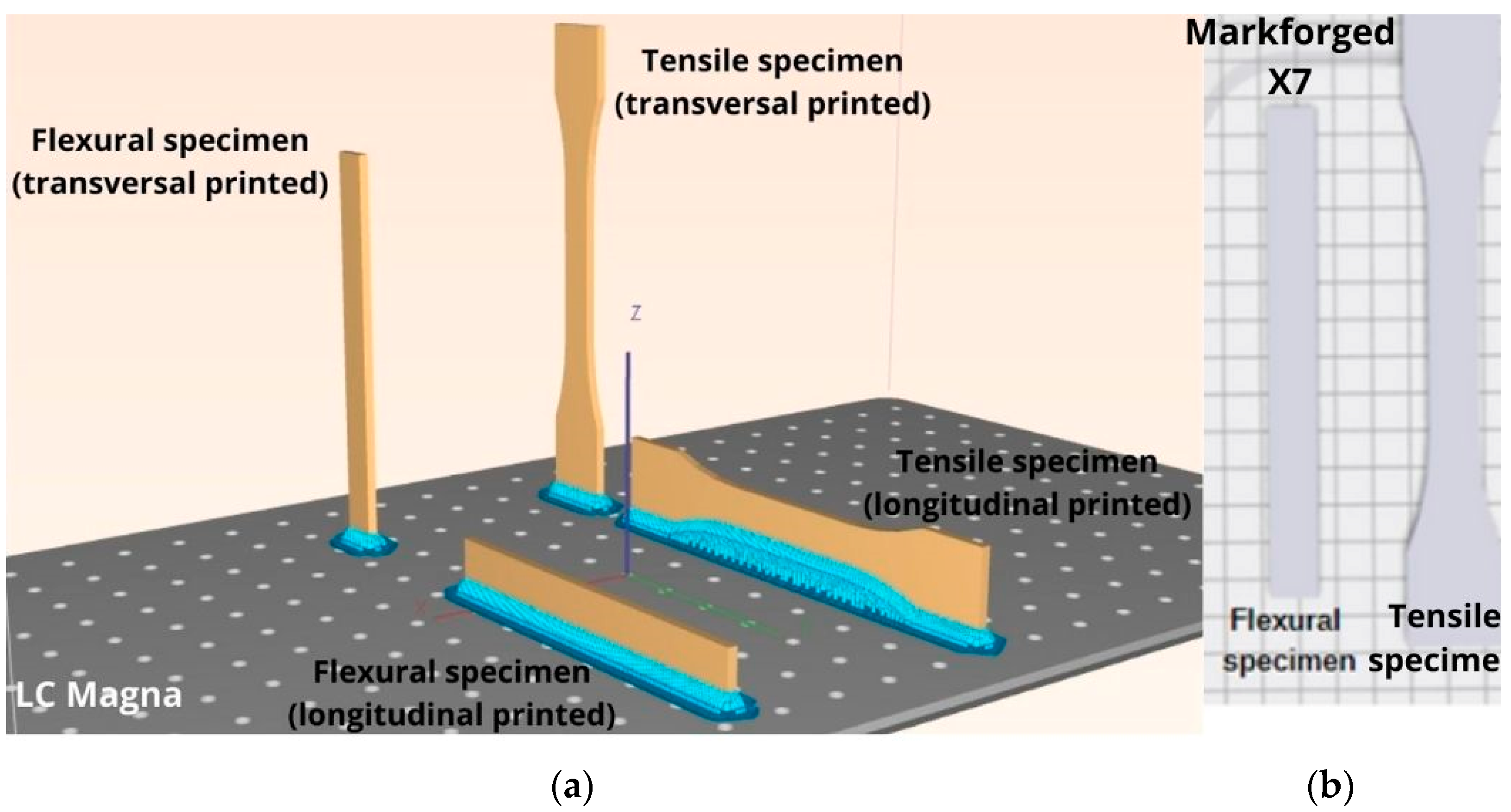
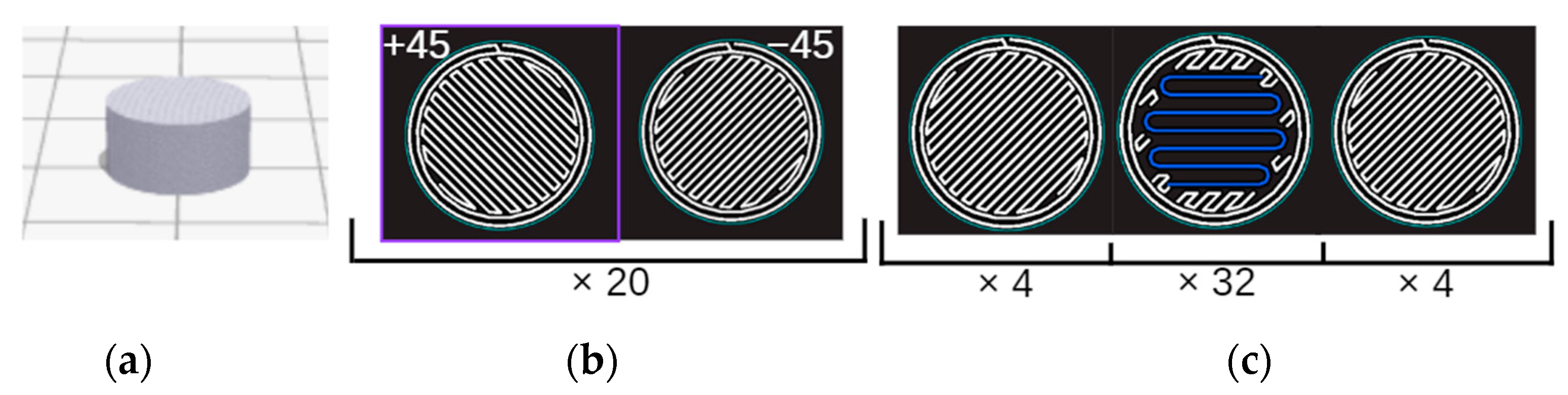
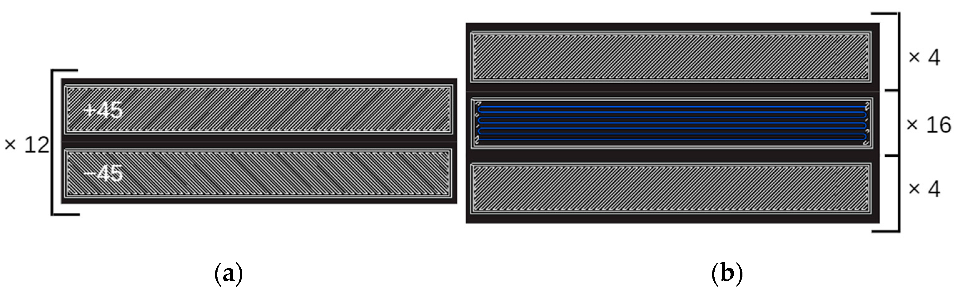
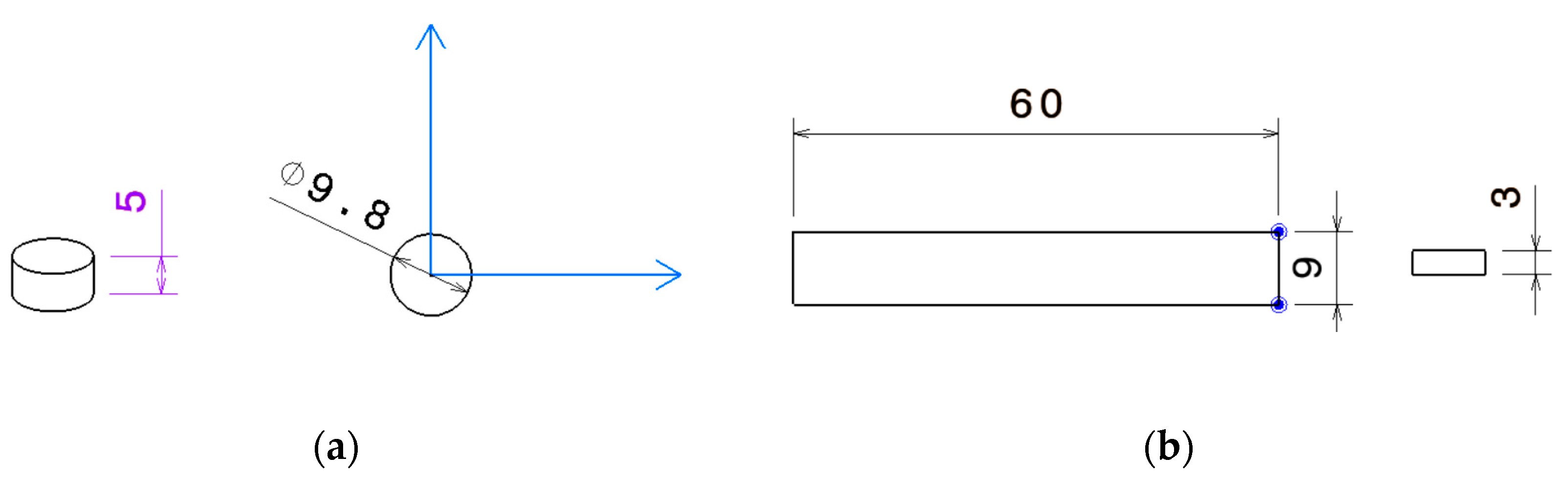
2.1. Materials and Fabrication Methods
2.2. DMA, TMA Analysis and Static Mechanical Test Methods
3. Results and Discussions
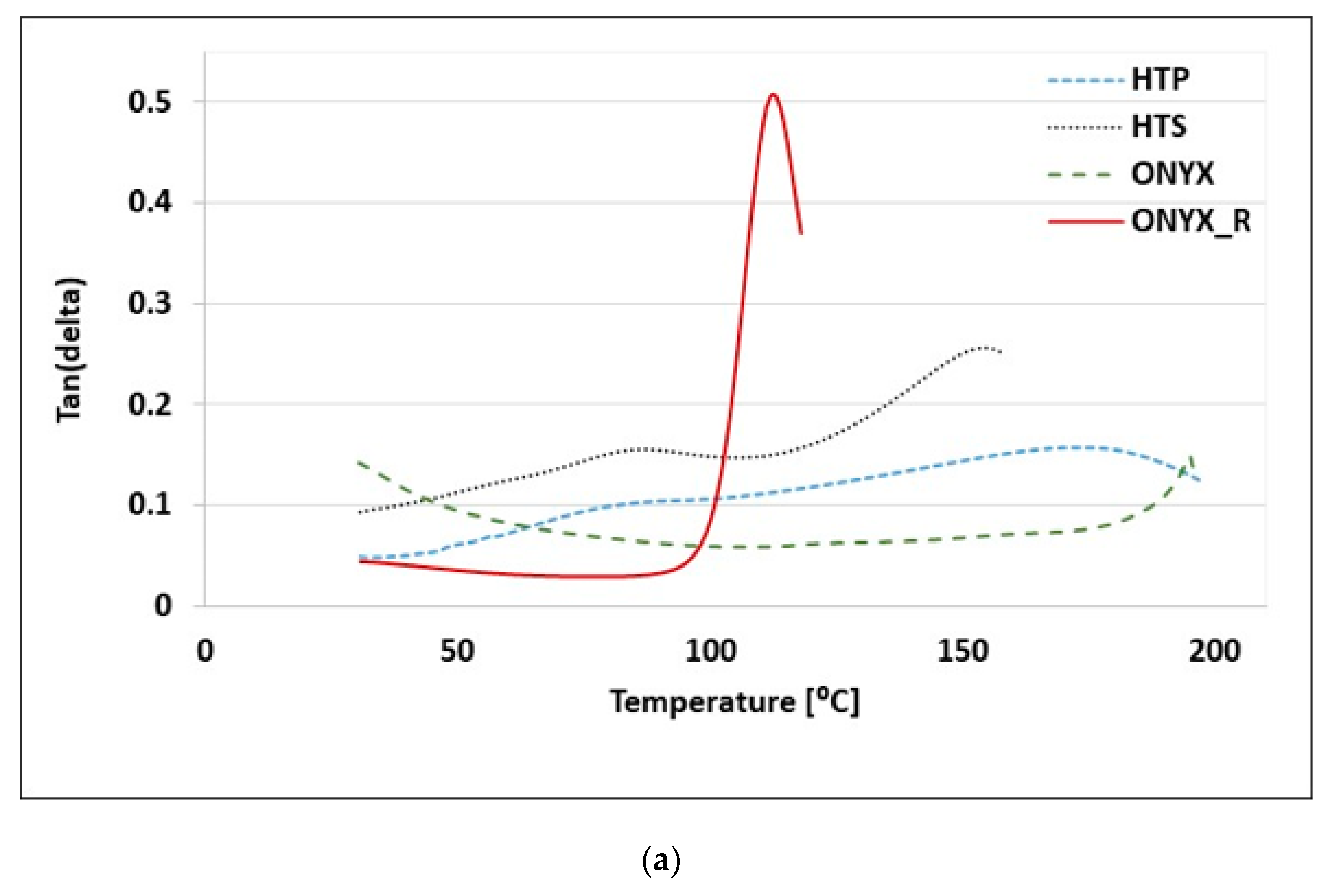
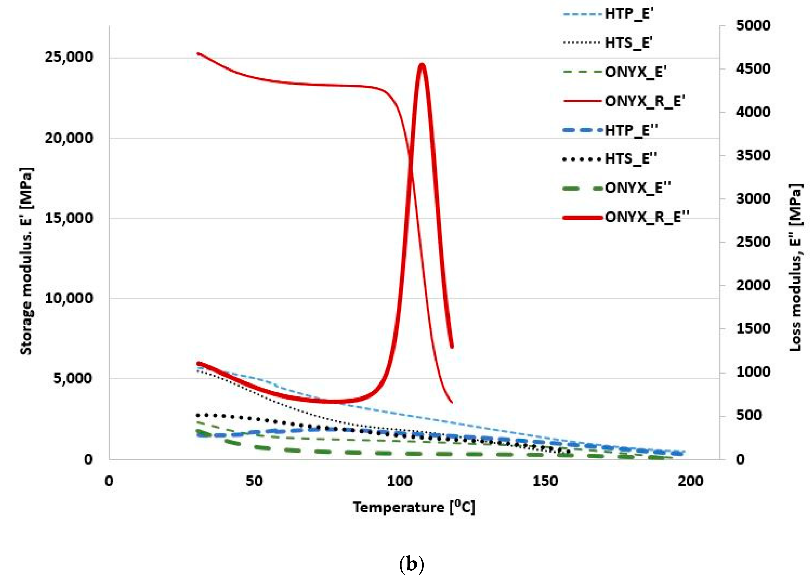
3.1. DMA Results
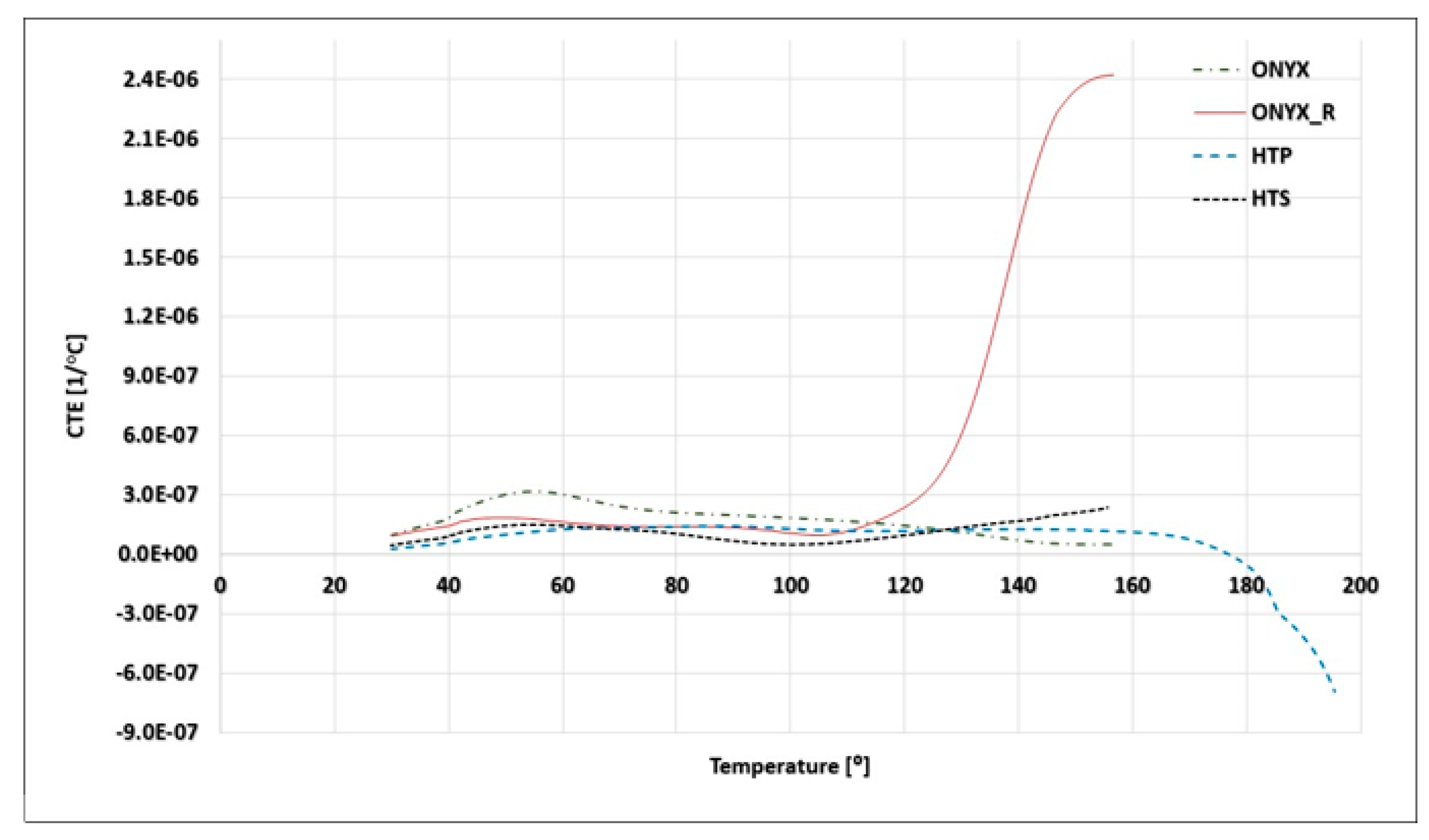
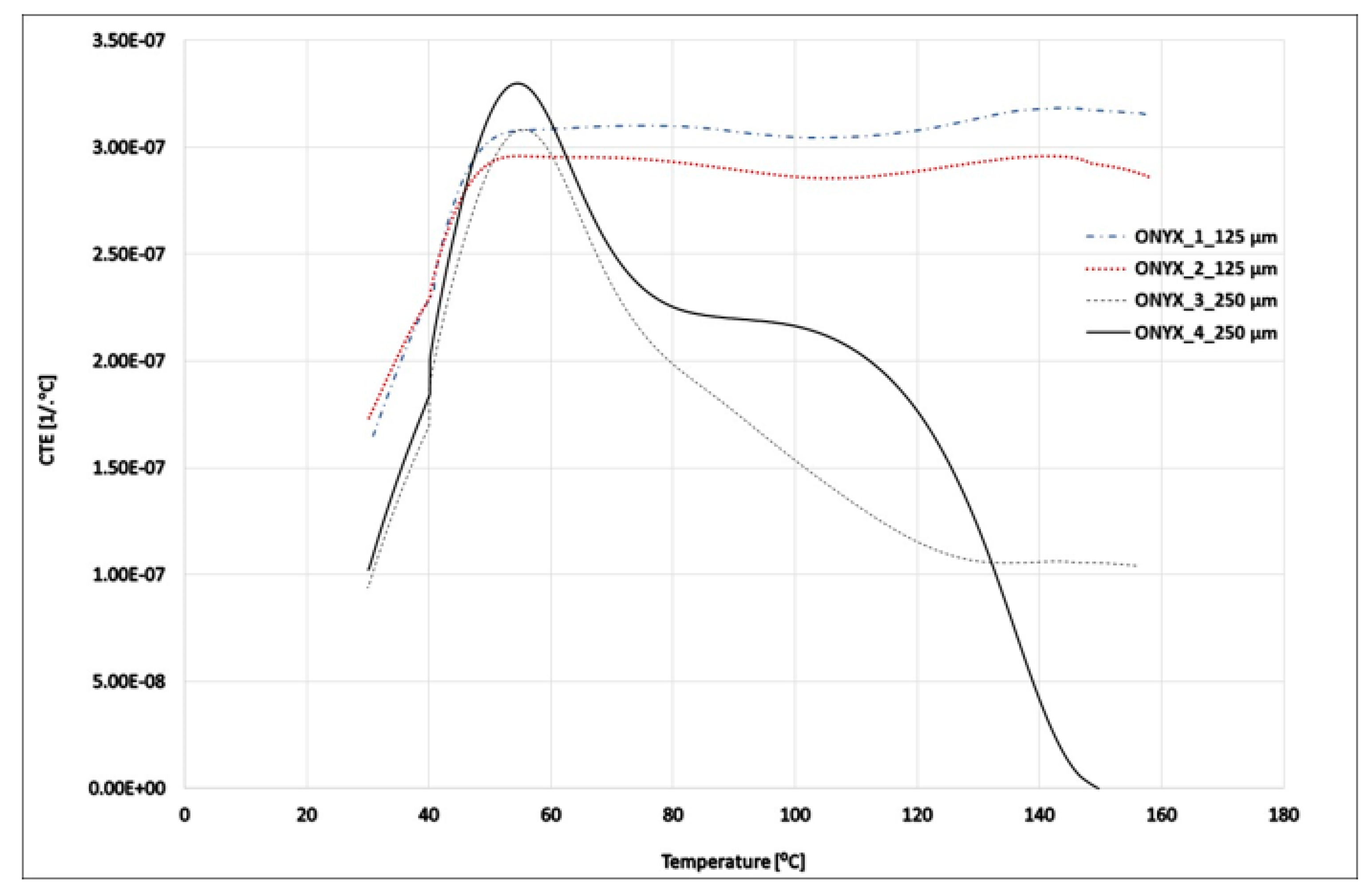
3.2. TMA Results
3.3. Tensile and Three-Point Bending Mechanical Results
4. Conclusions
Author Contributions
Funding
Institutional Review Board Statement
Informed Consent Statement
Data Availability Statement
Conflicts of Interest
References
- Ahn, S.H.; Lee, K.T.; Kim, H.J. Smart soft composite: An integrated 3D soft morphing structure using bend-twist coupling of anisotropic materials. Int. J. Precis. Eng. Manuf. 2012, 13, 631–634. [Google Scholar] [CrossRef]
- Ahmed, N.A.; Page, J.R. Manufacture of an unmanned aerial vehicle (UAV) for advanced project design using 3D printing technology. Appl. Mech. Mater. 2013, 397, 970–980. [Google Scholar] [CrossRef]
- Wu, C.S.; Liao, H.T.; Cai, Y.X. Characterisation, biodegradability and application of palm fibre-reinforced polyhydroxyalkanoate composites. Polym. Degrad. Stab. 2017, 140, 55–63. [Google Scholar] [CrossRef]
- Bos, F.; Wolfs, R.; Ahmed, Z. Additive manufacturing of concrete in construction: Potentials and challenges of 3D concrete printing. Virtual Phys. Prototyp. 2016, 11, 209–225. [Google Scholar] [CrossRef] [Green Version]
- Kavita, M.; Fijul Kabir, S.M.; Seyam, A.F. Tensile properties of 3D printed continuous fiberglass reinforced cellular composites. J. Text. Inst. 2022, 113, 60–69. [Google Scholar] [CrossRef]
- Kabir, S.M.F.; Mathur Seyam, A.F. Impact resistance and failure mechanism of 3D printed continuous fiber-reinforced cellular composites. J. Text. Inst. 2021, 112, 752–766. [Google Scholar] [CrossRef]
- Al Abadi, H.; Thai, H.T.; Paton-Cole, V.; Parel, V.I. Elastic properties of 3D printed fibre-reinforced structures. Compos. Struct. 2018, 193, 8–18. [Google Scholar] [CrossRef]
- Stoof, D.; Pickering, K. Sustainable composite fused deposition modelling filament using recycled pre-consumer polypropylene. Compos. Part B. Eng. 2018, 135, 110–118. [Google Scholar] [CrossRef]
- Chekal, J. Study of 3D-Printed Polymers for Aerospace Structural Applications. Master’s Thesis, University of Washington, Washington, DC, USA, 2021. [Google Scholar]
- Turner, B.N.; Gold, S.A. A review of melt extrusion additive manufacturing processes: II. Materials, dimensional accuracy, and surface roughness. Rapid Prototyp. J. 2015, 21, 250–261. [Google Scholar] [CrossRef]
- Turner, B.N.; Strong, R.; Gold, S.A. A review of melt extrusion additive manufacturing processes: I. Process design and modeling. Rapid Prototyp. J. 2014, 20, 192–204. [Google Scholar] [CrossRef]
- Ahn, S.H.; Montero, M.; Odell, D.; Roundy, S.; Wright, P.K. Anisotropic material properties of fused deposition modeling ABS. Rapid Prototyp. J. 2002, 8, 248–257. [Google Scholar] [CrossRef] [Green Version]
- Li, L.; Sun, Q.; Bellehumeur, C.; Gu, P. Investigation of bond formation in FDM process, solid free. Fabr. Proc. 2002, 403, 400–407. [Google Scholar] [CrossRef]
- Wu, W.; Geng, P.; Li, G.; Zhao, D.; Zhang, H.; Zhao, J. Influence of layer thickness and raster angle on the mechanical properties of 3D-printed PEEK and a comparative mechanical study between PEEK and ABS. Materials 2015, 8, 5834–5846. [Google Scholar] [CrossRef]
- František, B.; Milan, V.; Milan, S.; Marián, H.; Alzebeta, S. Mechanical properties of structures produced by 3D printing from composite materials. MATEC Web Conf. 2019, 254, 01018. [Google Scholar] [CrossRef]
- Sauer, M.J. Evaluation of the Mechanical Properties of 3D Printed Carbon Fiber Composites. Master’s Thesis, South Dakota State University, Brookings, SD, USA, 2018. [Google Scholar]
- Yi, C.; Jiang, L.; Qing, G.; Lei, W. 3D printing of CF/nylon composite mold for CF/epoxy parabolic antenna. J. Eng. Fibers Fabrics. 2020, 15, 1558925020969484. [Google Scholar]
- Lozano, A.B.; Álvarez, S.H.; Isaza, C.V.; Montealegre-Rubio, W. Analysis and Advances in Additive Manufacturing as a New Technology to Make Polymer Injection Molds for World-Class Production Systems. Polymers 2022, 14, 1646. [Google Scholar] [CrossRef]
- ASTM D 5023-07; Standard Test Method for Plastics: Dynamic Mechanical Properties: In Flexure (Three-Point Bending). ASTM International: West Conshohocken, PA, USA, 2007.
- ASTM E 831-06; Standard Test Method for Linear Thermal Expansion of Solid Materials by Thermomechanical Analysis. ASTM International: West Conshohocken, PA, USA, 2006.
- Pascual-Gonzalez, C.; Iragi, M.; Fernandez, A.; Fernandez-Blazquez, J.P.; Aretxabaleta, L.; Lopes, C.S. An approach to analyse the factors behind the micromechanical response of 3D-printed composites. Compos. Part B Eng. 2020, 186, 107820. [Google Scholar] [CrossRef]
- MarkForged®, Mechanical Properties. 2022. Available online: https://www-objects.markforged.com/craft/materials/CompositesV5.2.pdf (accessed on 1 June 2022).
- Mullholand, T.; Goris, S.; Boxleitner, J.; Osswald, T.A.; Rudolph, N. Fiber Orientation Effects in Fused Filament Fabrication of Air-Cooled Heat Exchangers. JOM 2018, 60, 298–302. [Google Scholar] [CrossRef]
- Crompton, T.R. Physical Testing of Plastics, 1st ed.; Smithers Rapra Technology Ltd.: Shrewsbury, UK, 2012; pp. 171–173. [Google Scholar]
- Klein, N.; Marom, G.; Wachtel, E. Microstructure of nylon 66 transcrystalline layers in carbon and aramid fibre reinforced composites. Polymer 1996, 37, 5493–5498. [Google Scholar] [CrossRef]
- Almagableh, A.; Gupta, S.; Mantena, P.R.; Al-Ostaz, A. Dynamic Mechanical Analysis of Graphite Platelet and Nanoclay Reinforced Vinyl Ester, and MWCNT Reinforced Nylon 6,6 Nanocomposites. Composite Structures and Nano-Engineering Research, The University of Mississippi. Personal communication. In Proceedings of the 40th ISTC, Memphis, TN, USA, 8–11 September 2008. [Google Scholar]
- Milward, S. Investigation into Additive Manufacturing for Controlling Thermal Expansion in Optical Applications. Ph.D. Thesis, Swansea University, Swansea, UK, 2020. [Google Scholar]
- Faust, J.L.; Kelly, P.G.; Jones, B.D.; Roy-Mayhew, J.D. Effects of Coefficient of Thermal Expansion and Moisture Absorption on the Dimensional Accuracy of Carbon-Reinforced 3D Printed Parts. Polymers 2021, 13, 3637. [Google Scholar] [CrossRef]
- Farbman, D.; McCoy, C. Materials Testing of 3D Printed ABS and PLA Samples to Guide Mechanical Design. In Proceedings of the ASME 2016 International Manufacturing Science and Engineering Conference MSEC, Blacksburg, VA, USA, 27 June–1 July 2016. [Google Scholar]
- Ekoi, E.J.; Dickson, A.N.; Dowling, D.P. Investigating the fatigue and Mechanical Behaviour of 3D Printed woven and Nonwoven Continuous Carbon Fibre Reinforced Polymer (CFRP) Composites. Compos. Part B Eng. 2021, 212, 108796. [Google Scholar] [CrossRef]
- Parmiggiani, A.; Prato, M.; Pizzorni, M. Effect of the fiber orientation on the tensile and flexural behavior of continuous carbon fiber composites made via fused filament fabrication. Int. J. Adv. Manuf. Technol. 2021, 114, 2085–2101. [Google Scholar] [CrossRef]
- Ghebretinase, F. Mechanical Testing and Finite Element Analysis Of 3D Printed Continuous Carbon Fiber ONYX® Thermoplastic. Master’s Thesis, Universitet i Stavanger, Stavanger, Norway, 2019. [Google Scholar]
- Ma, C.; Faust, J.; Roy-Mayhew, J.D. Drivers of mechanical performance variance in 3D-printed fused filament fabrication parts: An ONYX FR case study. Polym. Compos. 2021, 42, 4786–4794. [Google Scholar] [CrossRef]
- Sanei, S.H.R.; Lash, Z.; Servey, J.; Gardone, F.; Nikhare, C.P. Draft: Mechanical Properties of 3D Printed Fiber Reinforced Thermoplastic. In Proceedings of the ASME 2019 International Mechanical Engineering Congress and Exposition IMECE2019, Salt Lake City, UT, USA, 8–14 November 2019. [Google Scholar] [CrossRef]
- Iragi, M.; Pascual-Gonzalez, C.; Esnaola, A.; Aurrekoetxea, J.; Lopes, C.S.; Aretxabaleta, L. Characterization of Elastic and Resistance Behaviours of 3D Printed Continuous Carbon Fibre Reinforced Thermoplastics. In Proceedings of the ECCM18—18th European Conference on Composite Materials, Athens, Greece, 24–28 June 2018. [Google Scholar]
- Hanon, M.M.; Ghaly, A.; Zsidai, L.; Szakál, Z.; Szabó, I.; Kátai, L. Investigations of the Mechanical Properties of DLP 3D Printed Graphene/Resin Composites. Acta Polytech. Hung. 2021, 18, 143–161. [Google Scholar] [CrossRef]
- Composite Laboratory of Aarhus University. Available online: https://ingenioer.au.dk/fileadmin/www.ase.au.dk/Filer/Laboratorier_og_vaerksteder/Komposit-lab/3D_Print/ONYX_Filament_-_TDS.pdf (accessed on 1 June 2022).
- ASTM D 3039/D 3039 M-00; Standard Test Method for Tensile Properties of Polymer Matrix Composite Materials. ASTM International: West Conshohocken, PA, USA, 2008.
- Hua, W.; Lin, Q.; Qu, B.; Zheng, Y.; Liu, X.; Li, W.; Zhao, X.; Chen, S.; Zhuo, D. Exceptional Mechanical Properties and Heat Resistance of Photocurable Bismaleimide Ink for 3D Printing. Materials 2021, 14, 1708. [Google Scholar] [CrossRef] [PubMed]


| Reinforced ONYX Specimens | |||||
|---|---|---|---|---|---|
| ONYX Nozzle Temperature | Carbon Fiber Nozzle Temperature | Layer Thickness | Infill | ONYX Layer Orientation | Carbon Fiber Orientation |
| 275 °C | 252 °C | 0.125 mm | 100% | ±45° | 0° |
| ONYX Specimens | |||
|---|---|---|---|
| ONYX Nozzle Temperature | Layer Thickness | Infill | ONYX Layer Orientation |
| 275 °C | 0.1 mm | 100% | ±45° |
| Material/Sample | ONYX | ONYX_R | HTP | HTS |
|---|---|---|---|---|
| Tan δ | 0.1413 0.1785 - - | 0.5208 0.4993 - - | 0.1594 0.1589 0.1563 0.1482 | 0.2554 0.1467 0.2614 0.2527 |
| Storage modulus [MPa] | 2120.1 2487.1 - - | 25,447 25,011 - - | 6186.4 5466.4 55,439.4 5328 | 5597.1 5717.4 5370.8 5418 |
| Loss modulus [MPa] | 269.16 387.21 - - | 4537.4 4562.7 - - | 538.92 332.17 358.95 346.35 | 515.36 623.43 515.96 487.56 |
| Material/Sample | ONYX | HTP | HTS |
|---|---|---|---|
| CTE [10−6 1/°C] | 318.4 (125 µm) 296 (125 µm) 308.4 (250 µm) 330 (250 µm) | 147.4 144.5 141.3 - | 271.7 265.3 177.3 - |
| Mean | 313.2 | 144.4 | 238.1 |
| SD | 14.47 | 3.05 | 52.75 |
| Std. Error | 7.23 | 1.76 | 30.45 |
| Material/Sample | ONYX | ONYX_R | HTS_L | HTS_T | HTP_L | HTP_T |
|---|---|---|---|---|---|---|
| Flexural Strength [MPa] | 42.06 | 174.37 | 77.13 | 68.39 | 75.591 | 82.205 |
| 41.47 | 176.08 | 77.48 | 64.84 | 68.976 | 70.866 | |
| 39.65 | 176.81 | 79.25 | 64.61 | 74.528 | 75.118 | |
| 39.32 | - | 82.56 | 64.84 | 72.165 | - | |
| 38.32 | - | 78.54 | - | - | - | |
| Mean | 40.16 | 175.75 | 78.99 | 65.67 | 72.81 | 76.06 |
| SD | 2.42 | 1.58 | 4.69 | 3.3 | 8.6 | 32.81 |
| CV [%] | 6.03 | 0.9 | 5.94 | 5.03 | 11.81 | 43.14 |
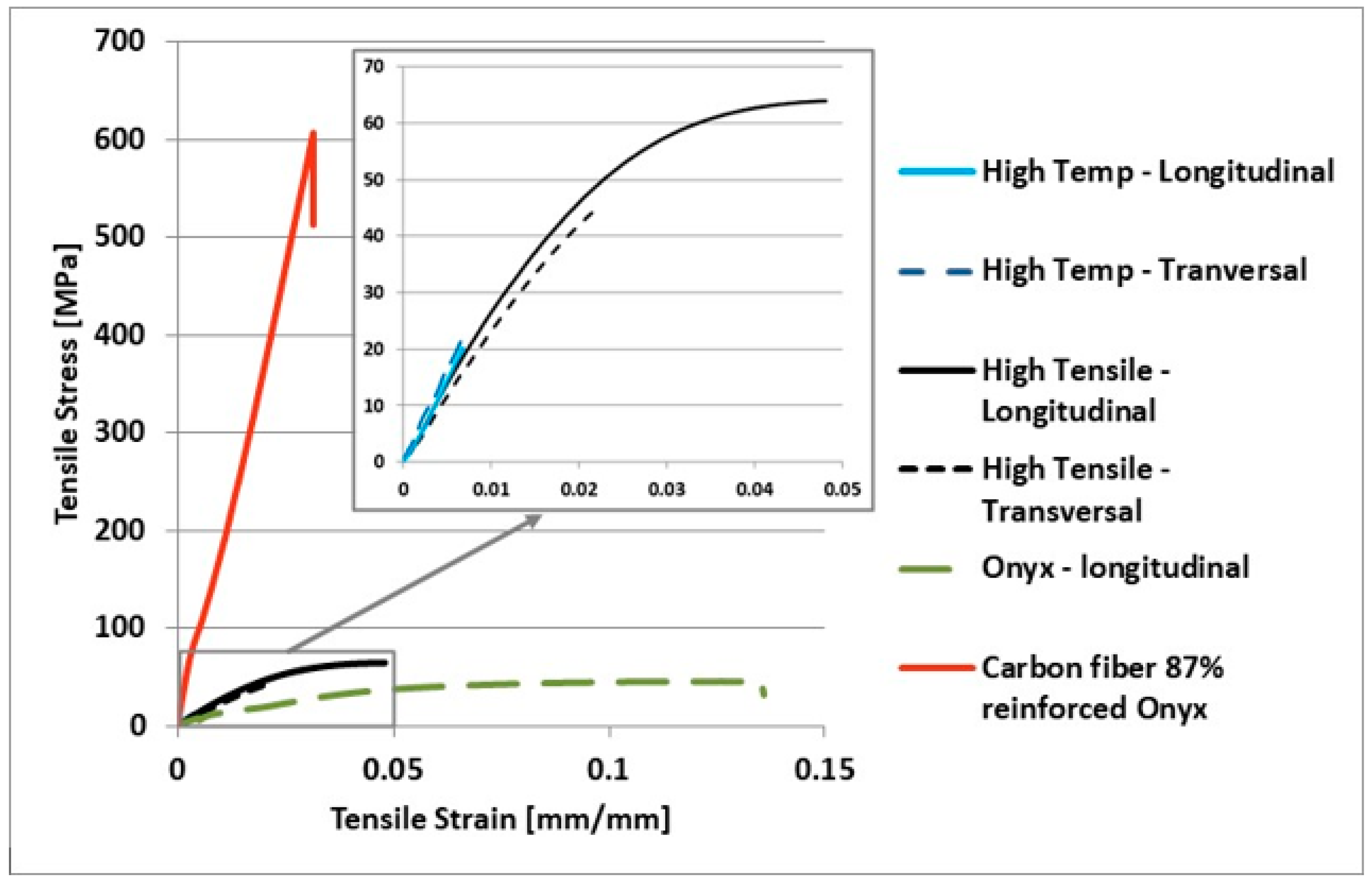
| Material/Sample | ONYX | ONYX_R | HTS_L | HTS_T | HTP_L | HTP_T |
|---|---|---|---|---|---|---|
| Tensile Strength [MPa] | 46.23 | 621.9 | 61.16 | 58.06 | 27.36 | 36.61 |
| 44.97 | 615.24 | 67.48 | 61.87 | 27.62 | 43.32 | |
| 49.84 | 622.63 | 68.77 | 52.54 | 23.79 | 35.06 | |
| 44.54 | 628.356 | 63.93 | 52.40 | - | - | |
| 44.51 | - | - | 53.65 | - | - | |
| Mean | 46.02 | 622.03 | 65.33 | 55.7 | 26.26 | 38.33 |
| SD | 5.05 | 28.83 | 11.94 | 17.17 | 4.58 | 19.28 |
| CV [%] | 10.98 | 4.64 | 18.28 | 30.82 | 17.44 | 50.29 |
Publisher’s Note: MDPI stays neutral with regard to jurisdictional claims in published maps and institutional affiliations. |
© 2022 by the authors. Licensee MDPI, Basel, Switzerland. This article is an open access article distributed under the terms and conditions of the Creative Commons Attribution (CC BY) license (https://creativecommons.org/licenses/by/4.0/).
Share and Cite
Maier, R.; Istrate, A.M.; Despa, A.; Mandoc, A.C.; Bucaciuc, S.; Stoica, R. Investigation into Thermomechanical Response of Polymer Composite Materials Produced through Additive Manufacturing Technologies. Materials 2022, 15, 5069. https://doi.org/10.3390/ma15145069
Maier R, Istrate AM, Despa A, Mandoc AC, Bucaciuc S, Stoica R. Investigation into Thermomechanical Response of Polymer Composite Materials Produced through Additive Manufacturing Technologies. Materials. 2022; 15(14):5069. https://doi.org/10.3390/ma15145069
Chicago/Turabian StyleMaier, Raluca, Anca Mihaela Istrate, Alexandra Despa, Andrei Cristian Mandoc, Sebastian Bucaciuc, and Romică Stoica. 2022. "Investigation into Thermomechanical Response of Polymer Composite Materials Produced through Additive Manufacturing Technologies" Materials 15, no. 14: 5069. https://doi.org/10.3390/ma15145069
APA StyleMaier, R., Istrate, A. M., Despa, A., Mandoc, A. C., Bucaciuc, S., & Stoica, R. (2022). Investigation into Thermomechanical Response of Polymer Composite Materials Produced through Additive Manufacturing Technologies. Materials, 15(14), 5069. https://doi.org/10.3390/ma15145069