
Wall Fabrication by Direct Energy Deposition (DED) Combining Mild Steel (ER70) and Stainless Steel (SS 316L): Microstructure and Mechanical Properties

 , , , and
Abstract
:1. Introduction
2. Materials and Methods
3. Results
3.1. Preliminary Tests
3.1.1. Mild Steel GMAW–WAAM
3.1.2. Stainless Steel PAW–WAAM
3.2. Bimetallic Wall Manufactured by DED
4. Conclusions
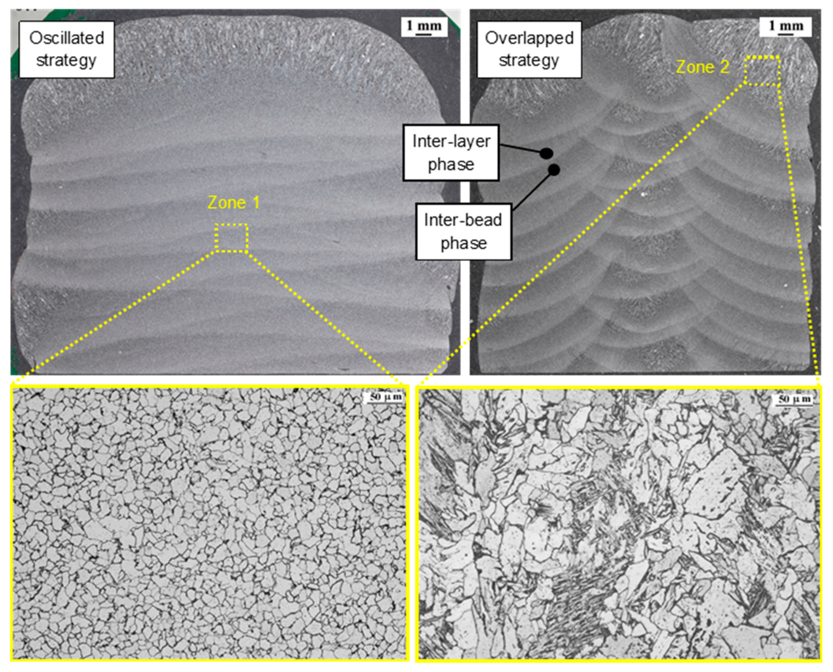
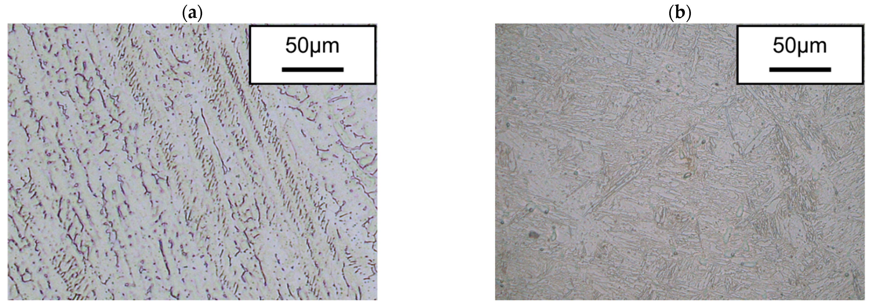
- It was proved that bimetallic walls can be manufactured without any considerable defect in the intermetallic zone. No visual defects, no pores and no cracks are observed in the microstructure. Bimetallic walls preserve the microstructure corresponding to each material separately, being interesting in applications where specific properties are required at specific locations.
- The hardness observed in the materials in both strategies is similar, being about 380 HV for ER70 and around 180 HV for SS 316L.
- The specimens from the two strategies were mechanically characterized. It was found that the percentage of steel type in the specimen is decisive. The average values of the ultimate tensile strength (UTS) are 869 and 628 MPa, the yield strength (YS) is 584 and 389 MPa and the elongation at break is 20% and 36%. The former values correspond to the cases with higher % ER70-6, and the latter to those with higher % SS 316. This indicates an important relationship between the distribution of the materials and their mechanical behavior.
- A high incidence of both the deposition strategy and the internal arrangement of the materials in the specimen was observed. The specimens with a higher amount of SS 316L (overlapped walls) show a higher elongation and a lower maximum stress at break.
Author Contributions
Funding
Data Availability Statement
Conflicts of Interest
References
- Kannan, A.R.; Kumar, S.M.; Pramod, R.; Kumar, N.P.; Shanmugam, N.S.; Palguna, Y. Microstructure and mechanical properties of wire arc additive manufactured bi-metallic structure. Sci. Technol. Weld. Join. 2020, 26, 47–57. [Google Scholar] [CrossRef]
- Wu, B.; Qiu, Z.; Pan, Z.; Carpenter, K.; Wang, T.; Ding, D.; Van Duin, S.; Li, H. Enhanced interface strength in steel-nickel bimetallic component fabricated using wire arc additive manufacturing with interweaving deposition strategy. J. Mater. Sci. Technol. 2020, 52, 226–234. [Google Scholar] [CrossRef]
- Ahsan, R.U.; Tanvir, A.N.M.; Ross, T.; ElSawy, A.; Oh, M.-S.; Kim, D.B. Fabrication of bimetallic additively manufactured structure (BAMS) of low carbon steel and 316L austenitic stainless steel with wire + arc additive manufacturing. Rapid Prototyp. J. 2019, 26, 519–530. [Google Scholar] [CrossRef]
- Moritz, T.; Scheithauer, U.; Weingarten, S.; Abel, J.; Johne, R.; Michaelis, A.; Hampel, S.; Cano, S.C. Hybridization of materials and processes by additive manufacturing. In Proceedings of the 3rd International Conference on Progress in Additive Manufacturing, Singapore, 14–17 May 2018; pp. 10–17. [Google Scholar] [CrossRef]
- Kumar, S.M.; Kannan, A.R.; Kumar, N.P.; Pramod, R.; Shanmugam, N.S.; Vishnu, A.S.; Channabasavanna, S.G. Microstructural Features and Mechanical Integrity of Wire Arc Additive Manufactured SS321/Inconel 625 Functionally Gradient Material. J. Mater. Eng. Perform. 2021, 30, 5692–5703. [Google Scholar] [CrossRef]
- Wang, J.; Pan, Z.; Wang, L.; Su, L.; Carpenter, K.; Wang, J.; Wang, R.; Li, H. In-situ dual wire arc additive manufacturing of NiTi-coating on Ti6Al4V alloys: Microstructure characterization and mechanical properties. Surf. Coat. Technol. 2020, 386, 125439. [Google Scholar] [CrossRef]
- Liu, Z.; Zhang, D.; Sing, S.; Chua, C.; Loh, L. Interfacial characterization of SLM parts in multi-material processing: Metallurgical diffusion between 316L stainless steel and C18400 copper alloy. Mater. Charact. 2014, 94, 116–125. [Google Scholar] [CrossRef]
- Kotoban, D.; Aramov, A.; Tarasova, T. Possibility of Multi-material Laser Cladding Fabrication of Nickel Alloy and Stainless Steel. Phys. Procedia 2016, 83, 634–646. [Google Scholar] [CrossRef] [Green Version]
- Ramkumar, K.D.; Patel, S.D.; Praveen, S.S.; Choudhury, D.J.; Prabaharan, P.; Arivazhagan, N.; Xavior, M.A. Influence of filler metals and welding techniques on the structure–property relationships of Inconel 718 and AISI 316L dissimilar weldments. Mater. Des. 2014, 62, 175–188. [Google Scholar] [CrossRef]
- Hinojos, A.; Mireles, J.; Reichardt, A.; Frigola, P.; Hosemann, P.; Murr, L.E.; Wicker, R.B. Joining of Inconel 718 and 316 Stainless Steel using electron beam melting additive manufacturing technology. Mater. Des. 2016, 94, 17–27. [Google Scholar] [CrossRef] [Green Version]
- Shakerin, S.; Hadadzadeh, A.; Amirkhiz, B.S.; Shamsdini, S.; Li, J.; Mohammadi, M. Additive manufacturing of maraging steel-H13 bimetals using laser powder bed fusion technique. Addit. Manuf. 2019, 29, 100797. [Google Scholar] [CrossRef]
- Leicher, M.; Kamper, S.; Treutler, K.; Wesling, V. Multi-material design in additive manufacturing—Feasibility validation. Weld. World 2020, 64, 1341–1347. [Google Scholar] [CrossRef]
- Watanabe, I.; Sun, Z.; Kitano, H.; Goto, K. Multiscale analysis of mechanical behavior of multilayer steel structures fabricated by wire and arc additive manufacturing. Sci. Technol. Adv. Mater. 2020, 21, 461–470. [Google Scholar] [CrossRef] [PubMed]
- Ahsan, R.U.; Tanvir, A.; Seo, G.-J.; Bates, B.; Hawkins, W.; Lee, C.; Liaw, P.; Noakes, M.; Nycz, A.; Kim, D.B. Heat-treatment effects on a bimetallic additively-manufactured structure (BAMS) of the low-carbon steel and austenitic-stainless steel. Addit. Manuf. 2020, 32, 101036. [Google Scholar] [CrossRef]
- Aldalur, E.; Veiga, F.; Suárez, A.; Bilbao, J.; Lamikiz, A. Analysis of the Wall Geometry with Different Strategies for High Deposition Wire Arc Additive Manufacturing of Mild Steel. Metals 2020, 10, 892. [Google Scholar] [CrossRef]
- EN ISO 6892-1:2019; Metallic Materials—Tensile Testing—Part 1: Method of Test at Room Temperature. ISO: Geneva, Switzerland, 2019.
- Aldalur, E.; Veiga, F.; Suárez, A.; Bilbao, J.; Lamikiz, A. High deposition wire arc additive manufacturing of mild steel: Strategies and heat input effect on microstructure and mechanical properties. J. Manuf. Process. 2020, 58, 615–626. [Google Scholar] [CrossRef]
- Rafieazad, M.; Ghaffari, M.; Nemani, A.V.; Nasiri, A. Microstructural evolution and mechanical properties of a low-carbon low-alloy steel produced by wire arc additive manufacturing. Int. J. Adv. Manuf. Technol. 2019, 105, 2121–2134. [Google Scholar] [CrossRef]
- Huang, C.; Kyvelou, P.; Zhang, R.; Ben Britton, T.; Gardner, L. Mechanical testing and microstructural analysis of wire arc additively manufactured steels. Mater. Des. 2022, 216, 110544. [Google Scholar] [CrossRef]
- Sun, L.; Jiang, F.; Huang, R.; Yuan, D.; Guo, C.; Wang, J. Anisotropic mechanical properties and deformation behavior of low-carbon high-strength steel component fabricated by wire and arc additive manufacturing. Mater. Sci. Eng. A 2020, 787, 139514. [Google Scholar] [CrossRef]
- Suárez, A.; Aldalur, E.; Veiga, F.; Artaza, T.; Tabernero, I.; Lamikiz, A. Wire arc additive manufacturing of an aeronautic fitting with different metal alloys: From the design to the part. J. Manuf. Process. 2021, 64, 188–197. [Google Scholar] [CrossRef]


| C | Si | Mn | Cr | Ni | Cu | P | Mo | S | Ti | Al | Co | Fe | |
|---|---|---|---|---|---|---|---|---|---|---|---|---|---|
| ER70S-6 | 0.06 | 0.94 | 1.64 | 0.02 | 0.02 | 0.02 | 0.013 | 0.005 | 0.016 | 0.004 | - | - | bal. |
| SS 316L | 0.007 | 0.81 | 1.6 | 18.26 | 12.11 | 0.09 | 0.019 | 2.53 | 0.013 | 0.003 | 0.003 | 0.064 | bal. |
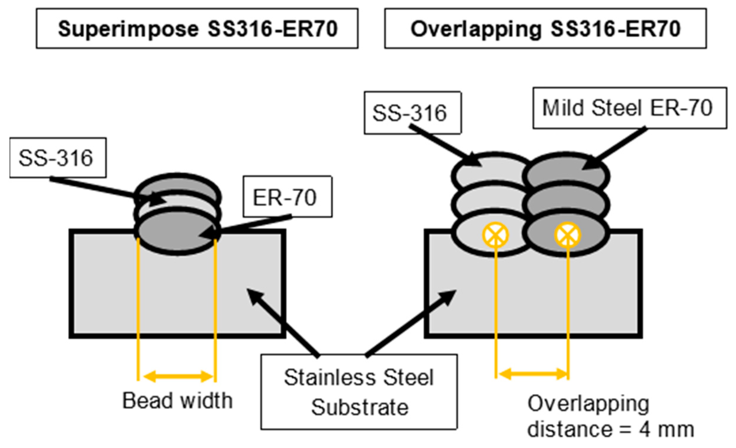
| Strategy | Technology | Material | Wire Feed Rate WFR (m/min) | Travel Speed TS (cm/min) | I (A) | V (V) | Overlapping Distance (mm) |
|---|---|---|---|---|---|---|---|
| Superimposed wall | PAW | SS 316L | 3.5 | 35 | 250 | 14.5 | - |
| GMAW | ER70S-6 | 3.5 | 35 | 120 | 23 | ||
| Overlapped wall | PAW | SS 316L | 3.5 | 35 | 250 | 14.5 | 4 |
| GMAW | ER70S-6 | 3.5 | 45 | 120 | 23 |
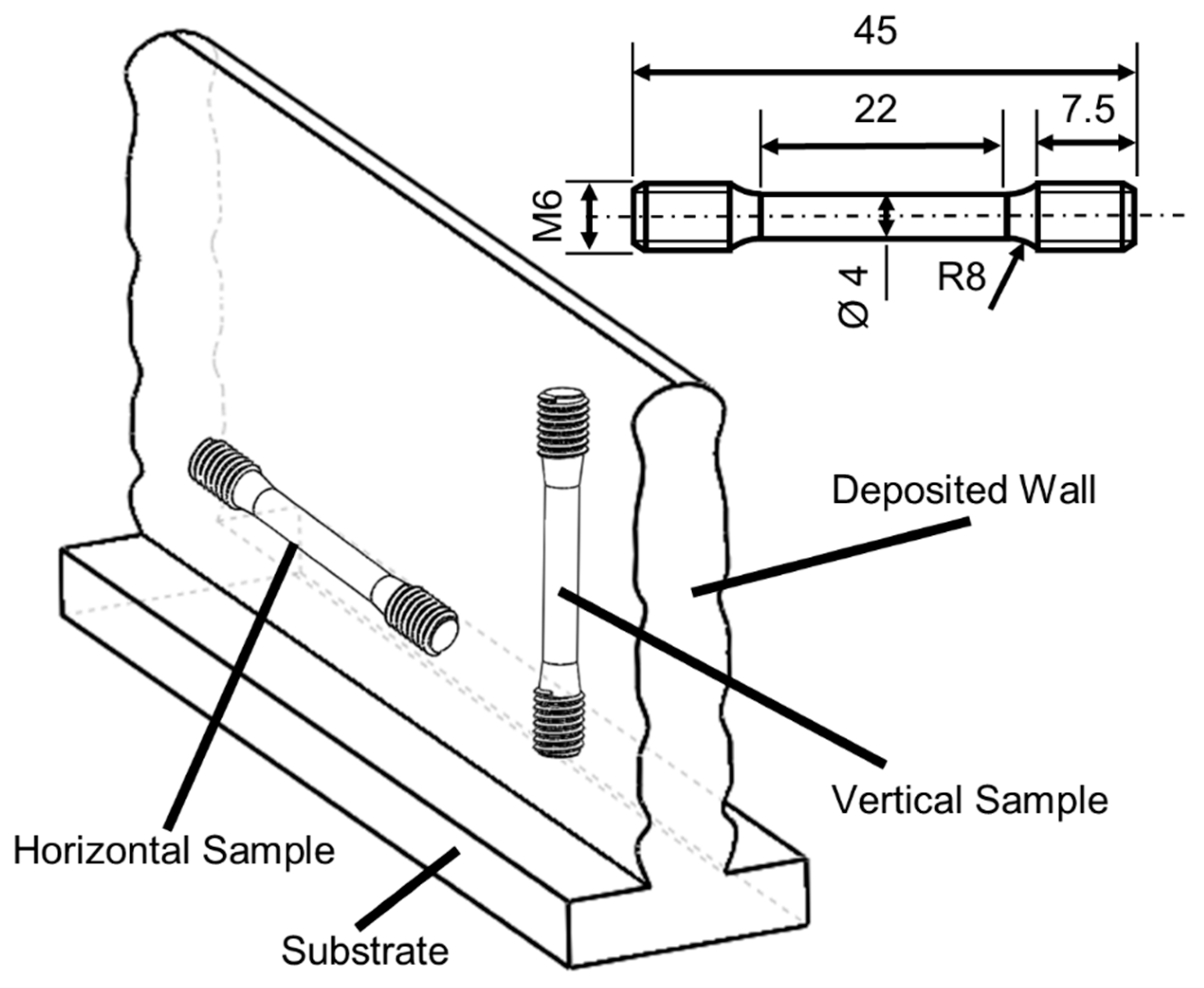
| Tensile Test | ||||
|---|---|---|---|---|
| UTS (MPa) | YS 0.2% (MPa) | Elong. (%) | ||
| ER70 WAAM | Horizontal | 498 ± 9 | 368 ± 12 | 36 ± 4 |
| Vertical | 501 ± 3 | 368 ± 4 | 32 ± 1 | |
| ER70 as welded | - | 500–640 | >420 | 28 |
| Tensile Test | ||||
|---|---|---|---|---|
| UTS (MPa) | YS 0.2% (MPa) | Elong. (%) | ||
| SS 316L WAAM | Horizontal | 581 ± 10 | 381 ± 15 | 38 ± 4 |
| Vertical | 534 ± 9 | 341 ± 6 | 52 ± 11 | |
| SS 316L as welded | - | >525 | >220 | 45 |
| Hardness Test (HV) | ||||
|---|---|---|---|---|
| Superimposed Wall | Overlapped Wall | |||
| Mean | SD | Mean | SD | |
| SS 316L WAAM | 178 | 9 | 186 | 10 |
| ER70 WAAM | 385 | 16 | 379 | 7 |
Publisher’s Note: MDPI stays neutral with regard to jurisdictional claims in published maps and institutional affiliations. |
© 2022 by the authors. Licensee MDPI, Basel, Switzerland. This article is an open access article distributed under the terms and conditions of the Creative Commons Attribution (CC BY) license (https://creativecommons.org/licenses/by/4.0/).
Share and Cite
Uralde, V.; Suarez, A.; Aldalur, E.; Veiga, F.; Ballesteros, T. Wall Fabrication by Direct Energy Deposition (DED) Combining Mild Steel (ER70) and Stainless Steel (SS 316L): Microstructure and Mechanical Properties. Materials 2022, 15, 5828. https://doi.org/10.3390/ma15175828
Uralde V, Suarez A, Aldalur E, Veiga F, Ballesteros T. Wall Fabrication by Direct Energy Deposition (DED) Combining Mild Steel (ER70) and Stainless Steel (SS 316L): Microstructure and Mechanical Properties. Materials. 2022; 15(17):5828. https://doi.org/10.3390/ma15175828
Chicago/Turabian StyleUralde, Virginia, Alfredo Suarez, Eider Aldalur, Fernando Veiga, and Tomas Ballesteros. 2022. "Wall Fabrication by Direct Energy Deposition (DED) Combining Mild Steel (ER70) and Stainless Steel (SS 316L): Microstructure and Mechanical Properties" Materials 15, no. 17: 5828. https://doi.org/10.3390/ma15175828