
Research on Filling Strategy of Pipeline Multi-Layer Welding for Compound Narrow Gap Groove
Abstract
:1. Introductions
2. Weld Bead Filling Strategy for the Cross-Sectional Area of Multi-Layer and Multi-Pass Welding of Pipeline
2.1. Basic Thought
- (1)
- Equal height methodThe equal height method is a method often used in pipeline welding in engineering. It only needs to meet the same layer height of each filling layer, that is, it needs to meet the following conditions:where i = 1, 2,…, n, n is the number of filling layers.The pipeline external welding robot’s motion planning and design just require setting the same value in the radial direction of the pipeline (i.e., the external welding robot’s lifting mechanism) every time.
- (2)
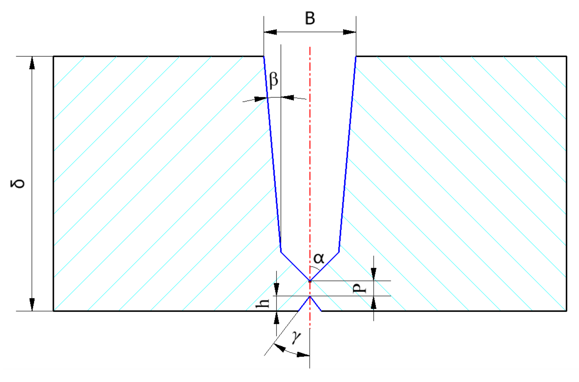
- Equal area methodThe equal area method needs to solve the welding layer height of the filling welding layer to set the lifting amount of the welding gun of the external welding robot. The cross-sectional area of each weld layer is equal, so the total area of the weld cross-section is:The recurrence relationship of weld width of adjacent weld layers is as follows:The relationship between the weld width of the initial weld layer and the maximum weld width of the weld is as follows:where, i = 1, 2,…, n, n is the number of filling layers.
2.2. Application Analysis of Equal Height Method and Equal Area Method
3. Establishment of Prediction Model of Uplift of Filling Layer of Large Diameter Pipeline
3.1. Estimation of Lifting Layers of Filling Layer of Large Diameter Pipeline
3.2. Calculation Process of Filling Amount of Each Layer of Filling Layer
- (1)
- Set the number of filling layers as n, and set the initial value n = 0; Set the height of each filling layer as H(i);
- (2)
- Determine the current remaining theoretical layer height h, and determine n_ max, n_min, and n_middle, respectively, according to Equations (10)–(12);
- (3)
- N_ middle is substituted into the equal area method to calculate each H(i) value under the equal area method;
- (4)
- The judge that h(i) is in the range of 2.5 mm~3.0 mm. If yes, record H(n + i) = H(i), 1 ≤ I ≤ n_ middle, and update the number of layers n = n + n_middle, output the number of layers n and all layer heights H(i) (1 ≤ i ≤ n), then end all calculations and enter end; If not, enter 4);
- (5)
- Judge whether h(1) is within the range of 2.5 mm~3.0 mm. If yes, enter (5); If not, enter (7);
- (6)
- Find when 1 < j < n_middle + 1, it meets the value i of h(j) ≥ 2.5 and h(j + 1) < 2.5; Record the value j at this time; Record h(n + I) = h(i), 1 ≤ i ≤ j; Update the value of n as n = n + j; Since the storey heights of the following floors from h(j + 1) to h (n_middle) are less than 2.5 mm, calculate the sum of storey heights from h(j+1) to h(n_middle) as sum, and set the number of remaining floors as m, ;
- (7)
- Find when 1 < i < n_middle, When h(k) ≥3 and h(k+1) <3 are met, record the value k at this time;Record H(n +i) =3, 1 ≤ i ≤ k; Update the value of n as n = n + k; Update value h as h = h-3*k; Cyclic operation, the final calculated number of layers n and height H(i) (1 ≤ i ≤ n) are the calculated values.
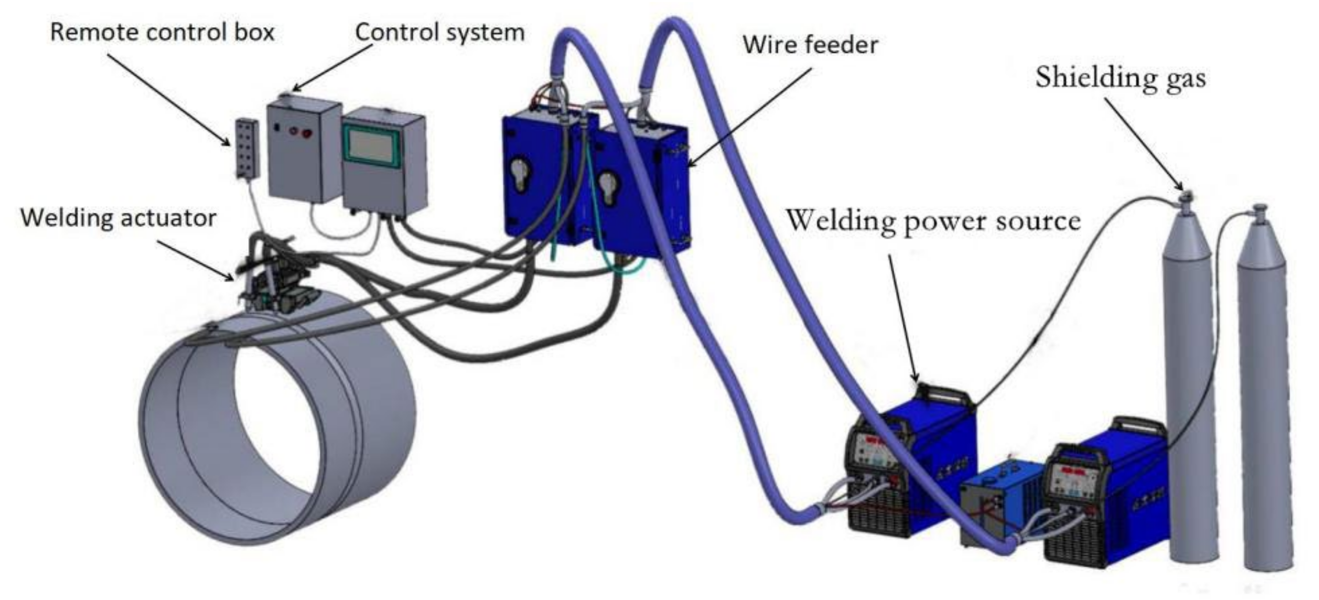
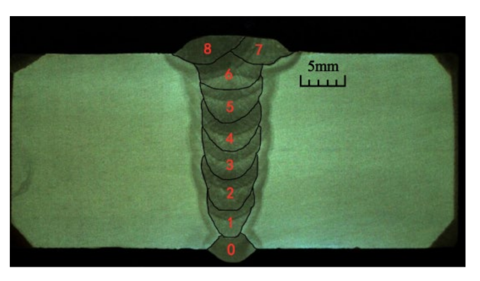
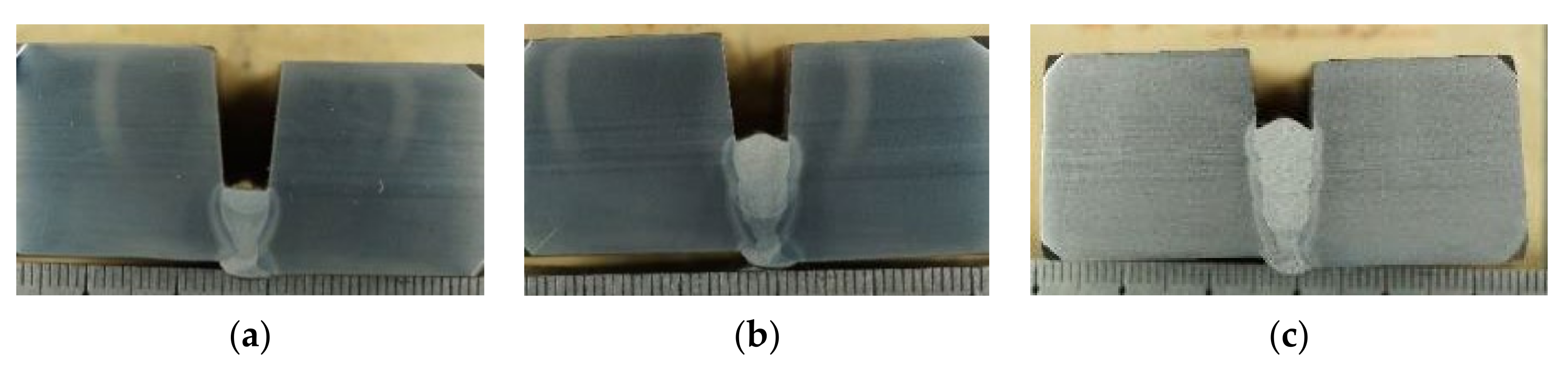
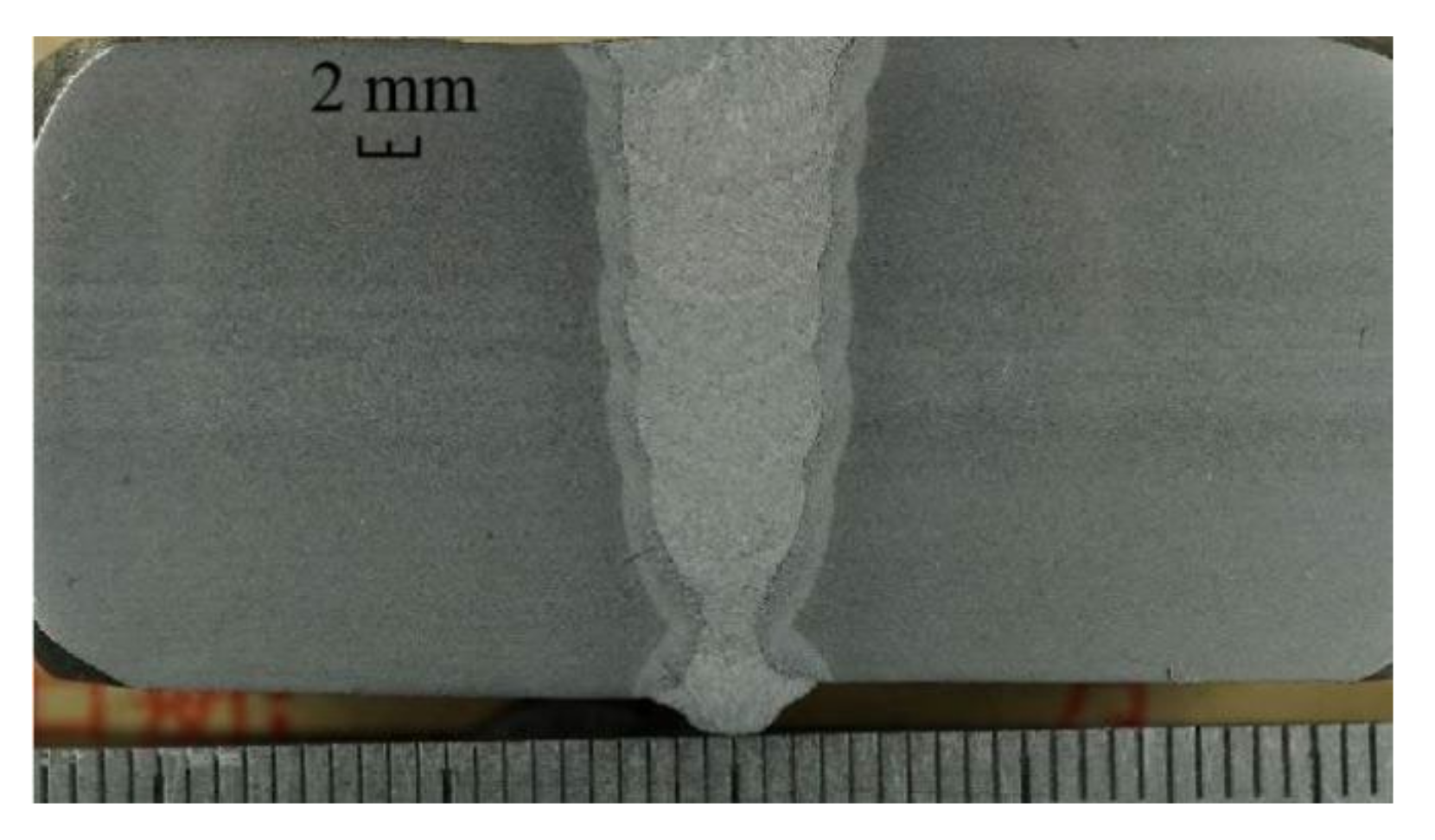
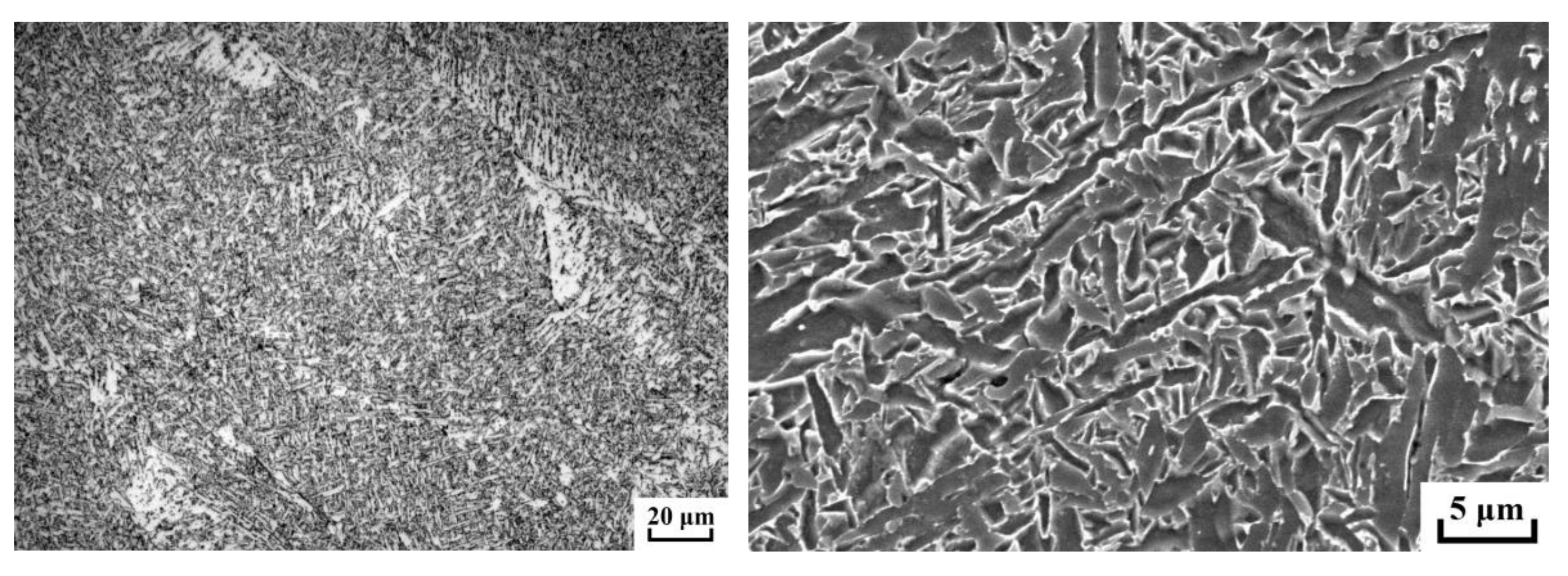
4. Welding Test
5. Conclusions
Author Contributions
Funding
Institutional Review Board Statement
Informed Consent Statement
Data Availability Statement
Conflicts of Interest
References
- Yin, T.; Jin, H.-C.; Zhao, H.; Zhang, Q. Effects of Ternary Shielding Gas on Weld Characteristics of All-Position Welding for Pipelines. Sci. Adv. Mater. 2021, 13, 2467–2474. [Google Scholar]
- Baek, D.; Moon, H.S.; Park, S.-H. Development of an automatic orbital welding system with robust weaving width control and a seam-tracking function for narrow grooves. Int. J. Adv. Manuf. Technol. 2017, 93, 767–777. [Google Scholar] [CrossRef]
- Fabry, C.; Pittner, A.; Rethmeier, M. Design of neural network arc sensor for gap width detection in automated narrow gap GMAW. Weld. World 2018, 62, 819–830. [Google Scholar] [CrossRef]
- Tsai, M.J.; Lee, H.-W.; Ann, N.-J. Machine vision based path planning for a robotic golf club head welding system. Robot. Comput. Integr. Manuf. 2011, 27, 843–849. [Google Scholar] [CrossRef]
- Kilic, Z.M.; Altintas, Y. Generalized mechanics and dynamics of metal cutting operations for unified simulations. Int. J. Mach. Tool Manuf. 2016, 104, 1–13. [Google Scholar] [CrossRef]
- Fridenfalk, M.; Bolmsjö, G. Design and validation of a universal 6D seam-tracking system in robotic welding using arc sensing. Adv. Robot. 2004, 18, 1–21. [Google Scholar] [CrossRef]
- Yan, S.J.; Ong, S.K.; Nee, A.Y.C. Optimal pass planning for robotic welding of large-dimension joints with deep grooves. Procedia CIRP 2016, 56, 188–192. [Google Scholar] [CrossRef]
- Mathivanan, A.; Devakumaran, K.; Kumar, A.S. Comparative Study on Mechanical and Metallurgical Properties of AA6061 Aluminum Alloy Sheet Weld by Pulsed Current and Dual Pulse Gas Metal Arc Welding Processes. Mater. Manuf. Process. 2014, 29, 941–947. [Google Scholar] [CrossRef]
- Sen, M.; Mukherjee, M.; Pal, T.K. Evaluation of Correlations between DP-GMAW Process Parameters and Bead Geometry. Weld. J. 2015, 94, 265–279. [Google Scholar]
- Rui, Z.; Xuanguo, W.; Fengbing, W. Off-line programming and simulation of multilayer-multipass welding for robot based on custom filling strategy. Weld. Technol. 2019, 48, 69–74. [Google Scholar]
- Praveen, P.; Yarlagadda, P.K.D.V.; Kang, M.J. Advancements in pulse gas metal arc welding. J. Mater. Process. Technol. 2005, 164–165, 1113–1119. [Google Scholar] [CrossRef]
- Kima, I.S.; Sona, J.S.; Parka, C.E.; Leea, C.W.; Prasadb, Y.K.D.V. A study on prediction of bead height in robotic arc welding using a neural network. J. Mater. Process. Technol. 2002, 130–131, 229–234. [Google Scholar] [CrossRef]
- Mathivanan, A.; Senthilkumar, A.; Devakumaran, K. Pulsed current and dual pulse gas metal arc welding of grade AISI: 310S austenitic stainless steel. Def. Technol. 2015, 11, 269–274. [Google Scholar] [CrossRef]
- Aviles-Viñas, J.F.; Rios-Cabrera, R.; Lopez-Juarez, I. On-line learning of welding bead geometry in industrial robots. Int. J. Adv. Manuf. Technol. 2016, 83, 217–231. [Google Scholar] [CrossRef]
- Jintian, Z.; Xinghua, W.; Tao, W. Theoretical analysis of forming control in single pass multi-layer arc additive manufacturing. J. Weld. 2019, 40, 63–67, 163–164. [Google Scholar]
- Yu, J.S.; Muller, P.C. An online Cartesian space obstacle avoidance scheme for robot arms. Math. Comput. Simul. 1996, 41, 627–637. [Google Scholar] [CrossRef]
- Rubio, F.; Valero, F.; Suner, J.L.; Mata, V.; Mata-Amela, V. A Comparison of Algorithms for Path Planning of Industrial Robots. In Proceedings of the EUCOMES 08; Springer: Dordrecht, The Netherlands, 2009; pp. 247–254. [Google Scholar] [CrossRef]
- Valero, F.; Mata, V.; Cuadrado, J.I. A formulation for path planning of manipulators in complex environments by using adja-cent configurations. Adv. Robot. 1997, 11, 33–55. [Google Scholar] [CrossRef]
- Kohrt, C.; Stamp, R.; Pipe, A.; Kiely, J.; Schiedermeier, G. An online robot trajectory planning and programming support system for industrial use. Robot. Comput. Manuf. 2012, 29, 71–79. [Google Scholar] [CrossRef]
- Chen, C.L.; Hu, S.S.; He, D.L.; Shen, J. An approach to the path planning of tube-sphere intersection welds with the robot dedicated to J-groove joints. Robot. Comput. Integr. Manuf. 2013, 29, 41–48. [Google Scholar] [CrossRef]
- Yan, Y. Study on the Coupling Law of Multi Parameter Arc Manufacturing; Huazhong University of Science and Technology: Wuhan, China, 2017. [Google Scholar]
- Jiqiang, H.; Shouxin, G.; Long, X.; Junfen, H.; Yingyu, C.; Yong, Z. Robot multi pass welding method for thick plate with groove deviation. J. Weld. 2020, 41, 60–66, 100. [Google Scholar]
- Fang, X.W.; Bai, H.; Yao, Y.F. Research on multi-bead overlapping process of wire and arc additive manufacturing based on cold metal transfer. J. Mech. Eng. 2020, 56, 141–147. [Google Scholar]
- Obeid, O.; Alfano, G.; Bahai, H.; Jouhara, H. Experimental and numerical thermo-mechanical analysis of welding in a lined pipe. J. Manuf. Process. 2018, 32, 857–872. [Google Scholar] [CrossRef]
- Kuryntsev, S. A Review: Laser Welding of Dissimilar Materials (Al/Fe, Al/Ti, Al/Cu)—Methods and Techniques. Microstruct. Prop. Mater. 2021, 15, 122. [Google Scholar] [CrossRef] [PubMed]
- Sun, X. Selection and application of welding consumables for X80 pipeline steel. Electr. Weld. Mach. 2019, 49, 1–9. [Google Scholar]


| Filler Layer Theory of the Height hi Methods | Equal Height Method (mm) | Equal Area Method (mm) |
|---|---|---|
| 1 | 2.82 | 3.44 |
| 2 | 2.82 | 3.11 |
| 3 | 2.82 | 2.85 |
| 4 | 2.82 | 2.65 |
| 5 | 2.82 | 2.49 |
| 6 | 2.82 | 2.35 |
| Calculated total layer height h | 16.92 | 16.89 |
| Filler Layer Theory of the Height hi Methods | Equal Height Method (mm) | Equal Area Method (mm) | A Lift Prediction Model with Upper and Lower Limits (mm) |
|---|---|---|---|
| 1 | 2.82 | 3.44 | 3.00 |
| 2 | 2.82 | 3.11 | 3.00 |
| 3 | 2.82 | 2.85 | 3.00 |
| 4 | 2.82 | 2.65 | 2.80 |
| 5 | 2.82 | 2.49 | 2.62 |
| 6 | 2.82 | 2.35 | 2.50 |
| Total layer height | 16.92 | 16.89 | 16.92 |
| Filler Layer Theory of the Height hi Correction Calculation | 1st Calculation (mm) | 1st Layer Height Correction Value (mm) | 2nd Calculation (mm) | 2nd Layer Height Correction Value (mm) | 3rd Calculation (mm) | Final Result (mm) |
|---|---|---|---|---|---|---|
| h | 16.9 | 10.9 | 7.9 | 16.9 | ||
| n_middle | 6 | 4 | 3 | 6 | ||
| 1st layer | 3.44 | 3.00 | 3.00 | |||
| 2nd layer | 3.11 | 3.00 | 3.00 | |||
| 3rd layer | 2.85 | 3.02 | 3.00 | 3.00 | ||
| 4th layer | 2.65 | 2.80 | 2.80 | 2.80 | ||
| 5th layer | 2.49 | 2.62 | 2.62 | 2.62 | ||
| 6th layer | 2.35 | 2.47 | 2.48 | 2.50 | ||
| Total layer height | 16.92 |
| Material | C | Si | Mn | P | S | Mo | Ni+Cr+Cu | Nb+V+Ti | Ceq |
|---|---|---|---|---|---|---|---|---|---|
| X80 | 0.05~0.07 | 0.25 | ≤1.80 | 0.01 | 0.001 | ≤0.35 | ≤0.50 | ≤0.15 | 0.42~0.44 |
| Element | C | Si | Mn | P | S | Cr | Mo | Ni | V | Cu | Ti | Al |
|---|---|---|---|---|---|---|---|---|---|---|---|---|
| Filler metal | 0.05 | 0.69 | 1.53 | 0.004 | 0.006 | 0.020 | 0.004 | 0.89 | <0.001 | 0.110 | 0.060 | 0.003 |
| Layers | Welding Parameters | 3 O’clock | 4 O’clock | 5 O’clock | 6 O’clock |
|---|---|---|---|---|---|
| 1st layer | Welding speed (cm/min) | 59.9 | 55.1 | 55.5 | 52.1 |
| Current (A) | 219.2 | 196.7 | 210.4 | 194.4 | |
| Voltage (V) | 25.2 | 25.1 | 24.7 | 24.8 | |
| Swing width (mm) | 0 | 0 | 0 | 0 | |
| 2nd layer | Welding speed (cm/min) | 45.5 | 42.8 | 41.8 | 38.7 |
| Current (A) | 207.9 | 198.4 | 188.2 | 185.8 | |
| Voltage (V) | 25.7 | 25.2 | 24.8 | 23.8 | |
| Swing width (mm) | 1.2 | 1.3 | 1.7 | 1.7 | |
| Swing time (ms) | 120 | 120 | 120 | 120 | |
| Swing speed (mm/s) | 10 | 10.8 | 14.2 | 14.2 | |
| Edge dwell time (ms) | 40 | 60 | 80 | 80 | |
| 3rd layer | Welding speed (cm/min) | 45.3 | 42.5 | 38.9 | 39 |
| Current (A) | 193.1 | 194.1 | 180.9 | 176.5 | |
| Voltage (V) | 25.5 | 25.2 | 23.8 | 24.5 | |
| Swing width (mm) | 1.2 | 1.3 | 1.7 | 1.7 | |
| Swing time (ms) | 120 | 120 | 120 | 120 | |
| Swing speed (mm/s) | 10 | 10.8 | 14.2 | 14.2 | |
| Edge dwell time (ms) | 40 | 60 | 80 | 80 | |
| 4th layer | Welding speed (cm/min) | 47.7 | 43.8 | 37.7 | 37.1 |
| Current (A) | 203 | 202.7 | 187.1 | 176 | |
| Voltage (V) | 25.3 | 24.4 | 23.8 | 24 | |
| Swing width (mm) | 1.8 | 2 | 2.4 | 2.4 | |
| Swing time (ms) | 120 | 120 | 120 | 120 | |
| Swing speed (mm/s) | 15 | 16.7 | 20 | 20 | |
| Edge dwell time (ms) | 40 | 60 | 80 | 80 | |
| 5th layer | Welding speed (cm/min) | 47.3 | 43.6 | 41.7 | 36.9 |
| Current (A) | 199.2 | 184 | 177.5 | 189.1 | |
| Voltage (V) | 25.3 | 24.8 | 24.3 | 23.8 | |
| Swing width (mm) | 1.8 | 2 | 2.4 | 2.4 | |
| Swing time (ms) | 120 | 120 | 120 | 120 | |
| Swing speed (mm/s) | 15 | 16.7 | 20 | 20 | |
| Edge dwell time (ms) | 40 | 60 | 80 | 80 | |
| 6th layer | Welding speed (cm/min) | 44 | 43.5 | 43.9 | 41.6 |
| Current (A) | 230 | 229.4 | 200.3 | 170.8 | |
| Voltage (V) | 25.4 | 25.2 | 24.9 | 24 | |
| Swing width (mm) | 2.4 | 2.6 | 3 | 3 | |
| Swing time (ms) | 150 | 150 | 150 | 150 | |
| Swing speed (mm/s) | 16 | 17.3 | 20 | 22 | |
| Edge dwell time (ms) | 40 | 60 | 80 | 80 |
Publisher’s Note: MDPI stays neutral with regard to jurisdictional claims in published maps and institutional affiliations. |
© 2022 by the authors. Licensee MDPI, Basel, Switzerland. This article is an open access article distributed under the terms and conditions of the Creative Commons Attribution (CC BY) license (https://creativecommons.org/licenses/by/4.0/).
Share and Cite
Yin, T.; Wang, J.; Zhao, H.; Zhou, L.; Xue, Z.; Wang, H. Research on Filling Strategy of Pipeline Multi-Layer Welding for Compound Narrow Gap Groove. Materials 2022, 15, 5967. https://doi.org/10.3390/ma15175967
Yin T, Wang J, Zhao H, Zhou L, Xue Z, Wang H. Research on Filling Strategy of Pipeline Multi-Layer Welding for Compound Narrow Gap Groove. Materials. 2022; 15(17):5967. https://doi.org/10.3390/ma15175967
Chicago/Turabian StyleYin, Tie, Jinpeng Wang, Hong Zhao, Lun Zhou, Zenghuan Xue, and Hehe Wang. 2022. "Research on Filling Strategy of Pipeline Multi-Layer Welding for Compound Narrow Gap Groove" Materials 15, no. 17: 5967. https://doi.org/10.3390/ma15175967