
Design and Mechanical Characterisation of a Large Truss Structure for Continuous Manufacturing in Space
Abstract
:1. Introduction
2. About Large Structures in Space Manufacturing Methods
2.1. Structural Design Constraints
- (1)
- Ambient temperature suitability of raw materials, which are subject to large differences in temperature under track conditions, with a temperature variation range of ±150 °C. The selected raw materials should be adapted to the changes in space temperature.
- (2)
- Packing density of upstream replenishment material. Upstream replenishment materials should be consistent in configuration and size as much as possible to maximize the utilization of the volume of the material in the box, that is, to obtain a greater packing density.
- (3)
- Types of materials that make up the structure. The less variety of materials required for the truss structure, the fewer external resources are required for in-space fabrication and the simpler the construction process.
- (4)
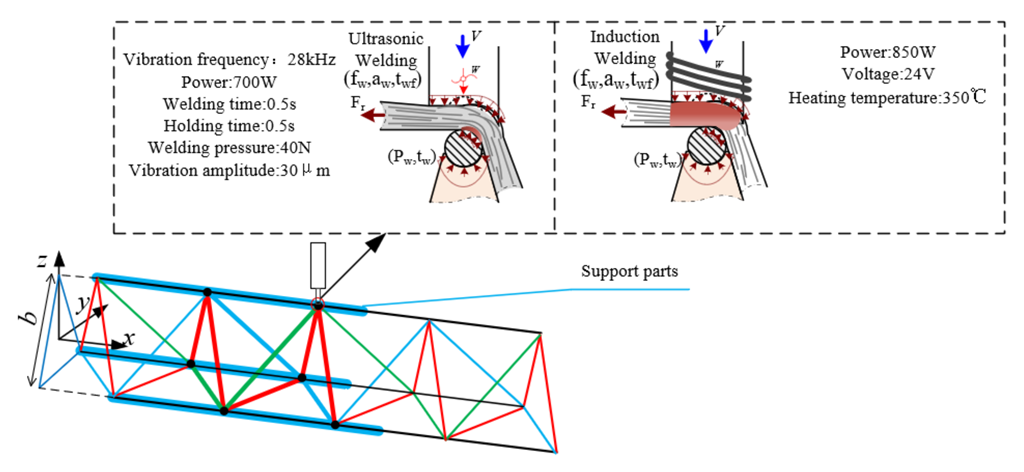
- Applicability of the joining process between the elements. The in-space connection between elements should be low power consumption, low force, low thermal disturbance and low dependence on the space environment. No additional connectors are needed to minimize the consumption of space resources in the in-space connection process.
2.2. Raw Material Selection
2.3. In-Space Connection Method
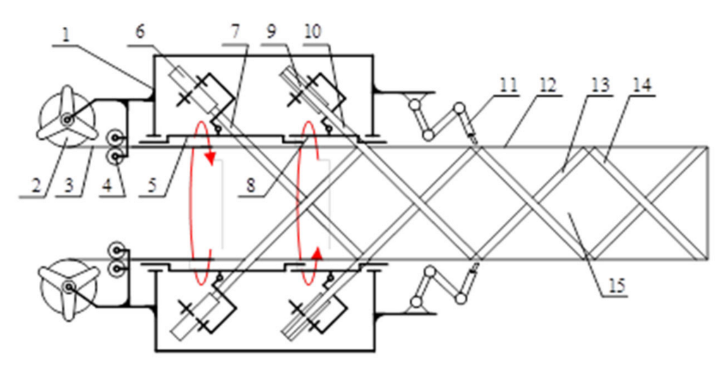
2.4. In-Space Construction Program for Large Structures
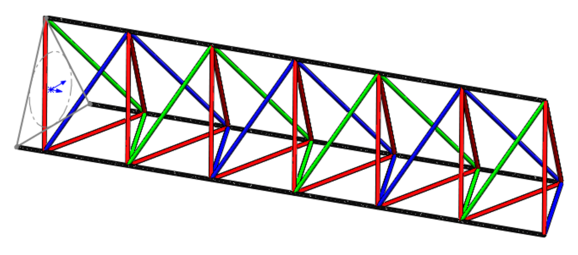
3. Design and Mechanical Modelling of Continuously Buildable 1D Truss Configurations
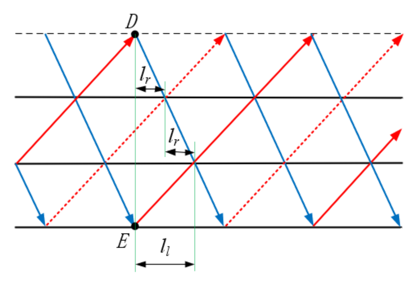
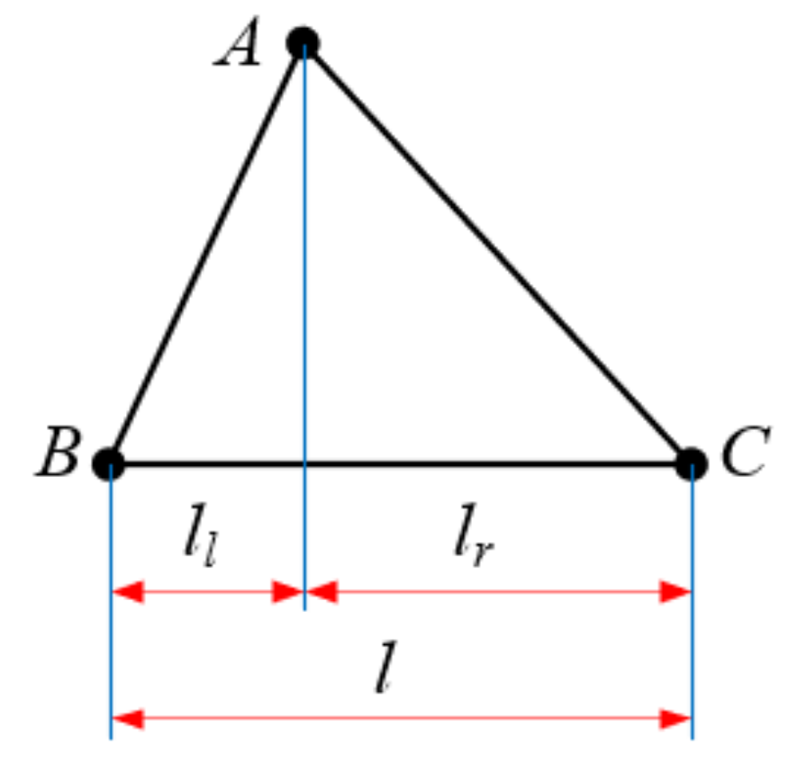
3.1. Analysis of the Necessary Conditions for the Configuration of a One-Dimensional Truss That Can Be Built Continuously
3.2. Modelling of Mechanical Properties of Continuously Buildable Truss Structures
- (1)
- Analysis of the mechanical properties of the truss
- (2)
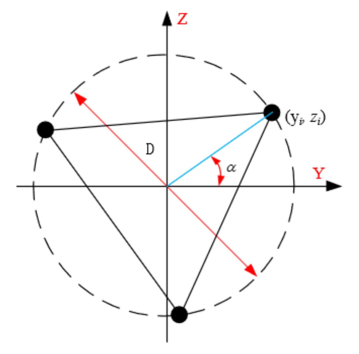
- Moment of inertia of the truss section
- (3)
- Truss vibration frequency
- (4)
- Static stiffness
4. Simulation of the Mechanical Properties of a Continuously Buildable Truss Structure
4.1. Material Influence on Truss Fundamental Frequency
- (1)
- Poisson’s ratio
- (2)
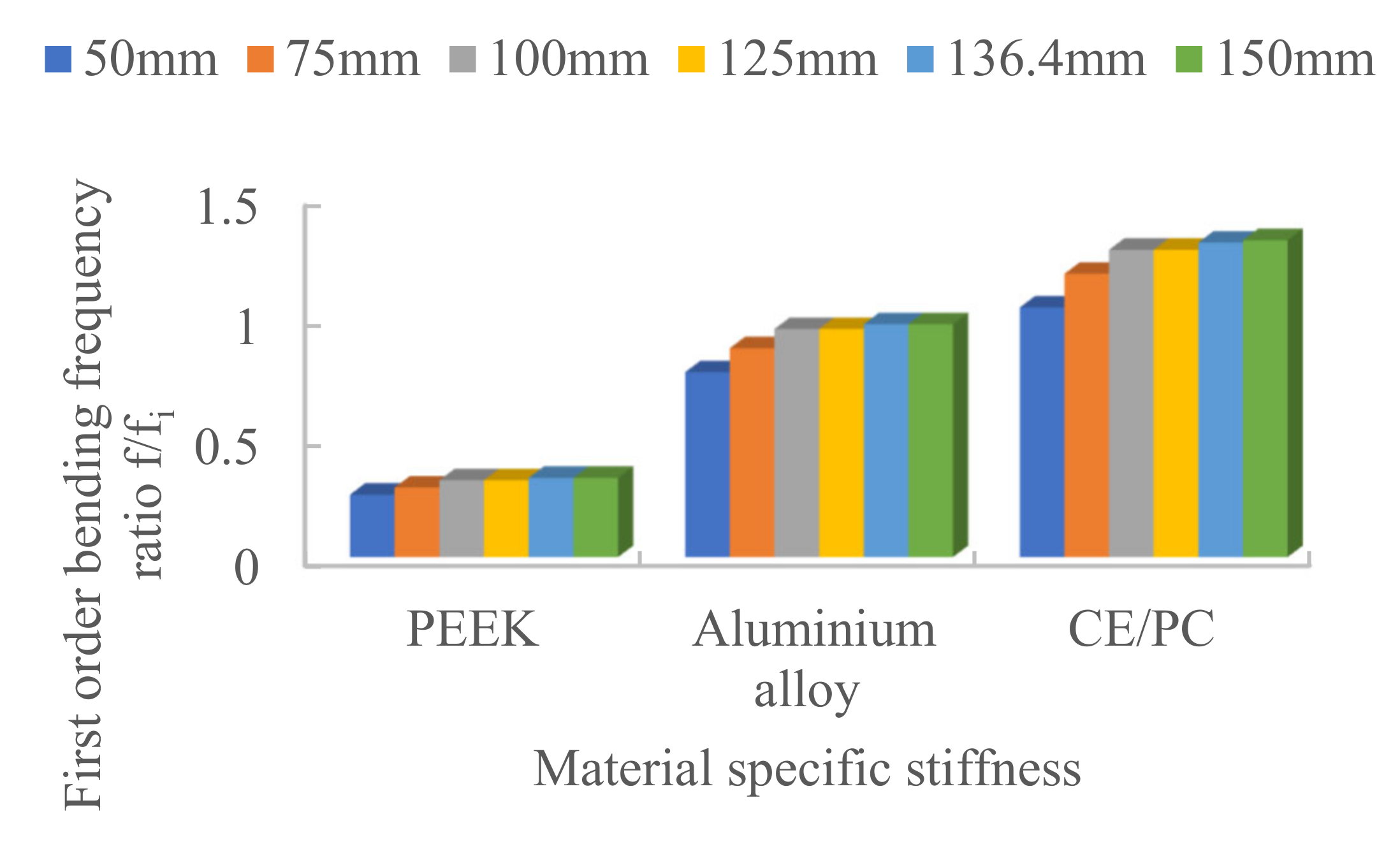
- Specific stiffness
4.2. Influence of Truss Configuration Parameters on Mechanical Properties
- (1)
- Radius of truss rod section
- (2)
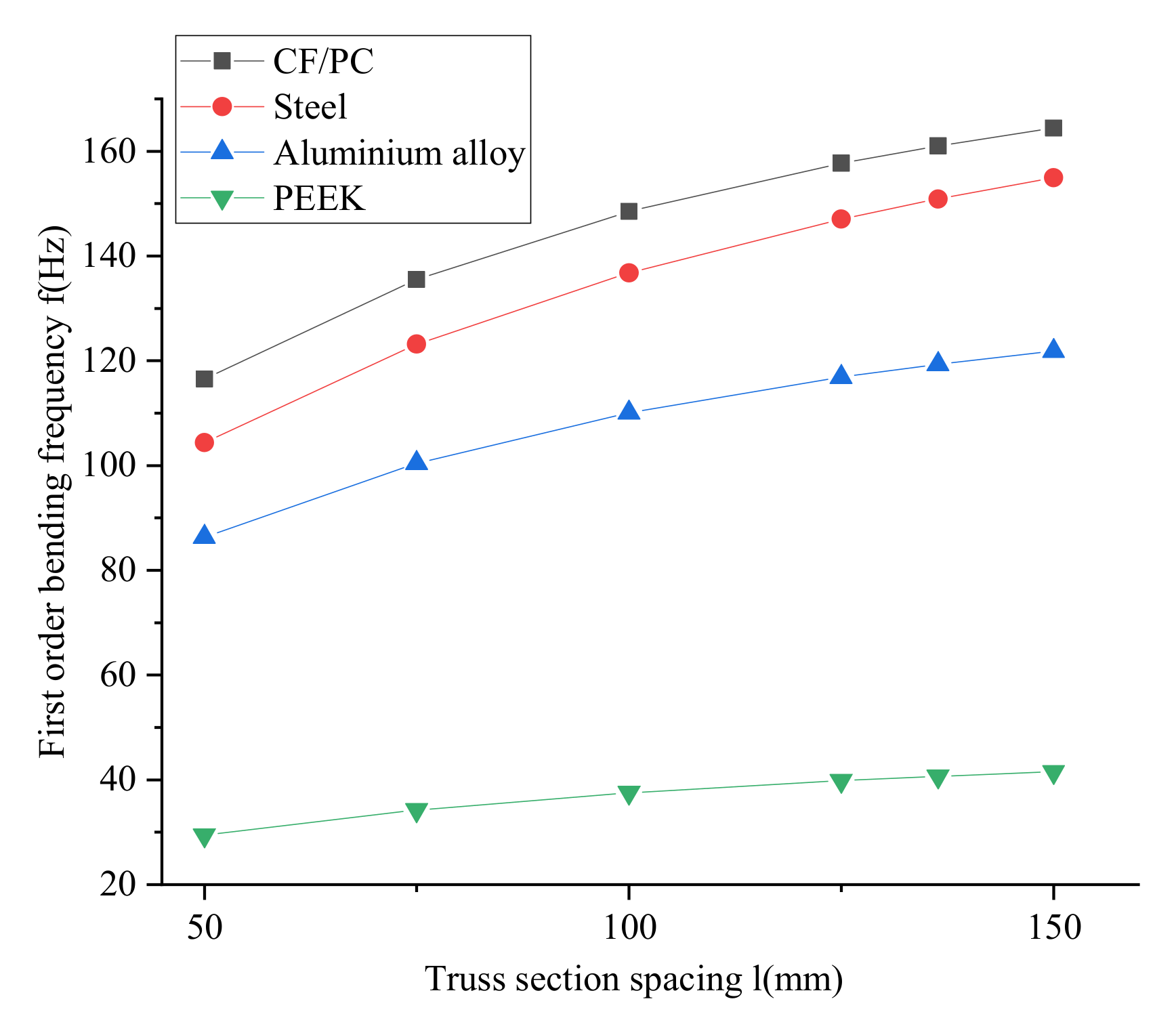
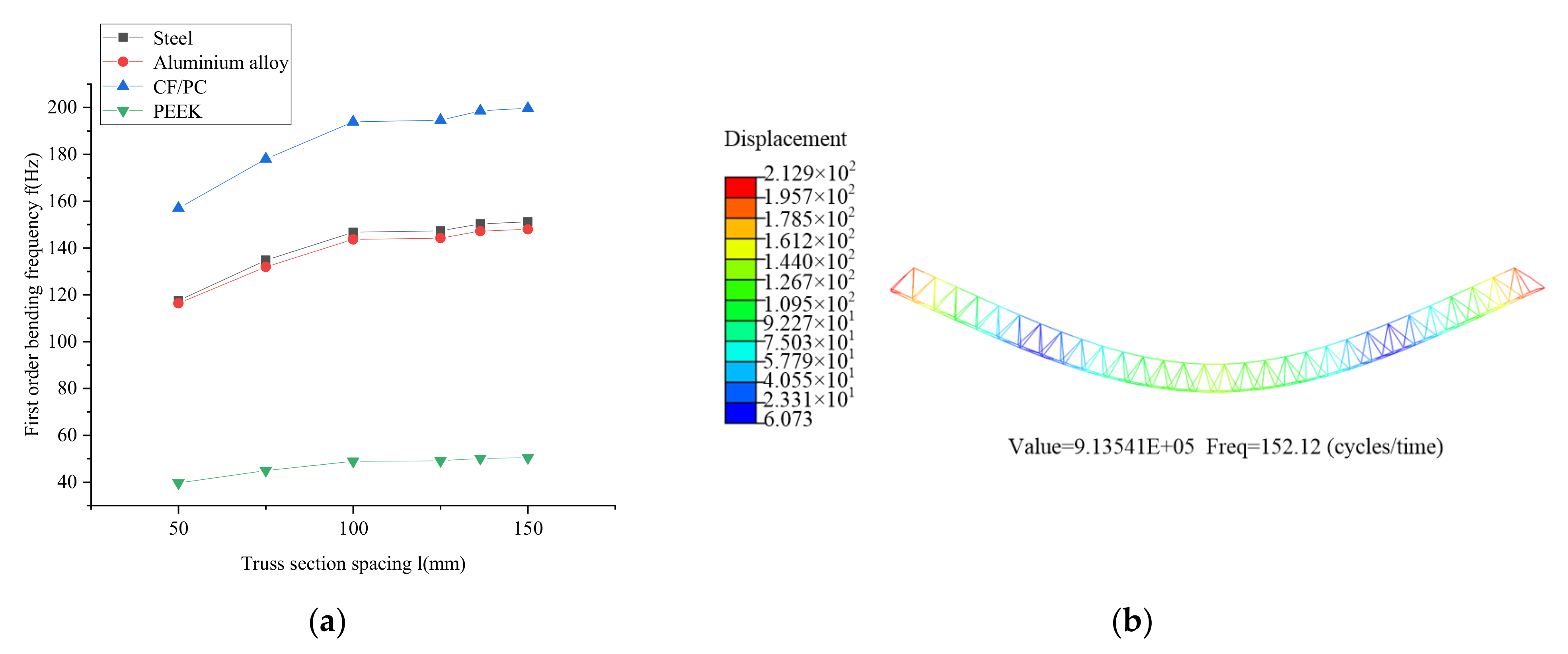
- Section spacing
- (3)
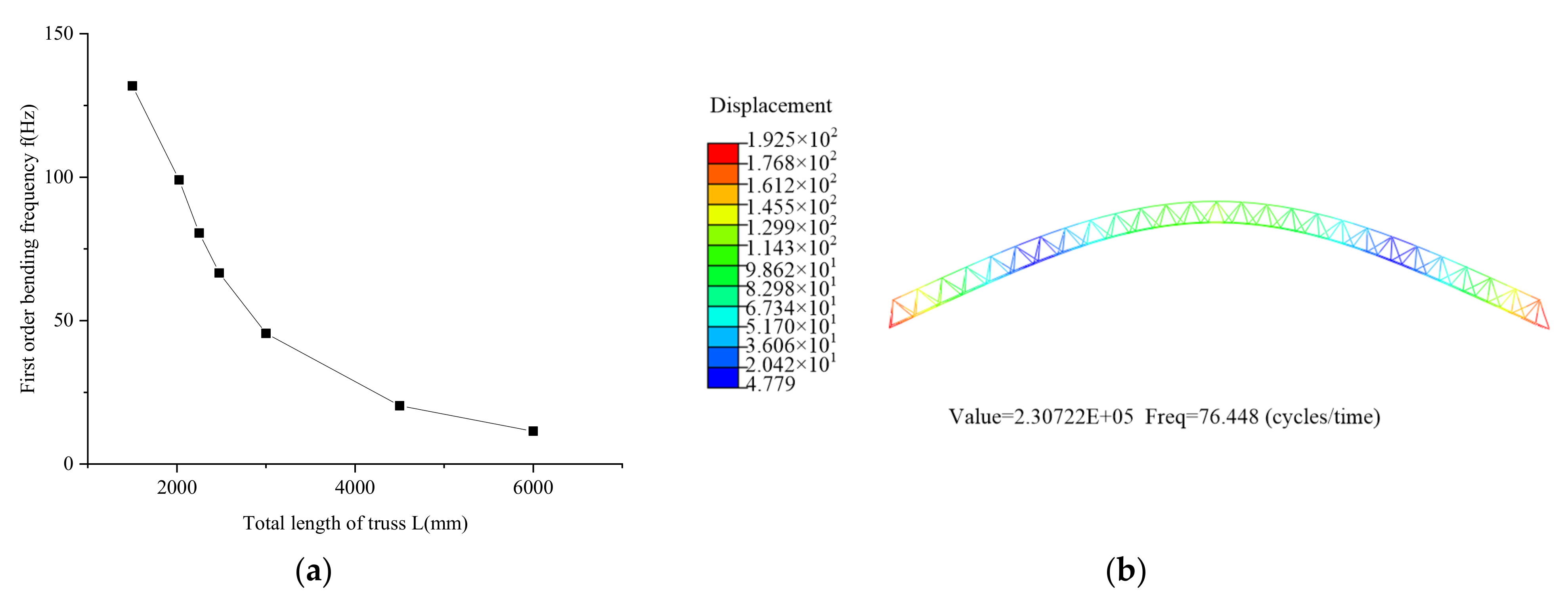
- Total length of truss
5. Experimental Validation and Analysis
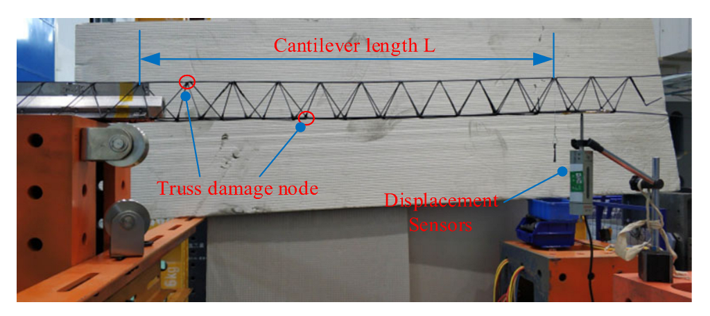
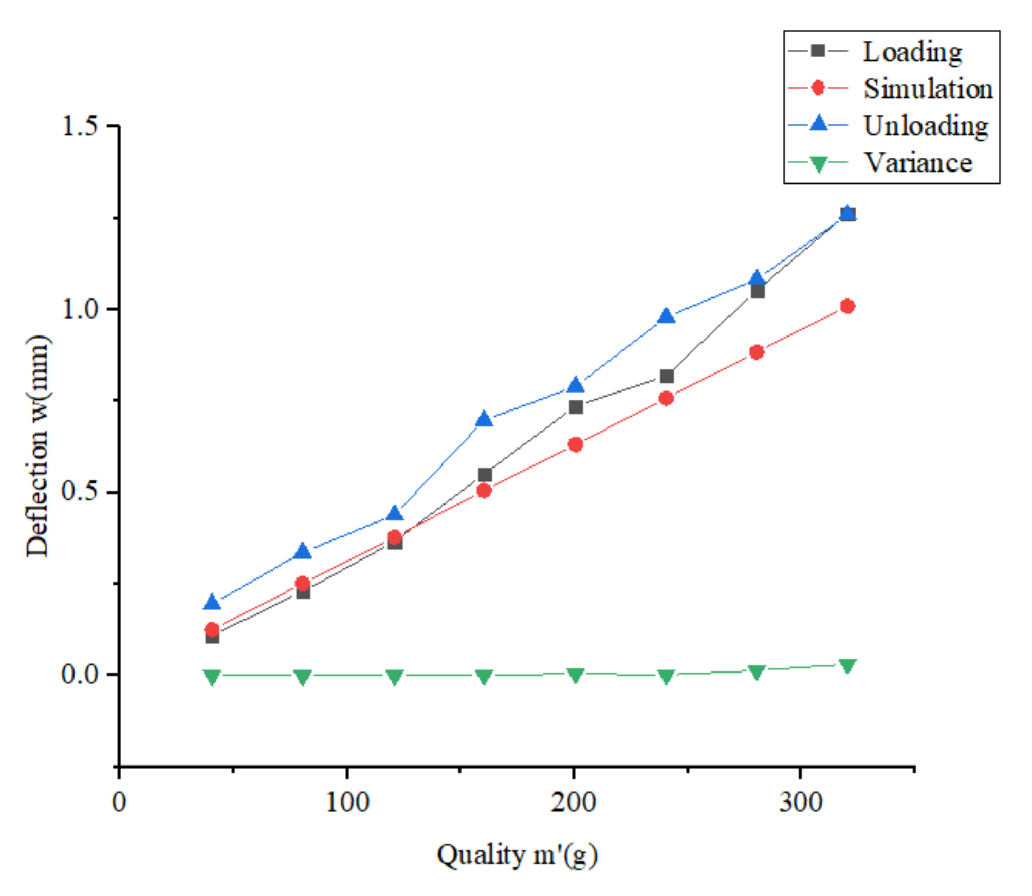
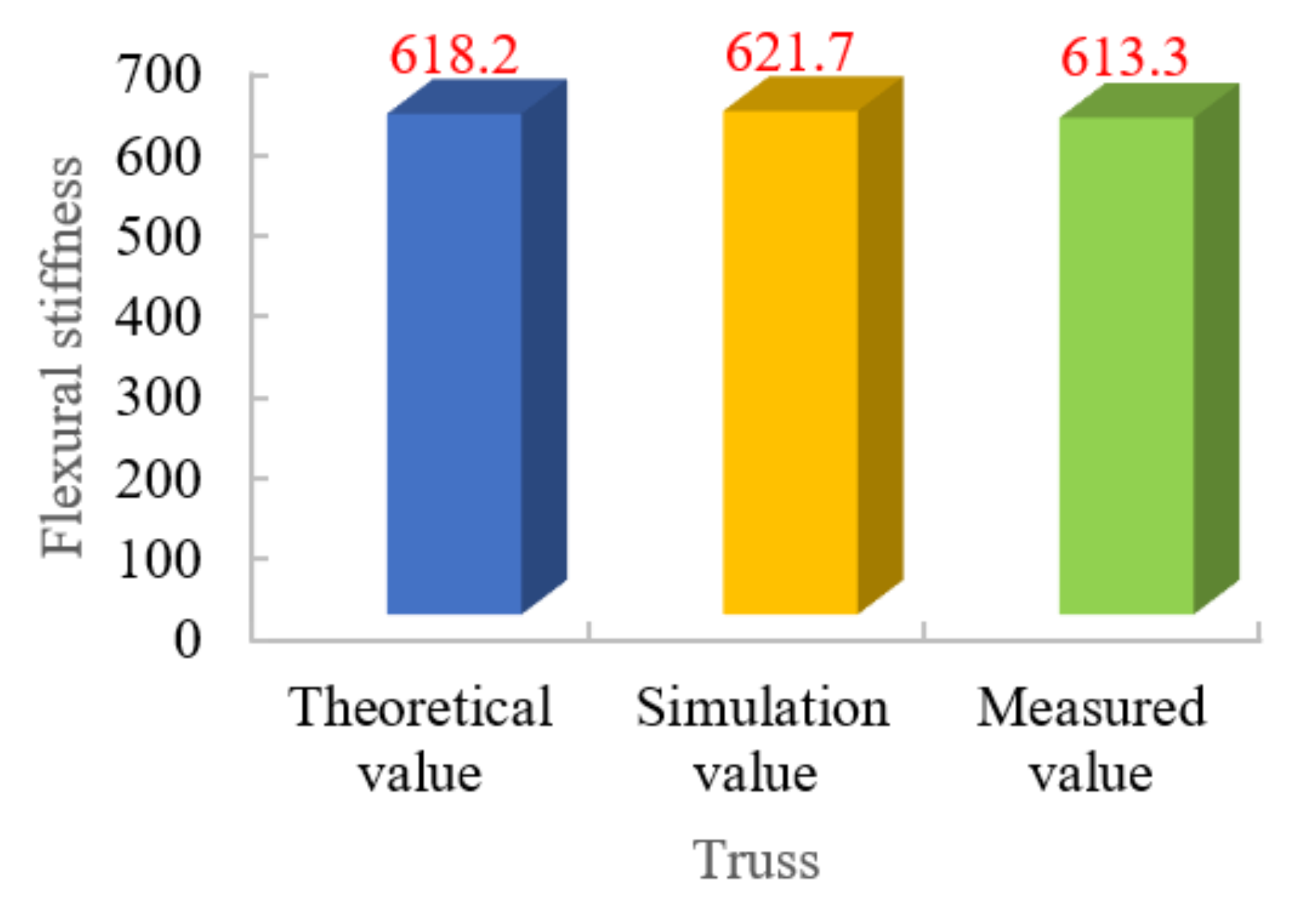
5.1. Truss Stiffness Test
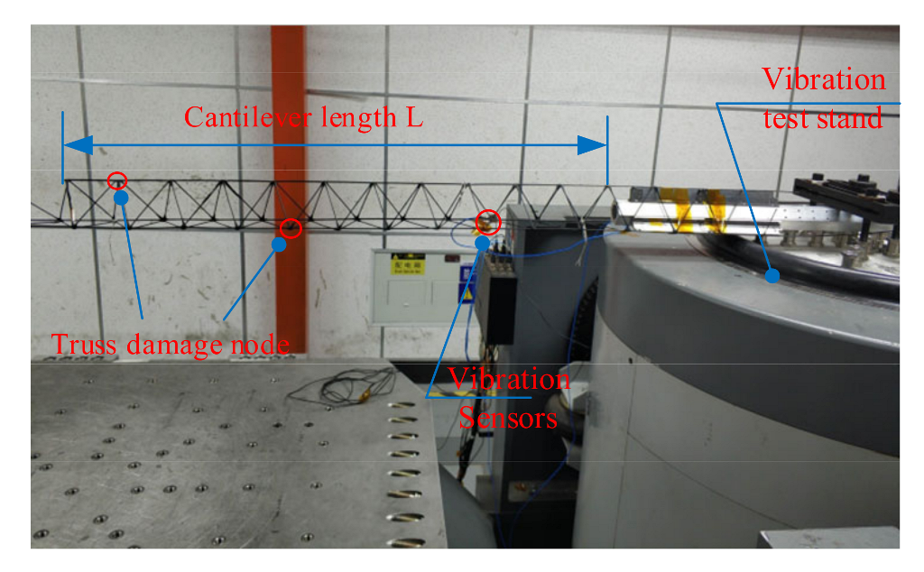
5.2. Truss Vibration Characteristics Test
6. Conclusions
- (1)
- The truss construction system can be used to prepare continuous truss samples so that the carbon fiber-reinforced auxiliary materials can be manufactured continuously without interruptions to improve their stiffness and the truss construction efficiency.
- (2)
- The fundamental frequency of the truss is independent of Poisson’s ratio of truss material and section diameter d. The fundamental frequency of the joist is related to the overall length L, section spacing l and material-specific stiffness of the beam.
- (3)
- The measured flexural stiffness is 5% smaller than the theoretical value by the static stiffness test and joist vibration fundamental frequency test. The error between the measured and simulated values of the first two vibration frequencies is 5%.
- (4)
- The error may be caused by the fact that the elastic modulus of the material is not directly measured, resulting in the actual elastic modulus being smaller than the reference value; defects in the prepared truss samples, such as the breakage of some fibers or insufficient straightness of the rod frame; defects in the nodes of the truss samples, such as some nodes failing to connect effectively.
Author Contributions
Funding
Institutional Review Board Statement
Informed Consent Statement
Data Availability Statement
Conflicts of Interest
References
- Fallah, N.; Vaez, S.R.H.; Mohammadzadeh, A. Multi-damage identification of large-scale truss structures using a two-step approach. J. Build. Eng. 2018, 19, 494–505. [Google Scholar] [CrossRef]
- Garoli, D.; Rodriguez De Marcos, L.V.; Larruquert, J.I.; Corso, A.J.; Proietti Zaccaria, R.; Pelizzo, M.G. Mirrors for Space Telescopes: Degradation Issues. Appl. Sci. 2020, 10, 7538. [Google Scholar] [CrossRef]
- Kazemzadeh Azad, S.; Aminbakhsh, S. High-dimensional optimization of large-scale steel truss structures using guided stochastic search. Structures 2021, 33, 1439–1456. [Google Scholar] [CrossRef]
- Kaveh, A.; Zakian, P. Improved GWO algorithm for optimal design of truss structures. Eng. Comput. 2017, 34, 685–707. [Google Scholar] [CrossRef]
- Xu, T.; Tang, S.; Liu, C.; Li, Z.; Fan, H.; Ma, S. Obtaining large-size pyramidal lattice cell structures by pulse wire arc additive manufacturing. Mater. Des. 2020, 187, 108401. [Google Scholar] [CrossRef]
- Cai, Q.; He, L.; Xie, Y.; Feng, R.; Ma, J. Simple and effective strategies to generate diverse designs for truss structures. Structures 2021, 32, 268–278. [Google Scholar] [CrossRef]
- Li, X.; Pan, J.; Zhou, X. Impact Resistance Analysis and Optimization of Variant Truss Beam Structure Based on Material Properties. Materials 2021, 14, 5847. [Google Scholar] [CrossRef] [PubMed]
- Bernardo, L.F.A.; Teixeira, M.M.; De Domenico, D.; Gama, J.M.R. Improved Equations for the Torsional Strength of Reinforced Concrete Beams for Codes of Practice Based on the Space Truss Analogy. Materials 2022, 15, 3827. [Google Scholar] [CrossRef] [PubMed]
- Liu, C.; Xu, K.; Zhang, Y.; Hu, H.; Tao, X.; Zhu, Z.; Deng, W.; Zhang, X. Design and Fabrication of Extremely Lightweight Truss-Structured Metal Mirrors. J. Mater. 2022, 15, 4562. [Google Scholar] [CrossRef] [PubMed]
- Zhang, L.; Deng, R.; Ning, N.; Fan, J.; Wang, W.; Song, K. Study on Remote Field Eddy Current Testing Technology for Crack-like Defects in Long Truss Structure of Aircraft. J. Mater. 2022, 15, 5093. [Google Scholar] [CrossRef] [PubMed]
- McInnes, C.R. Near Earth asteroid resource utilisation for large in-orbit reflectors. Space Policy 2016, 37, 62–64. [Google Scholar] [CrossRef]
- Mikulas, M.M. Truss Performance and Packaging Metrics. AIP Conf. Proc. 2006, 813, 1000–1009. [Google Scholar]
- Hoyt, R.; Cushing, J.; Slostad, J.S.J.B. Final Report NNX12AR13G-FINAL. In Process for On-Orbit Construction of Kilometer-Scale Apertures; Tethers Unlimited Inc.: Seattle, WA, USA, 2013. [Google Scholar]
- Levedahl, B.; Hoyt, R.P.; Silagy, T.; Gorges, J.; Britton, N.; Slostad, J. Trusselator™ Technology for In-Situ Fabrication of Solar Array Support Structures. In Proceedings of the 2018 AIAA Spacecraft Structures Conference, Kissimmee, FL, USA, 8–12 January 2018. [Google Scholar]
- Bhundiya, H.G.; Royer, F.; Cordero, Z. Engineering Framework for Assessing Materials and Processes for In-Space Manufacturing. J. Mater. Eng. Perform. 2022, 31, 6045–6059. [Google Scholar] [CrossRef]
- Liu, S.; Li, Y.; Li, N. A novel free-hanging 3D printing method for continuous carbon fiber reinforced thermoplastic lattice truss core structures. Mater. Des. 2018, 137, 235–244. [Google Scholar] [CrossRef]
- Kim, T.-H.; Suh, J.-E.; Han, J.-H. Deployable truss structure with flat-form storability using scissor-like elements. Mech. Mach. Theory 2021, 159, 104–255. [Google Scholar] [CrossRef]
- Dai, L.; Xiao, R. Optimal design and analysis of deployable antenna truss structure based on dynamic characteristics restraints. Aerosp. Sci. Technol. 2020, 106, 106086. [Google Scholar] [CrossRef]
- Suh, J.-E.; Jeong, S.-Y.; Han, J.-H. A two-dimensional modular deployable truss structure with bistability. J. Intell. Mater. Syst. Struct. 2018, 30, 335–350. [Google Scholar] [CrossRef]
- Li, W.J.; Wu, Y.S.; Wei, Q.S.; Wei, C. Multifield Coupling Dynamics of Large Truss Structure for Space Applications. In Proceedings of the 2019 IEEE 10th International Conference on Mechanical and Aerospace Engineering (ICMAE), Belgium, Brussels, 22–25 July 2019; pp. 52–56. [Google Scholar]
- Siriguleng, B.; Zhang, W.; Liu, T.; Liu, Y.Z. Vibration modal experiments and modal interactions of a large space deployable antenna with carbon fiber material and ring-truss structure. J. Eng. Struct. 2020, 207, 109932. [Google Scholar] [CrossRef]
- Martineau, L.; Chabert, F.; Bernhart, G.; Djilali, T. Mechanical behavior of amorphous PEEK in the rubbery state. In Proceedings of the ECCM17-17th European Conference on Composite Materials, Munich, Germany, 26–30 June 2016. [Google Scholar]
- Mohan, S.; Dinesha, P.; Iyengar, S.A. Modeling and analysis of a solar minichannel flat plate collector system and optimization of operating conditions using particle swarms. Therm. Sci. Eng. Prog. 2021, 22, 100855. [Google Scholar] [CrossRef]
- Murphey, T.; Hinkle, J. Some performance trends in hierarchical truss structures. In Proceedings of the 44th AIAA/ASME/ASCE/AHS/ASC Structures, Structural Dynamics, and Materials Conference, Norfolk, VA, USA, 7 April 2003; p. 1903. [Google Scholar]


| Materials | Glass State Transition Temperature or Melting Point (°C) | Thermal Conductivity (W/m·°C) | Low Temperature Environment Applicability | Manufacturing Process |
|---|---|---|---|---|
| PEEK | 143 | 0.29 | applicable | Hot Melt Molding |
| PC/CF | 144 | 0.2 | applicable | Hot Melt Molding |
| structural steel (45#) | 1500 | 48.9 | no applicable | Extrusion molding |
| aluminum alloy (7075) | 650 | 228 | no applicable | Extrusion molding |
| First-Order | Second-Order | Third-Order | Fourth-Order | |
|---|---|---|---|---|
| Test Value | 72.4 | 74.5 | 200 | 200 |
| Simulation value | 76.44 | 76.45 | 203.41 | 203.49 |
| Error | 4.14% | 2.62% | 1.71% | 1.75% |
Publisher’s Note: MDPI stays neutral with regard to jurisdictional claims in published maps and institutional affiliations. |
© 2022 by the authors. Licensee MDPI, Basel, Switzerland. This article is an open access article distributed under the terms and conditions of the Creative Commons Attribution (CC BY) license (https://creativecommons.org/licenses/by/4.0/).
Share and Cite
Li, P.; Ning, H.; Yan, J.; Xu, B.; Li, H. Design and Mechanical Characterisation of a Large Truss Structure for Continuous Manufacturing in Space. Materials 2022, 15, 6025. https://doi.org/10.3390/ma15176025
Li P, Ning H, Yan J, Xu B, Li H. Design and Mechanical Characterisation of a Large Truss Structure for Continuous Manufacturing in Space. Materials. 2022; 15(17):6025. https://doi.org/10.3390/ma15176025
Chicago/Turabian StyleLi, Peng, Hongyang Ning, Jiayong Yan, Bo Xu, and Hongjian Li. 2022. "Design and Mechanical Characterisation of a Large Truss Structure for Continuous Manufacturing in Space" Materials 15, no. 17: 6025. https://doi.org/10.3390/ma15176025