

Wear Performance of Circular Shim against Cam in Engine Bench Test


Abstract
:1. Introduction
2. Experimental
3. Results and Discussion
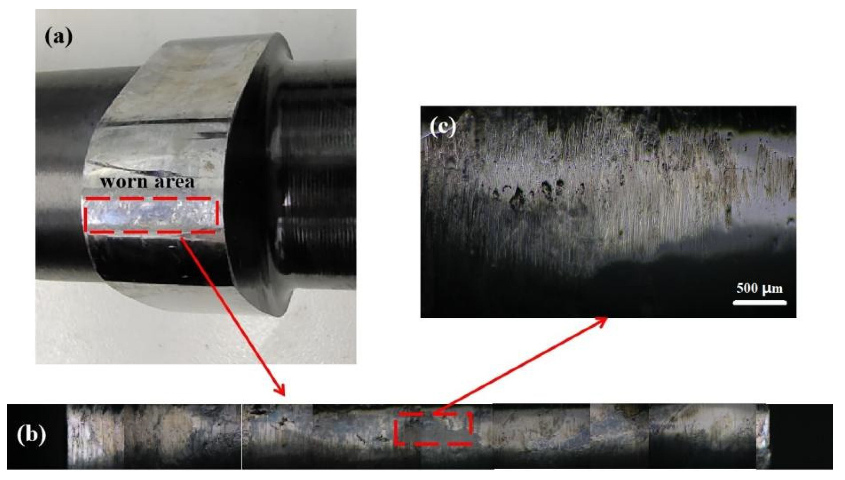
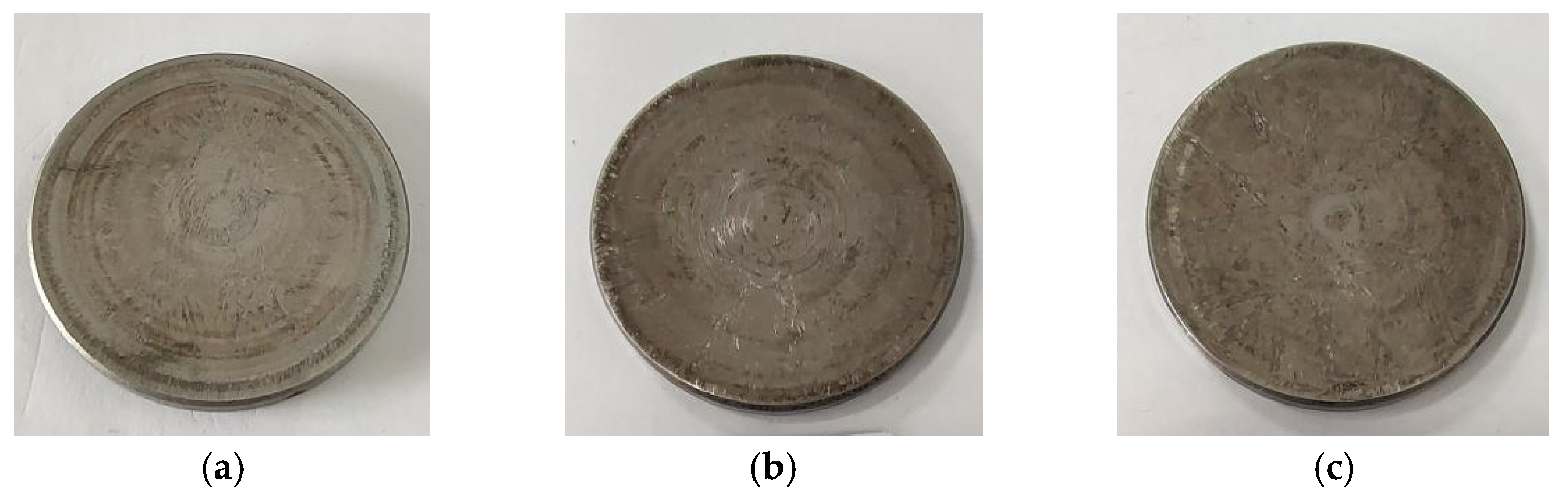
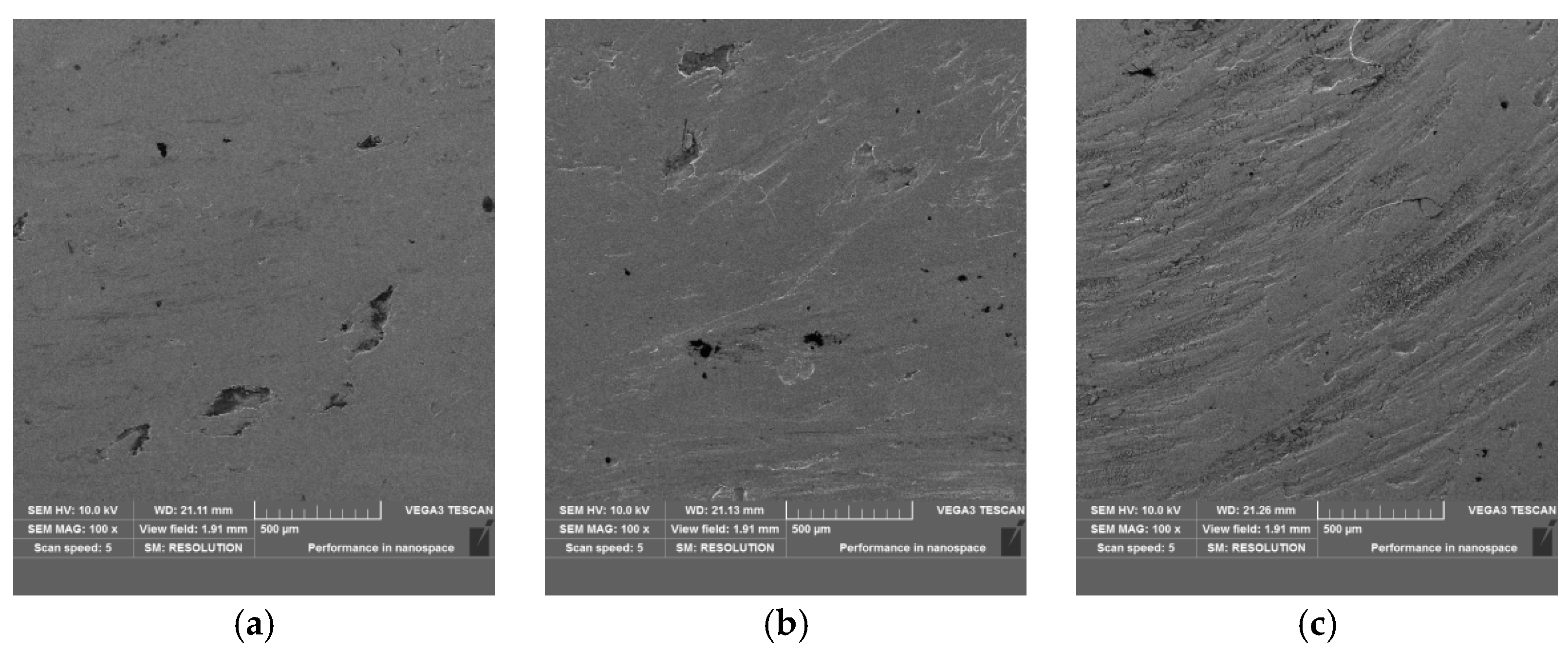
3.1. Worn Surface
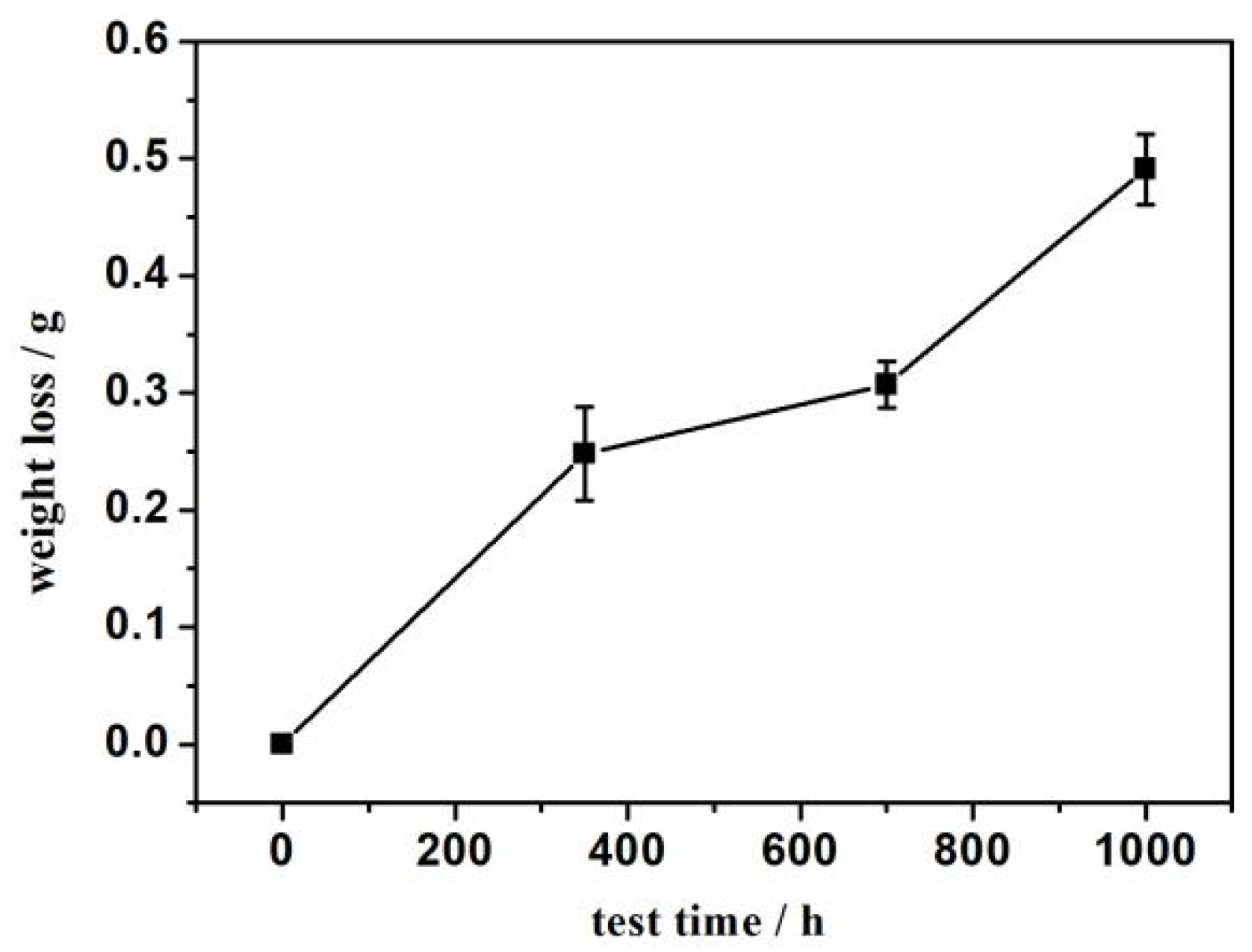
3.2. Weight Loss
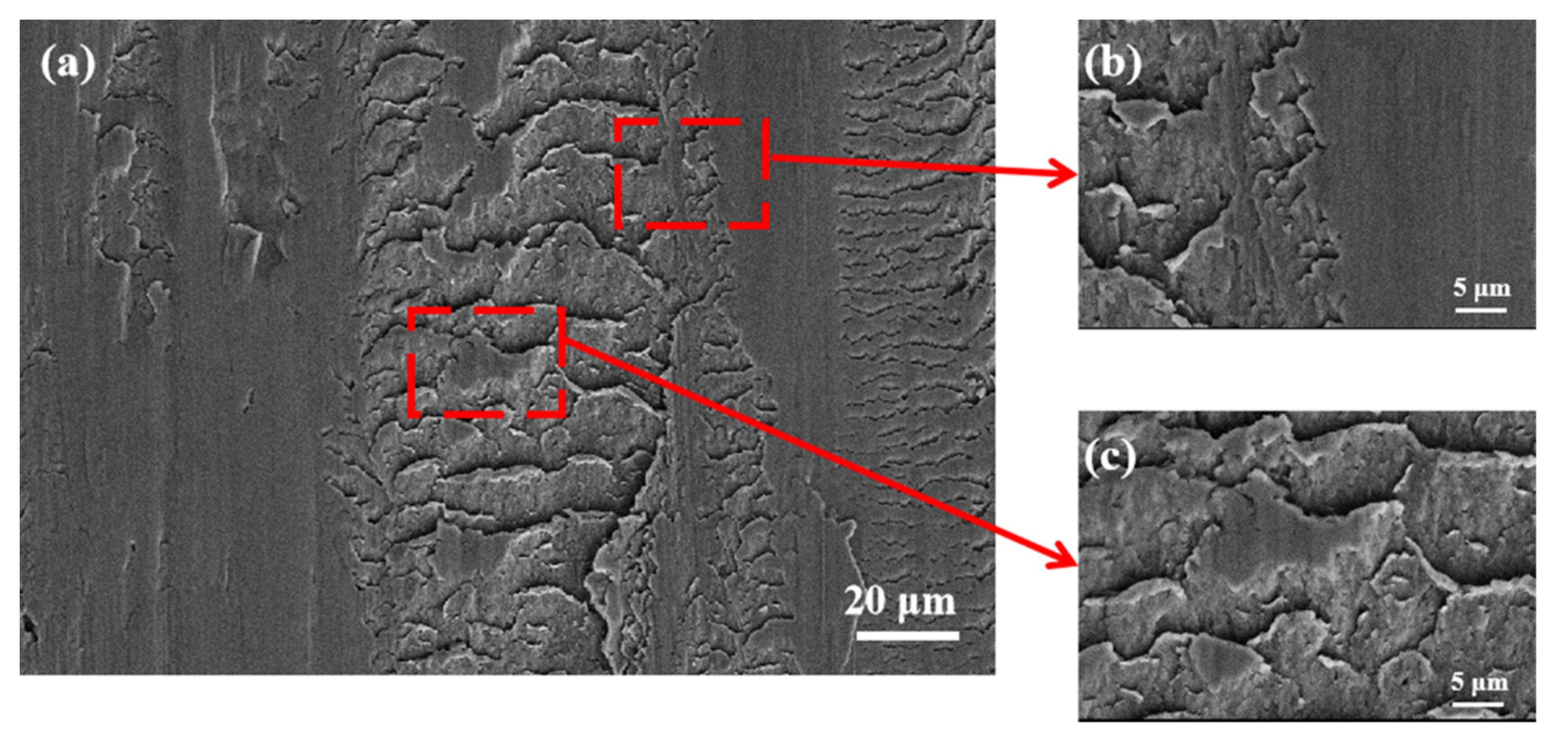
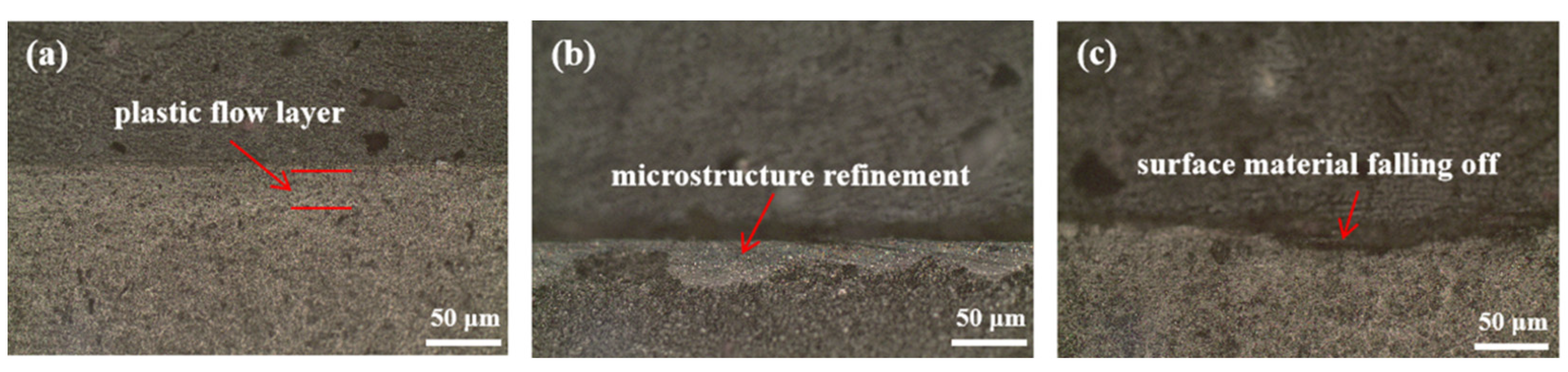
3.3. Wear Mechanism
4. Conclusions
- (1)
- With the extension of the bench test time, weight loss increased. The maximum weight loss occurs 1000 h after worn, which is about twice that of 350 h.
- (2)
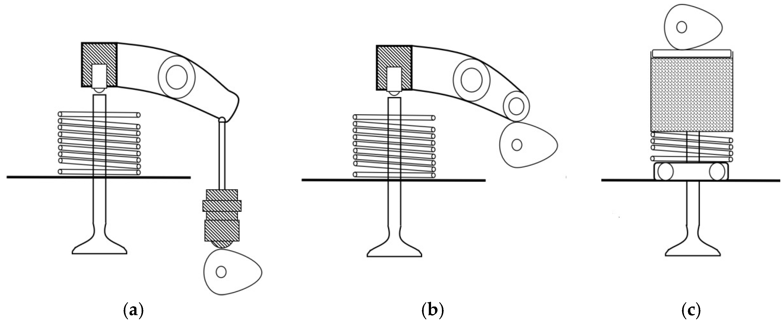
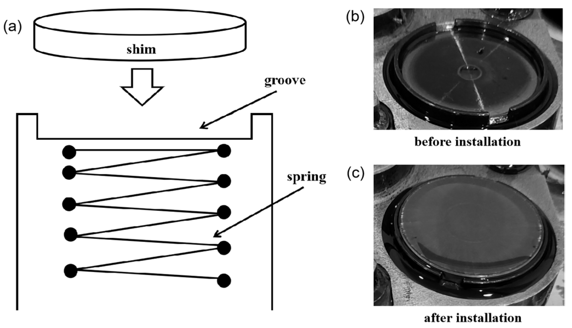
- When the cam base circle faced the shim, the two did not contact, and the shim was not stressed. When the cam rotated to the tip to contact the shim, the cam rolled the shim and compressed the spring due to pressure. The shim rotates slightly in the circumferential direction. Therefore, the wear marks on the shim surface appeared to diverge from the center to the edge of the shim.
- (3)
- During the wear process, a plastic flow of material was found on the subsurface, and fatigue wear marks occurred on the surface. With an increase in test time, the wear marks increased, leading to material spalling and the formation of pits. The wear mechanism was the mixed wear of fatigue wear and adhesive wear.
Author Contributions
Funding
Data Availability Statement
Conflicts of Interest
References
- Chen, J.T.; Yang, L.F. State-of-the-Art of Joining Technologies for Assembled Camshaft. Adv. Mater. Res. 2013, 602–604, 2118–2122. [Google Scholar] [CrossRef]
- Zhao, Y.X.; Zhang, K.S.; Di, J.J. Structural Design of Two-Cylinder Single Overhead Camshaft. In Proceedings of the 5th Annual International Conference on Material Science and Environmental Engineering, Xiamen, China, 15–17 December 2017; Volume 301, p. 012131. [Google Scholar]
- Lasota, I.; Protsenko, V.; Matyushkin, A.; Kuznetsov, M.; Gook, S. Laser surface hardening of engine camshaft cams. Mater. Today Proc. 2020, 30, 478–482. [Google Scholar] [CrossRef]
- Umar, M.; Mufti, R.A.; Khurram, M. Effect of flash temperature on engine valve train friction. Tribol. Int. 2018, 118, 170–179. [Google Scholar] [CrossRef]
- Ramírez, A.C.; García, E.C.; Alcalá, J.F.C.; Ramírez, J.T.; Hernández, A.M. Evaluation of CADI Low Alloyed with Chromium for Camshafts Application. Metals 2022, 12, 249. [Google Scholar] [CrossRef]
- Wang, G.; Zou, W.; Wu, B.; Wu, P.; Wu, H.; Chen, P.; Cui, B.; He, G.; Cai, R.; Qu, S. Analysis and countermeasures of early delamination of the nitrided tappet insterts in the valve train of a high speed and heavy load diesel engine. Eng. Fail. Anal. 2022, 138, 106338. [Google Scholar] [CrossRef]
- Lyu, B.; Meng, X.; Zhang, R.; Cui, Y. A Comprehensive Numerical Study on Friction Reduction and Wear Resistance by Surface Coating on Cam/Tappet Pairs under Different Conditions. Coatings 2020, 10, 485. [Google Scholar] [CrossRef]
- Marian, M.; Weikert, T.; Tremmel, S. On Friction Reduction by Surface Modifications in the TEHL Cam/Tappet-Contact-Experimental and Numerical Studies. Coatings 2019, 9, 843. [Google Scholar] [CrossRef]
- Ozkan, D.; Turkuz, C. Chromium nitride-coated copper beryllium as a cam tappet material candidate. Proc. Inst. Mech. Eng. Part C-J. Mech. Eng. Sci. 2020, 234, 3030–3046. [Google Scholar] [CrossRef]
- Ozkan, D.; Yilmaz, M.A.; Bakdemir, S.A.; Sulukan, E. Wear and Friction Behavior of TiB2 Thin Film-Coated AISI 52100 Steels under the Lubricated Condition. Tribol. Trans. 2020, 63, 1008–1019. [Google Scholar] [CrossRef]
- Özkan, D.; Erarslan, Y.; Sulukan, E.; Kara, L.; Yılmaz, M.A.; Yağcı, M.B. Tribological Behavior of TiAlN, AlTiN, and AlCrN Coatings at Boundary Lubricating Condition. Tribol. Lett. 2018, 66, 152. [Google Scholar] [CrossRef]
- Al-Jeboori, Y.; Kosarieh, S.; Ofune, M.; Morina, A.; Neville, A. Measuring Tappet Rotation in a Valvetrain Rig When Lubricated in a Fully Formulated Oil Containing MoDTC-type friction modifier. Tribol. Int. 2018, 121, 442–449. [Google Scholar] [CrossRef]
- Zahid, R.; Bhutta, M.U.; Mufti, R.A.; Abdullah, M.U.; Masjuki, H.H.; Varman, M.; Kalam, M.A.; Ali, M.A.; Aslam, J.; Akhtar, K. Friction and Wear Performance Evaluation of Bio-Lubricants and DLC Coatings on Cam/Tappet Interface of Internal Combustion Engines. Materials 2021, 14, 7206. [Google Scholar] [CrossRef] [PubMed]
- Zahid, R.; Hassan, M.H.; Alabdulkarem, A.; Varman, M.; Kalam, A.; Mufti, R.A.; Zulkifli, N.W.M.; Gulzar, M.; Bhutta, M.U.; Ali, M.A.; et al. Tribological characteristics comparison of formulated palm trimethylolpropane ester and polyalphaolefin for cam/tappet interface of direct acting valve train system. Ind. Lubr. Tribol. 2018, 70, 888–901. [Google Scholar] [CrossRef]
- Tang, H.W.; Wang, J.; Sun, N.N.; Zhu, J. Effect of angular speed of cam on oil film variation in the line contact thermal EHL of a cam-tappet pair. Ind. Lubr. Tribol. 2020, 72, 713–722. [Google Scholar] [CrossRef]
- Singh, P.; Goel, V. Effect of bio-lubricant on wear characteristics of cylinder liner-piston ring and cam-tappet combination in simulated environment. Fuel 2018, 233, 677–684. [Google Scholar] [CrossRef]
- Poonia, S.; Singh, A.; Singh, J.; Kumar, N.; Sharma, S. Parametric Study and Prediction of Lubrication Oil Film Thickness in Sliding and Rolling Interface Valve Trains; SAE Technical Paper; SAE International: Warrendale, PA, USA, 2018. [Google Scholar] [CrossRef]
- Meng, X.; Yu, C.; Xie, Y.; Mei, B. Thermal insulation effect on EHL of coated cam/tappet contact during start up. Ind. Lubr. Tribol. 2018, 70, 917–926. [Google Scholar] [CrossRef]
- Marian, M.; Tremmel, S.; Wartzack, S. Microtextured surfaces in higher loaded rolling-sliding EHL line-contacts. Tribol. Int. 2018, 127, 420–432. [Google Scholar] [CrossRef]
- Tremmel, S.; Marian, M.; Zahner, M.; Wartzack, S.; Merklein, M. Friction reduction in EHL contacts by surface microtexturing-tribological performance, manufacturing and tailored design. Ind. Lubr. Tribol. 2019, 71, 986–990. [Google Scholar] [CrossRef]
- Siczek, K.; Stefański, A. Analysis of dynamics and friction resistance in the cam-tappet system. J. Theor. Appl. Mech. 2019, 57, 273–286. [Google Scholar] [CrossRef]
- Orgeldinger, C.; Tremmel, S. Understanding Friction in Cam–Tappet Contacts—An Application-Oriented Time-Dependent Simulation Approach Considering Surface Asperities and Edge Effects. Lubricants 2021, 9, 106. [Google Scholar] [CrossRef]
- Hu, B.; Zhou, C.; Chen, S. Elastic dynamics modelling and analysis for a valve train including oil film stiffness and dry contact stiffness. Mech. Mach. Theory 2018, 131, 33–47. [Google Scholar] [CrossRef]
- Hu, B.; Li, Y.; Yin, L. Theoretical and Experimental Analysis of Dynamic Characteristics for a Valve Train System. Sensors 2021, 21, 6328. [Google Scholar] [CrossRef] [PubMed]
- Godiño, J.A.V.; García, M.T.; Aguilar, F.J.J.-E.; Guerrero, D.P. Failure analysis of an overhead valve train system in urban buses. Eng. Fail. Anal. 2018, 96, 455–467. [Google Scholar] [CrossRef]
- Jeng, Y.-R.; Tan, C.-M. Study of Nanoindentation Using FEM Atomic Model. J. Tribol. 2004, 126, 767–774. [Google Scholar] [CrossRef]
- Horstemeyer, M.F.; Baskes, M.I.; Godfrey, A.; Hughes, H.A. A large deformation atomistic study examining crystal orientation effects on the stress-strain relationship. Int. J. Plast. 2002, 18, 203–229. [Google Scholar] [CrossRef]


| Element | C | Si | Mn | Cr | Mo | P | S | Ni | Cu |
|---|---|---|---|---|---|---|---|---|---|
| Content/% | 0.95 | 0.15 | 0.25 | 1.40 | ≤0.10 | ≤0.025 | ≤0.025 | ≤0.30 | ≤0.25 |
Publisher’s Note: MDPI stays neutral with regard to jurisdictional claims in published maps and institutional affiliations. |
© 2022 by the authors. Licensee MDPI, Basel, Switzerland. This article is an open access article distributed under the terms and conditions of the Creative Commons Attribution (CC BY) license (https://creativecommons.org/licenses/by/4.0/).
Share and Cite
Li, C.-D.; Wang, J.-S.; Han, X.; Du, F.-M.; Liu, G.-S.; Lin, R.-J. Wear Performance of Circular Shim against Cam in Engine Bench Test. Materials 2022, 15, 6293. https://doi.org/10.3390/ma15186293
Li C-D, Wang J-S, Han X, Du F-M, Liu G-S, Lin R-J. Wear Performance of Circular Shim against Cam in Engine Bench Test. Materials. 2022; 15(18):6293. https://doi.org/10.3390/ma15186293
Chicago/Turabian StyleLi, Cheng-Di, Jing-Si Wang, Xu Han, Feng-Ming Du, Geng-Shuo Liu, and Ren-Jin Lin. 2022. "Wear Performance of Circular Shim against Cam in Engine Bench Test" Materials 15, no. 18: 6293. https://doi.org/10.3390/ma15186293
APA StyleLi, C.-D., Wang, J.-S., Han, X., Du, F.-M., Liu, G.-S., & Lin, R.-J. (2022). Wear Performance of Circular Shim against Cam in Engine Bench Test. Materials, 15(18), 6293. https://doi.org/10.3390/ma15186293