Quasi-In-Situ Analysis of As-Rolled Microstructure of Magnesium Alloys during Annealing and Subsequent Plastic Deformation

Abstract
:1. Introduction
2. Materials and Methods
2.1. Quasi-In Situ Heating EBSD Test
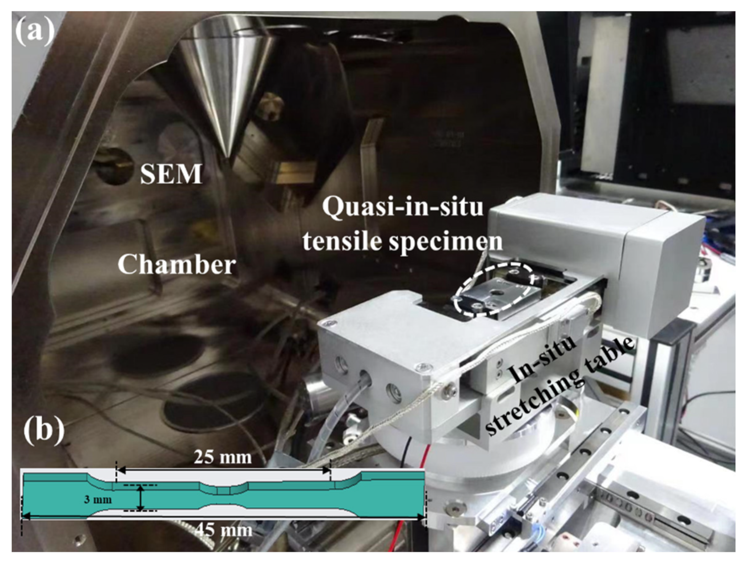
2.2. Quasi-In Situ Tensile EBSD Test
- (1)
- : basal<a>;
- (2)
- : prismatic<a>;
- (3)
- : first-order pyramidal<a>;
- (4)
- : second-order pyramidal<c+a>.
3. Results and Analysis
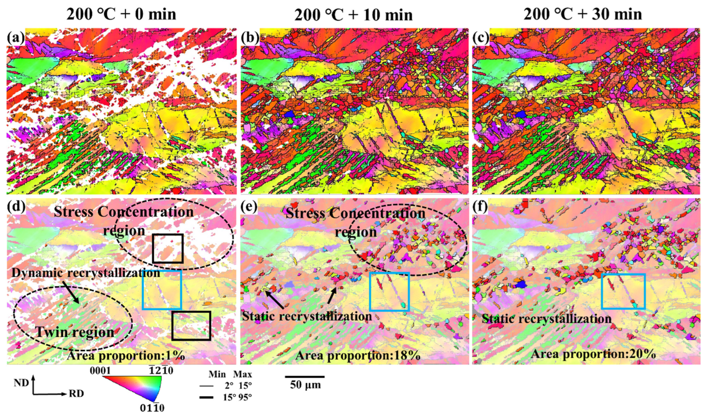
3.1. Recrystallization Behavior of the As-Rolled Microstructure
3.2. Plastic Deformation Behavior of Rolled Microstructure
3.2.1. Complete Recrystallization and Incomplete Recrystallization
3.2.2. The Grain Basal Orientation and Non-Basal Orientation
3.2.3. Large Grain Region and Small Grain Region
3.2.4. Small and Large Strain Regions
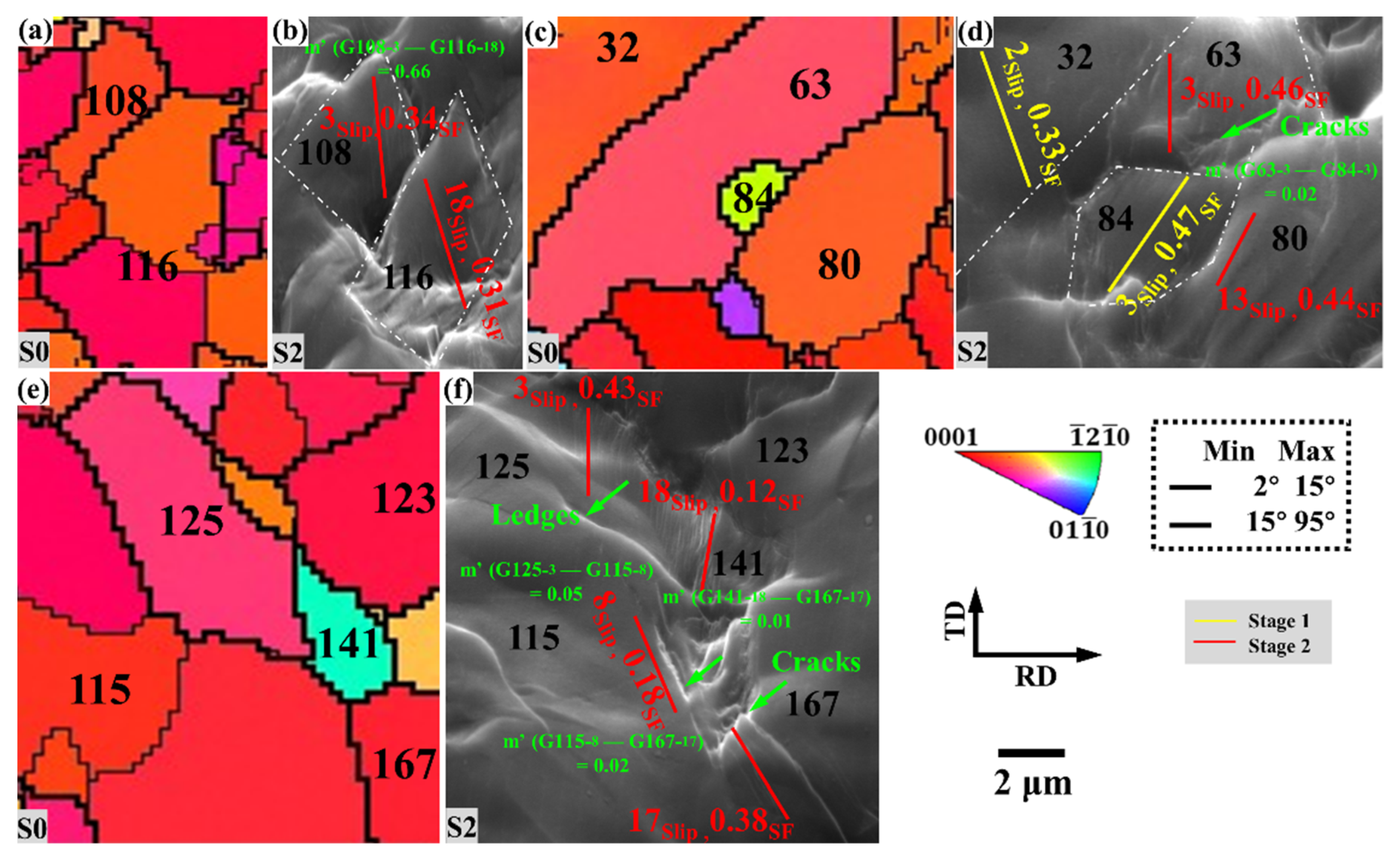
3.2.5. Crack-Forming Region
4. Conclusions
- Annealing recrystallization leads to grain reorganization, resulting in the diversity of grain orientation. Recrystallization preferentially nucleates in regions with high stress, and the generation of fine and equiaxed recrystallization contributes to grain refinement. However, it is difficult for recrystallization to occur in the region with less stress, which leads to the uneven distribution of the as-rolled structure of AZ31 magnesium alloys.
- The microstructure transformation and cracking of as-rolled AZ31 magnesium alloy during isothermal annealing and tensile deformation have the following characteristics:
- (1)
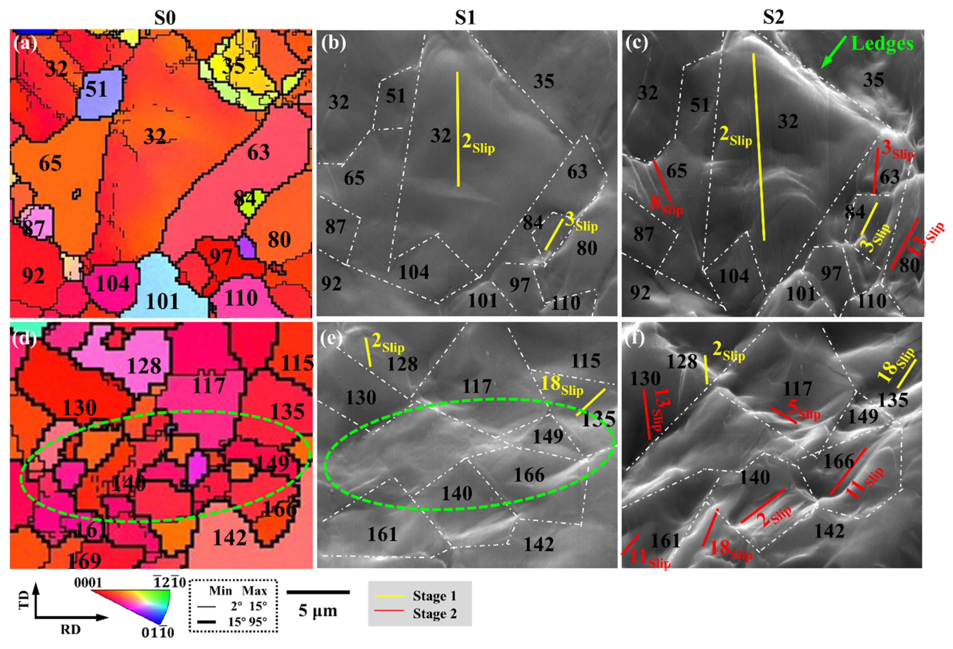
- Incomplete recrystallization is easier to accumulate dislocations than complete recrystallization, and ledges are formed in the early stage of deformation
- (2)
- The grain with non-basal orientation is easier to activate basal slip than basal-oriented grains.
- (3)
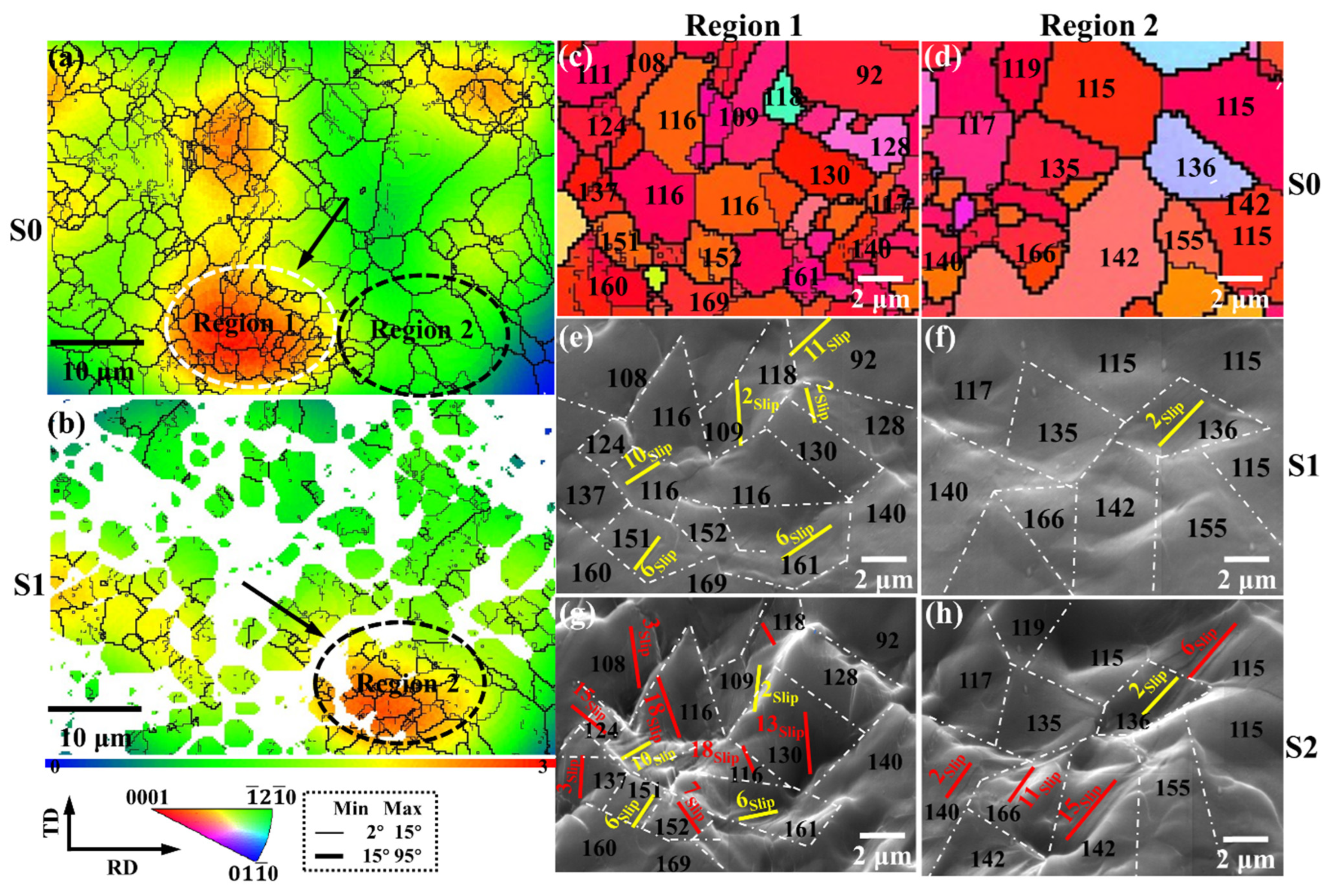
- Slip can be better transmitted between small grains, while deformation between large and small grains is difficult to transmit, which can easily lead to the generation of ledges.
- (4)
- The initial large-strain region is concentrated near the small-sized grains, and slip is preferentially activated in the early deformation stage, and the large-strain region transforms in the later stage of deformation.
- (5)
- Microcracks are more likely to occur between strain-incompatible grains.
Author Contributions
Funding
Institutional Review Board Statement
Informed Consent Statement
Data Availability Statement
Conflicts of Interest
References
- Yang, Y.; Xiong, X.; Chen, J.; Peng, X.; Chen, D.; Pan, F. Research advances in magnesium and magnesium alloys worldwide in 2020. J. Magnes. Alloy. 2021, 9, 705–747. [Google Scholar] [CrossRef]
- Song, J.; She, J.; Chen, D.; Pan, F. Latest research advances on magnesium and magnesium alloys worldwide. J. Magnes. Alloy. 2020, 8, 1–41. [Google Scholar] [CrossRef]
- Kim, J.N. Critical Assessment 6: Magnesium sheet alloys: Viable alternatives to steels? Mater. Sci. Technol. 2014, 30, 1925–1928. [Google Scholar] [CrossRef]
- You, S.; Huang, Y.; Kainer, K.U.; Hort, N. Recent research and developments on wrought magnesium alloys. J. Magnes. Alloy. 2017, 5, 239–253. [Google Scholar] [CrossRef]
- Li, S.; Yang, X.; Hou, J.; Du, W. A review on thermal conductivity of magnesium and its alloys. J. Magnes. Alloy. 2020, 8, 78–90. [Google Scholar] [CrossRef]
- Prasad, S.V.S.; Verma, K.; Mishra, R.K.; Kumar, V.; Singh, S. The role and significance of Magnesium in modern day research-A review. J. Magnes. Alloy. 2022, 10, 1–61. [Google Scholar] [CrossRef]
- Tian, J.; Deng, J.; Ma, R.; Chang, Y.; Liang, W.; Ma, J. Pre-control of annealing temperature on the uniformity of deformed structure of wrought magnesium alloy. Mater. Lett. 2021, 305, 130820. [Google Scholar] [CrossRef]
- Polmear, J.I. Magnesium alloys and applications. Met. Sci. J. 1994, 10, 1–16. [Google Scholar] [CrossRef]
- Rams, J.; Torres, B.; Pulido-González, N.; García-Rodriguez, S. Magnesium Alloys: Fundamentals and Recent Advances. In Encyclopedia of Materials: Metals and Alloys; Caballero, F.G., Ed.; Elsevier: Oxford, UK, 2022; pp. 2–10. [Google Scholar]
- Mordike, B.L.; Ebert, T. Magnesium: Properties—Applications—Potential. Mater. Sci. Eng. A 2001, 302, 37–45. [Google Scholar] [CrossRef]
- Tian, J.; Shi, Q.-X.; Meng, L.-X.; Deng, J.-F.; Liang, W.; Ma, J.-Y. Initiation and Suppression of Crack Propagation during Magnesium Alloy Rolling. Materials 2021, 14, 5217. [Google Scholar] [CrossRef]
- Shen, J.; Zhang, L.; Sun, Y.; Hu, L.; Yu, S.; Fang, A.; Yu, H. An exceptional ductility of AZ31 magnesium alloy sheet achieved by consecutive multi-pass cooperative lowered-temperature rolling. Mater. Sci. Eng. A 2022, 831, 142343. [Google Scholar] [CrossRef]
- Tian, J.; Lu, H.; Zhang, W.; Nie, H.; Shi, Q.; Deng, J.; Liang, W.; Wang, L. An effective rolling process of magnesium alloys for suppressing edge cracks: Width-limited rolling. J. Magnes. Alloy. 2022, 10, 2193–2207. [Google Scholar] [CrossRef]
- Tian, J.; Deng, J.; Shi, Q.; Chang, Y.; Liang, W.; Zhang, W. Effect of Temperature Field and Stress Field of Different Crack Behavior on Twins and Dislocations under Mg Alloy Rolling. Materials 2021, 14, 5668. [Google Scholar] [CrossRef] [PubMed]
- Ren, X.; Huang, Y.; Zhang, X.; Li, H.; Zhao, Y. Influence of shear deformation during asymmetric rolling on the microstructure, texture, and mechanical properties of the AZ31B magnesium alloy sheet. Mater. Sci. Eng. A 2021, 800, 140306. [Google Scholar] [CrossRef]
- Agnew, S.R.; Duygulu, Ö. Plastic anisotropy and the role of non-basal slip in magnesium alloy AZ31B. Int. J. Plast. 2005, 21, 1161–1193. [Google Scholar] [CrossRef]
- Bian, M.; Huang, X.; Chino, Y. Substantial improvement in cold formability of concentrated Mg–Al–Zn–Ca alloy sheets by high temperature final rolling. Acta Mater. 2021, 220, 117328. [Google Scholar] [CrossRef]
- Deng, J.-F.; Tian, J.; Zhou, Y.; Chang, Y.; Liang, W.; Ma, J. Plastic deformation mechanism and hardening mechanism of rolled Rare-Earth magnesium alloy thin sheet. Mater. Des. 2022, 218, 110678. [Google Scholar] [CrossRef]
- Zhang, K.; Shao, Z.; Jiang, J. Effects of twin-twin interactions and deformation bands on the nucleation of recrystallization in AZ31 magnesium alloy. Mater. Des. 2020, 194, 108936. [Google Scholar] [CrossRef]
- Basu, I.; Al-Samman, T. Competitive twinning behavior in magnesium and its impact on recrystallization and texture formation. Mater. Sci. Eng. A 2017, 707, 232–244. [Google Scholar] [CrossRef]
- Lee, S.-E.; Kim, M.-S.; Chae, Y.-W.; Guim, H.; Singh, J.; Choi, S.-H. Effect of intermediate heat treatment during hot rolling on the texture and formability of annealed AZ31 Mg alloy sheets. J. Alloys Compd. 2022, 897, 163238. [Google Scholar] [CrossRef]
- Yao, X.; Zheng, Y.; Quadir, M.; Kong, C.; Liang, J.; Chen, Y.; Munroe, P.; Zhang, D. Grain growth and recrystallization behaviors of an ultrafine grained Al-0.6 wt%Mg-0.4 wt%Si-5vol.%SiC nanocomposite during heat treatment and extrusion. J. Alloys Compd. 2018, 745, 519–524. [Google Scholar] [CrossRef]
- Ning, H.; Wang, C.; Xu, L.; Liu, S.; Zhang, K.; Zhou, X.; Wang, H. Influences of pre-aging precipitates on static recrystallization behavior of Mg–6Al–1Zn alloy. J. Mater. Res. Technol. 2022, 20, 35–46. [Google Scholar] [CrossRef]
- Chen, H.; Tang, J.; Gong, W.; Gao, Y.; Tian, F.; Chen, L. Effects of annealing treatment on the microstructure and corrosion behavior of hot rolled AZ31 Mg alloy. J. Mater. Res. Technol. 2021, 15, 4800–4812. [Google Scholar] [CrossRef]
- Doherty, R.; Hughes, D.; Humphreys, F.; Jonas, J.; Jensen, D.; Kassner, M.; King, W.; McNelley, T.; McQueen, H.; Rollett, A. Current issues in recrystallization: A review. Mater. Sci. Eng. A 1997, 238, 219–274. [Google Scholar] [CrossRef]
- Guan, D.; Rainforth, W.M.; Gao, J.; Sharp, J.; Wynne, B.; Ma, L. Individual effect of recrystallisation nucleation sites on texture weakening in a magnesium alloy: Part 1- double twins. Acta Mater. 2017, 135, 14–24. [Google Scholar] [CrossRef]
- Guan, D.; Rainforth, W.M.; Gao, J.; Ma, L.; Wynne, B. Individual effect of recrystallisation nucleation sites on texture weakening in a magnesium alloy: Part 2- shear bands. Acta Mater. 2018, 145, 399–412. [Google Scholar] [CrossRef]
- Guan, D.; Rainforth, W.M.; Ma, L.; Wynne, B.; Gao, J. Twin recrystallization mechanisms and exceptional contribution to texture evolution during annealing in a magnesium alloy. Acta Mater. 2017, 126, 132–144. [Google Scholar] [CrossRef]
- Tian, J.; Deng, J.-F.; Chang, Y.; Shi, Q.-X.; Liang, W.; Ma, J. A study of unstable fracture of a magnesium alloy caused by uneven microstructure. Mater. Lett. 2022, 314, 131799. [Google Scholar] [CrossRef]
- Yin, D.; Boehlert, C.; Long, L.; Huang, G.; Zhou, H.; Zheng, J.; Wang, Q. Tension-compression asymmetry and the underlying slip/twinning activity in extruded Mg–Y sheets. Int. J. Plast. 2021, 136, 102878. [Google Scholar] [CrossRef]
- Zhu, G.; Wang, L.; Zhou, H.; Wang, J.; Shen, Y.; Tu, P.; Zhu, H.; Liu, W.; Jin, P.; Zeng, X. Improving ductility of a Mg alloy via non-basal <a> slip induced by Ca addition. Int. J. Plast. 2019, 120, 164–179. [Google Scholar] [CrossRef]
- Deng, J.-f.; Tian, J.; Chang, Y.; Zhou, Y.; Liang, W.; Ma, J. The role of {10–12} tensile twinning in plastic deformation and fracture prevention of magnesium alloys. Mater. Sci. Eng. A 2022, 853, 143678. [Google Scholar] [CrossRef]
- Liu, B.-Y.; Prasad, K.E.; Yang, N.; Liu, F.; Shan, Z.-W. In-situ quantitative TEM investigation on the dynamic evolution of individual twin boundary in magnesium under cyclic loading. Acta Mater. 2019, 179, 414–423. [Google Scholar] [CrossRef]
- Nan, X.-L.; Wang, H.-Y.; Zhang, L.; Li, J.-B.; Jiang, Q.-C. Calculation of Schmid factors in magnesium: Analysis of deformation behaviors. Scr. Mater. 2012, 67, 443–446. [Google Scholar] [CrossRef]
- LusterM, J.; Morris, A. Compatibility of deformation in two-phase Ti-Al alloys: Dependence on microstructure and orientation relationships. Metall. Mater. Trans. A 1995, 26, 1745–1756. [Google Scholar] [CrossRef]
- Haouala, S.; Alizadeh, R.; Bieler, T.; Segurado, J.; Llorca, J. Effect of slip transmission at grain boundaries in Al bicrystals. Int. J. Plast. 2020, 126, 102600. [Google Scholar] [CrossRef] [Green Version]


Publisher’s Note: MDPI stays neutral with regard to jurisdictional claims in published maps and institutional affiliations. |
© 2022 by the authors. Licensee MDPI, Basel, Switzerland. This article is an open access article distributed under the terms and conditions of the Creative Commons Attribution (CC BY) license (https://creativecommons.org/licenses/by/4.0/).
Share and Cite
Deng, J.; Tian, J.; Zhou, Y.; Chang, Y.; Liang, W.; Ma, J. Quasi-In-Situ Analysis of As-Rolled Microstructure of Magnesium Alloys during Annealing and Subsequent Plastic Deformation. Materials 2022, 15, 6581. https://doi.org/10.3390/ma15196581
Deng J, Tian J, Zhou Y, Chang Y, Liang W, Ma J. Quasi-In-Situ Analysis of As-Rolled Microstructure of Magnesium Alloys during Annealing and Subsequent Plastic Deformation. Materials. 2022; 15(19):6581. https://doi.org/10.3390/ma15196581
Chicago/Turabian StyleDeng, Jiafei, Jing Tian, Yancai Zhou, Yuanying Chang, Wei Liang, and Jinyao Ma. 2022. "Quasi-In-Situ Analysis of As-Rolled Microstructure of Magnesium Alloys during Annealing and Subsequent Plastic Deformation" Materials 15, no. 19: 6581. https://doi.org/10.3390/ma15196581