
Invar/WC Composite Compacts Obtained by Spark Plasma Sintering from Mechanically Alloyed Powders
 , , , ,
Abstract
:1. Introduction
2. Experimental
3. Results and Discussions
4. Conclusions
Author Contributions
Funding
Conflicts of Interest
References
- Guillaume, C.-E. Invar. Nature 1933, 131, 658. [Google Scholar] [CrossRef]
- Qiu, C.; Adkins, N.J.E.; Attallah, M.M. Selective laser melting of Invar 36: Microstructure and properties. Acta Mater 2016, 10, 382–395. [Google Scholar] [CrossRef]
- Al-Dabbagh, J.B.; Al-Faluji, I.K.; Bin Hashim, Y. Thermal Expansion in Ferromagnetic Fe-Ni INVAR Alloy. Int. J. Eng. Sci. 2012, 1, 48–51. [Google Scholar]
- Masayuki, S. Invar alloys. Curr Opin Solid State Mater Sci. 1996, 1, 340–348. [Google Scholar] [CrossRef]
- Inaba, M.; Teshima, K.; Higashinakagawa, E.; Ohtake, Y. Development of an Invar (Fe-36Ni) shadow mask for color cathode ray tubes. IEEE Trans. Electron. Devices 1988, 35, 1721–1729. [Google Scholar] [CrossRef]
- Sahoo, A.; Medicherla, V.R.R. Fe-Ni Invar alloys: A review. Mater. Today 2021, 43, 2242–2244. [Google Scholar] [CrossRef]
- Sui, Q.; He, J.; Zhang, X.; Sun, Z.; Zhang, Y.; Wu, Y.; Zhu, Z.; Zhang, Q.; Peng, H. Strengthening of the Fe-Ni Invar Alloy Through Chromium. Materials 2019, 12, 1297. [Google Scholar] [CrossRef]
- Yao, Y.; Zhao, Q.; Zhang, C.; He, J.; Wu, Y.; Meng, G.; Chen, C.; Sun, Z.; Peng, H. Effect of warm rolling on microstructures and properties of the high strength invar alloy. J. Mater. Res. Technol. 2022, 19, 3046–3058. [Google Scholar] [CrossRef]
- Prică, C.V.; Neamțu, B.V.; Popa, F.; Marinca, T.F.; Sechel, N.; Chicinaș, I. Invar-type nanocrystalline compacts obtained by spark plasma sintering from mechanically alloyed powders. J Mater Sci. 2018, 53, 3735–3743. [Google Scholar] [CrossRef]
- Prică, C.V.; Neamțu, B.V.; Marinca, T.F.; Popa, F.; Sechel, N.; Isnard, O.; Chicinaș, I. Synthesis of Invar 36 type alloys from elemental and prealloyed powders by mechanical alloying. Powder Met. 2019, 62, 155–161. [Google Scholar] [CrossRef]
- Zhang, J.; Tu, Y.; Xu, J.; Zhang, J.; Zhang, J. Effect of Solid Solution Treatment on Microstructure of Fe-Ni Based High Strength Low Thermal Expansion Alloy. J. Iron Steel Res. Int. 2008, 15, 75–78. [Google Scholar] [CrossRef]
- Wang, R.M.; Song, Y.G.; Han, Y.F. Effect of rare earth on the microstructures and properties of a low expansion superalloy. J. Alloys Compd. 2000, 311, 160–164. [Google Scholar] [CrossRef]
- Abdulmenova, E.V.; Kashirina, V.I.; Kulkov, S.N. Studies of Invar Alloys Sintered from Powders Mixtures. AIP Conf. Proc. 2019, 2167, 020002. [Google Scholar] [CrossRef]
- Rodriguez, R.R.; Valenzuela, J.L.; Tabares, J.A.; Pérez Alcázar, G.A. Mössbauer and X-ray study of the Fe 65 Ni 35 invar alloy obtained by mechanical alloying. Hyperfine Interact 2014, 224, 323–330. [Google Scholar] [CrossRef]
- Dong, M.G.; Tishkevich, D.I.; Hanfid, M.Y.; Semenishchev, V.S.; Sayyed, M.I.; Zhou, S.Y.; Grabchikov, S.S.; Khanda, M.U.; Xue, X.X.; Zhaludkevich, A.L.; et al. W-Cu composites fabrication and experimental study of the shielding efficiency against ionizing radiation. Radiat. Phys. Chem. 2022, 110175. [Google Scholar] [CrossRef]
- Guillon, O.; Gonzalez-Julian, J.; Dargatz, B.; Kessel, T.; Schierning, G.; Rathel, J.; Herrmann, M. Field-Assisted Sintering Technology/Spark Plasma Sintering: Mechanisms, Materials, and Technology Developments. Adv. Eng. Mater. 2014, 16, 830–849. [Google Scholar] [CrossRef]
- Zhang, Z.H.; Liu, Z.F.; Lu, J.F.; Shen, X.B.; Wang, F.C.; Wang, Y.D. The sintering mechanism in spark plasma sintering—Proof of the occurrence of spark discharge. Scr. Mater. 2014, 81, 56–59. [Google Scholar] [CrossRef]
- Zheng, S.; Sokoluk, M.; Yao, G.; de Rosa, I.; Li, X. Fe–Ni Invar alloy reinforced by WC nanoparticles with high strength and low thermal expansion. SN Appl. Sci. 2019, 1, 172. [Google Scholar] [CrossRef]
- Vinogradov, A.; Hashimoto, S.; Kopylov, V.I. Enhanced strength and fatigue life of ultra-fine grain Fe/36Ni invar alloy. Mater. Sci Eng. A. 2003, 355, 277–285. [Google Scholar] [CrossRef]
- Li, X.C.; Stampfl, J.; Prinz, F.B. Mechanical and thermal expansion behavior of laser deposited metal matrix composites of Invar and TiC. Mat. Sci. Eng. A. 2000, 282, 86–90. [Google Scholar] [CrossRef]
- Sui, Q.S.; Li, J.X.; Zhai, Y.Z.; Sun, Z.H.; Wu, Y.F.; Zhao, H.T.; Feng, J.H.; Sun, M.C.; Yang, C.L.; Chen, B.A.; et al. Effect of alloying with V and Ti on microstructures and properties in Fe–Ni–Mo–C invar alloys. Materialia 2019, 8, 100474. [Google Scholar] [CrossRef]
- Nakama, K.; Tatsutani, S.; Sugita, K.; Shirai, Y. Strengthening of Fe-36mass% Ni low thermal expansion alloy by additions of C, V, Ti, and Cr and the effect of reducing Ni on thermal expansion. J. Jpn. Inst. Met. Mater. 2014, 78, 37–44. [Google Scholar] [CrossRef]
- Nakama, K.; Sugita, K.; Shirai, Y. Effect of MC Type Carbides on Age Hardness and Thermal Expansion of Fe–36 wt%Ni–0.2 wt%C. Metallogr. Microstruct. Anal. 2013, 2, 383–387. [Google Scholar] [CrossRef]
- Liu, H.; Sun, Z.; Wang, G.; Sun, X.; Li, J.; Xue, F.; Peng, H.; Zhang, Y. Effect of aging on microstructures and properties of Mo-alloyed Fe–36Ni invar alloy. Mat. Sci. Eng. A. 2016, 654, 107–112. [Google Scholar] [CrossRef]
- Sakaguchi, N.; Ohno, H.; Nakada, N. Strengthening of Super Invar Cast Steel by Precipitation of Intermetallic Compounds. ISIJ Int. 2022, 62, 1532–1539. [Google Scholar] [CrossRef]
- Onoue, M.; Trimarchi, G.; Freeman, A.J.; Popescu, V.; Matsen, M.R. Magnetization of ternary alloys based on Fe0.65Ni0.35 invar with 3d transition metal additions: An ab initio study. J. Appl. Phys. 2015, 117, 043912. [Google Scholar] [CrossRef]
- Ni, J.E.; Case, E.D.; Schmidt, R.D.; Wu, C.I.; Hogan, T.P.; Trejo, R.M.; Kirkham, M.J.; Lara-Curzio, E.; Kanatzidis, M.G. The thermal expansion coefficient as a key design parameter for thermoelectric materials and its relationship to processing dependent bloating. J. Mater. Sci. 2013, 48, 6233–6244. [Google Scholar] [CrossRef]
- Nie, Q.; Chen, G.; Wang, B.; Yang, L.; Zhang, J.; Tang, W. Effect of Invar particle size on microstructures and properties of the Cu/Invar bi-metal matrix composites fabricated by SPS. J. Alloys Compd. 2022, 891, 162055. [Google Scholar] [CrossRef]
- Khan, S.A.; Ziya, A.B.; Ibrahim, A.; Atiq, S.; Usman, M.; Ahmad, N.; Shakeel, M. Enhancement of Curie temperature (Tc) and magnetization of Fe–Ni Invar alloy through Cu substitution and with He+2 ion irradiation. J. Electron. Mater. 2016, 45, 2258–2265. [Google Scholar] [CrossRef]
- Sokolowski, W.M.; Jacobs, S.F.; Lane, M.S.; O’Donnell, T.P.; Hsieh, C. Dimensional stability of high-purity In Proceedings of the SPIE’S 1993 International Symposium on Optics, Imaging, and Instrumentation. San Diego, CA, USA, 11–16 July 1993. [Google Scholar] [CrossRef]
- Reeber, R.R.; Wang, K. Thermophysical Properties of α-Tungsten Carbide. J. Am. Ceram. Soc. 2004, 82, 129–135. [Google Scholar] [CrossRef]
- Chong, X.Y.; Jiang, Y.H.; Zhou, R.; Zhu, H.; Feng, J. Electronic structure, anisotropic elastic and thermal properties of the η phase Fe6W6C. Comput. Mater. Sci. 2015, 108, 205–211. [Google Scholar] [CrossRef]


| Composite Powder | D10 (µm) | D50 (µm) | D90 (µm) |
|---|---|---|---|
| Invar | 24.8 | 54.3 | 199.4 |
| Invar + 5% WC | 29.8 | 56.8 | 154.6 |
| Invar + 10% WC | 32.7 | 68.8 | 138.6 |
| Invar + 15% WC | 22.1 | 53.2 | 108.2 |
| Sample | Sintering Temperature (°C) | Density (g/cm3) | Relative Density (%) |
|---|---|---|---|
| Invar + 5% WC | 800 | 7.45 | 83.8 |
| Invar + 10% WC | 700 | 7.29 | 76.2 |
| Invar + 10% WC | 800 | 7.52 | 78.6 |
| Invar + 10% WC | 900 | 7.58 | 83.4 |
| Invar + 15% WC | 800 | 7.29 | 71.2 |
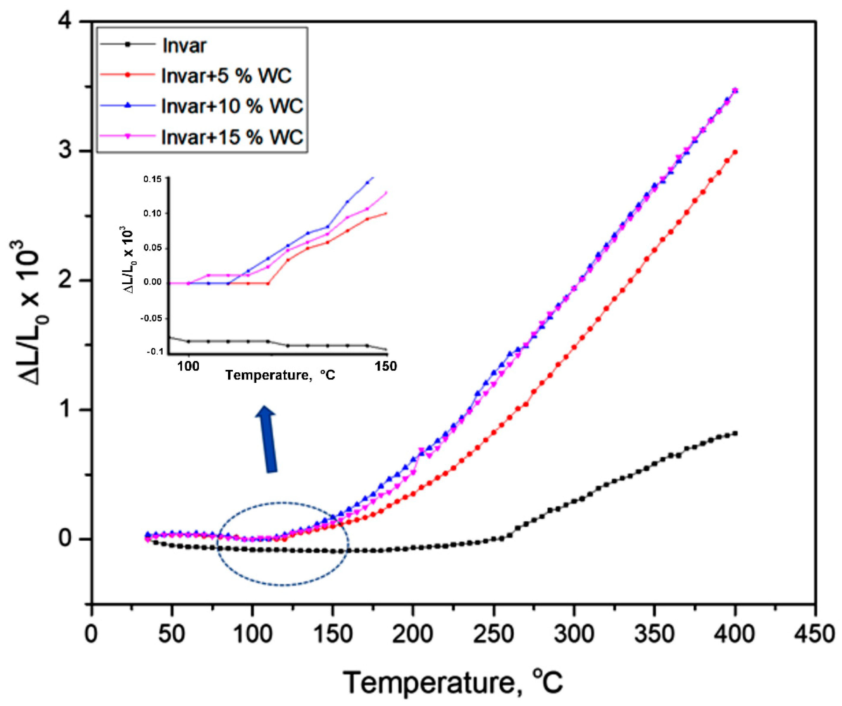
| Sample—Sintered at 800 °C | Temperature Range, ΔT (°C) | α × 106 (°C−1) |
|---|---|---|
| Invar | 20–250 250–400 | 0.6 10.0 |
| Invar + 5% WC | 20–120 120–400 | 1.0 10.6 |
| Invar + 10% WC | 20–105 105–400 | 1.0 11.9 |
| Invar + 15% WC | 20–100 100–400 | 1.0 12.3 |
| Sample | Sintering Temperature (°C) | Hardness (HB) | Relative Density (%) |
|---|---|---|---|
| Invar + 5% WC | 800 | 36 | 83.8 |
| Invar + 10% WC | 700 | 32 | 76.2 |
| Invar + 10% WC | 800 | 64 | 78.6 |
| Invar + 10% WC | 900 | 73 | 83.4 |
| Invar + 15% WC | 800 | 67 | 71.2 |
Publisher’s Note: MDPI stays neutral with regard to jurisdictional claims in published maps and institutional affiliations. |
© 2022 by the authors. Licensee MDPI, Basel, Switzerland. This article is an open access article distributed under the terms and conditions of the Creative Commons Attribution (CC BY) license (https://creativecommons.org/licenses/by/4.0/).
Share and Cite
Prica, C.-V.; Marinca, T.F.; Neamțu, B.V.; Sechel, A.N.; Popa, F.; Jozsa, E.M.; Chicinaș, I. Invar/WC Composite Compacts Obtained by Spark Plasma Sintering from Mechanically Alloyed Powders. Materials 2022, 15, 6714. https://doi.org/10.3390/ma15196714
Prica C-V, Marinca TF, Neamțu BV, Sechel AN, Popa F, Jozsa EM, Chicinaș I. Invar/WC Composite Compacts Obtained by Spark Plasma Sintering from Mechanically Alloyed Powders. Materials. 2022; 15(19):6714. https://doi.org/10.3390/ma15196714
Chicago/Turabian StylePrica, Călin-Virgiliu, Traian Florin Marinca, Bogdan Viorel Neamțu, Argentina Niculina Sechel, Florin Popa, Elekes Marton Jozsa, and Ionel Chicinaș. 2022. "Invar/WC Composite Compacts Obtained by Spark Plasma Sintering from Mechanically Alloyed Powders" Materials 15, no. 19: 6714. https://doi.org/10.3390/ma15196714