
High Temperature Degradation Mechanism of Concrete with Plastering Layer

Abstract
:1. Introduction
2. Materials and Methods
2.1. Test Procedure
2.2. Test Materials
2.3. Test Method
2.3.1. Concrete Slump Test
2.3.2. Heating Test
2.3.3. Ultrasonic Pulse Velocity Test
2.3.4. Concrete Compressive Strength Test
2.3.5. X-ray Diffraction (XRD) Analysis
2.3.6. SEM Observation
2.3.7. Thermogravimetric Analysis (TGA)
3. Results
3.1. Concrete Slump Test
3.2. Appearance of Concrete after Heating Test
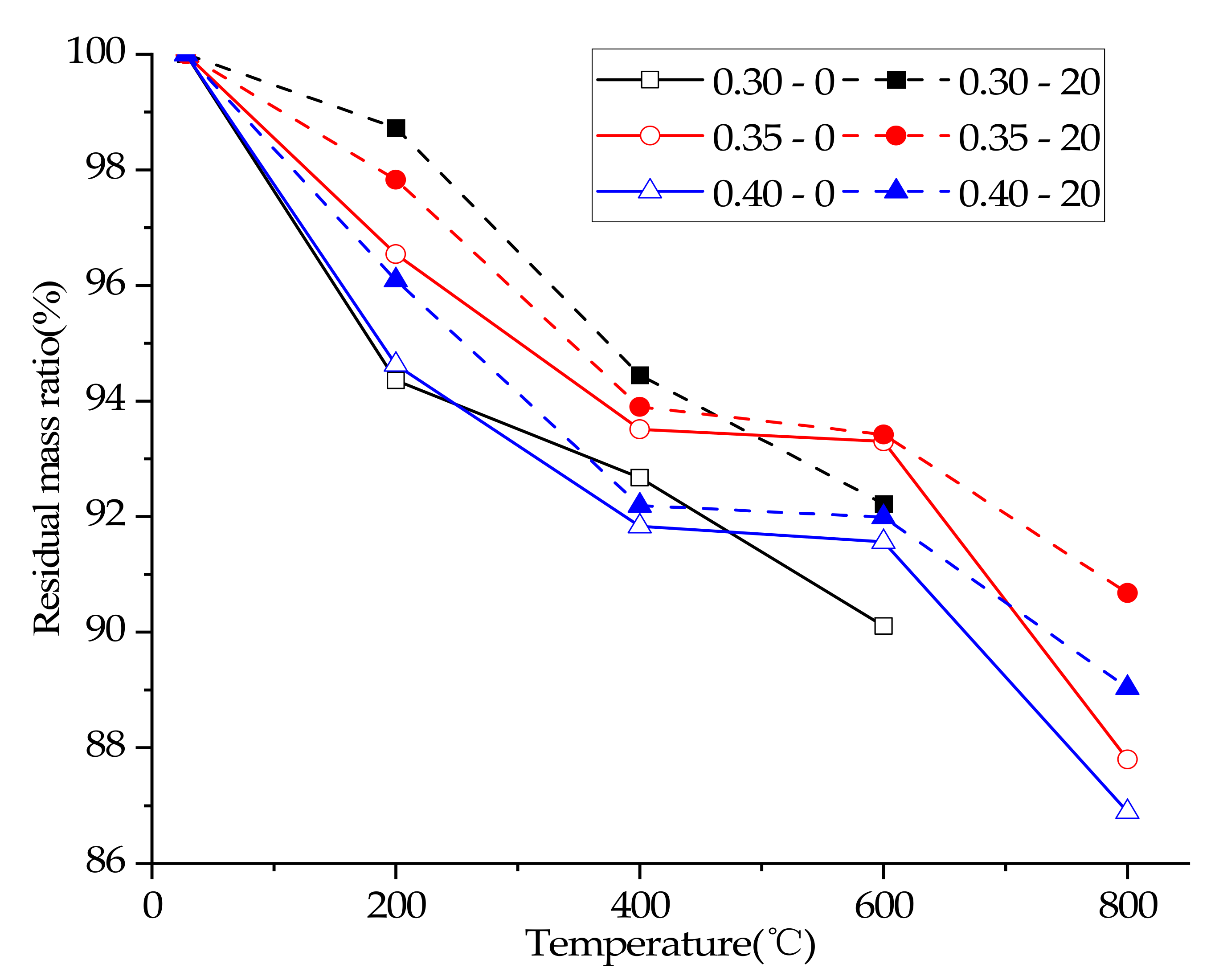
3.3. Residual Mass Ratio
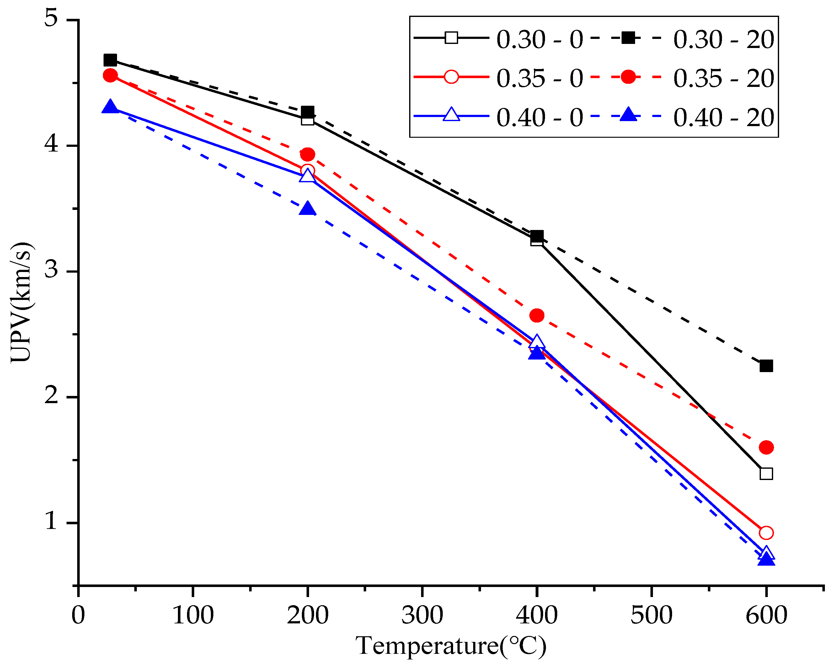
3.4. Ultrasonic Pulse Velocity
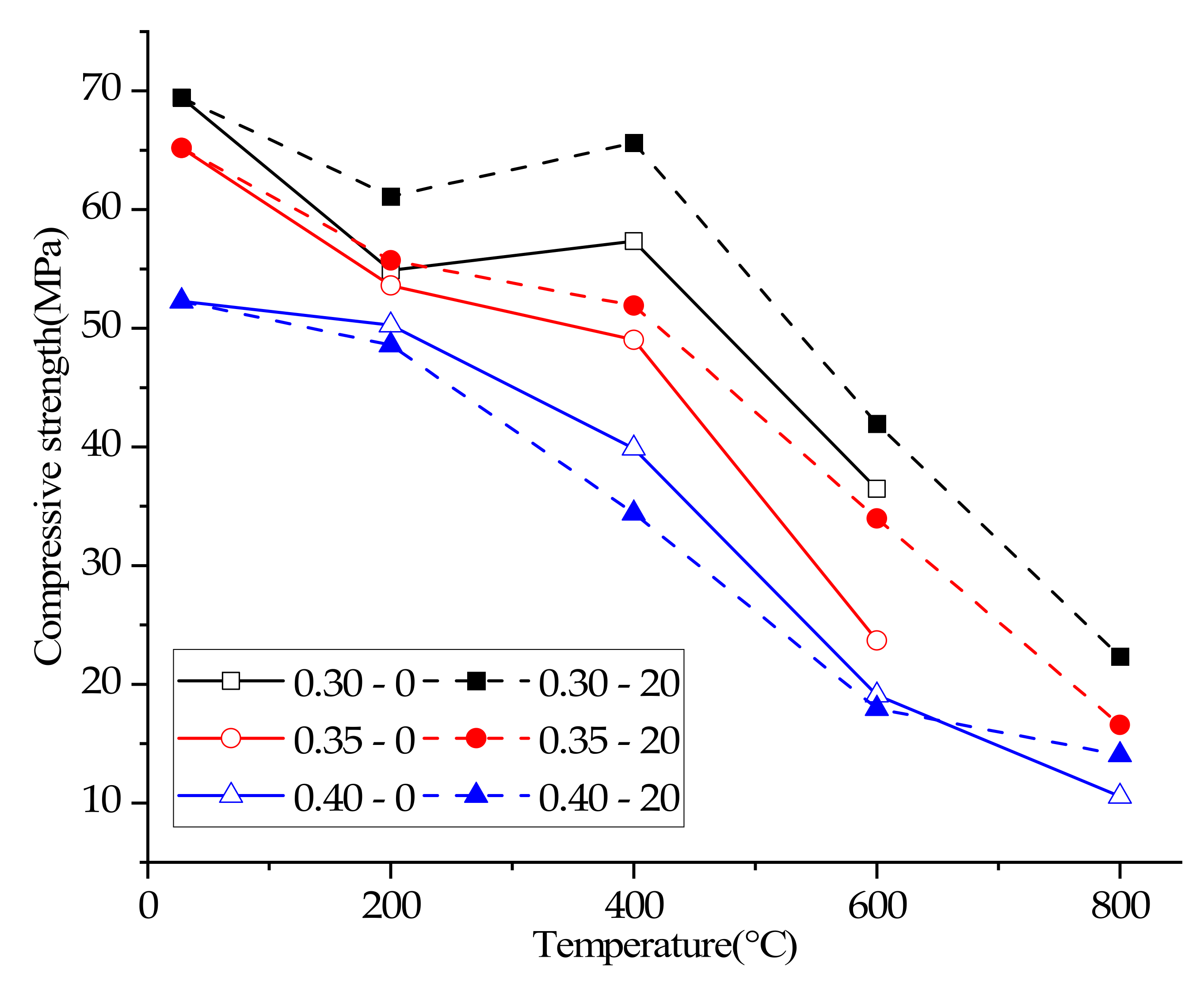
3.5. Compressive Strength
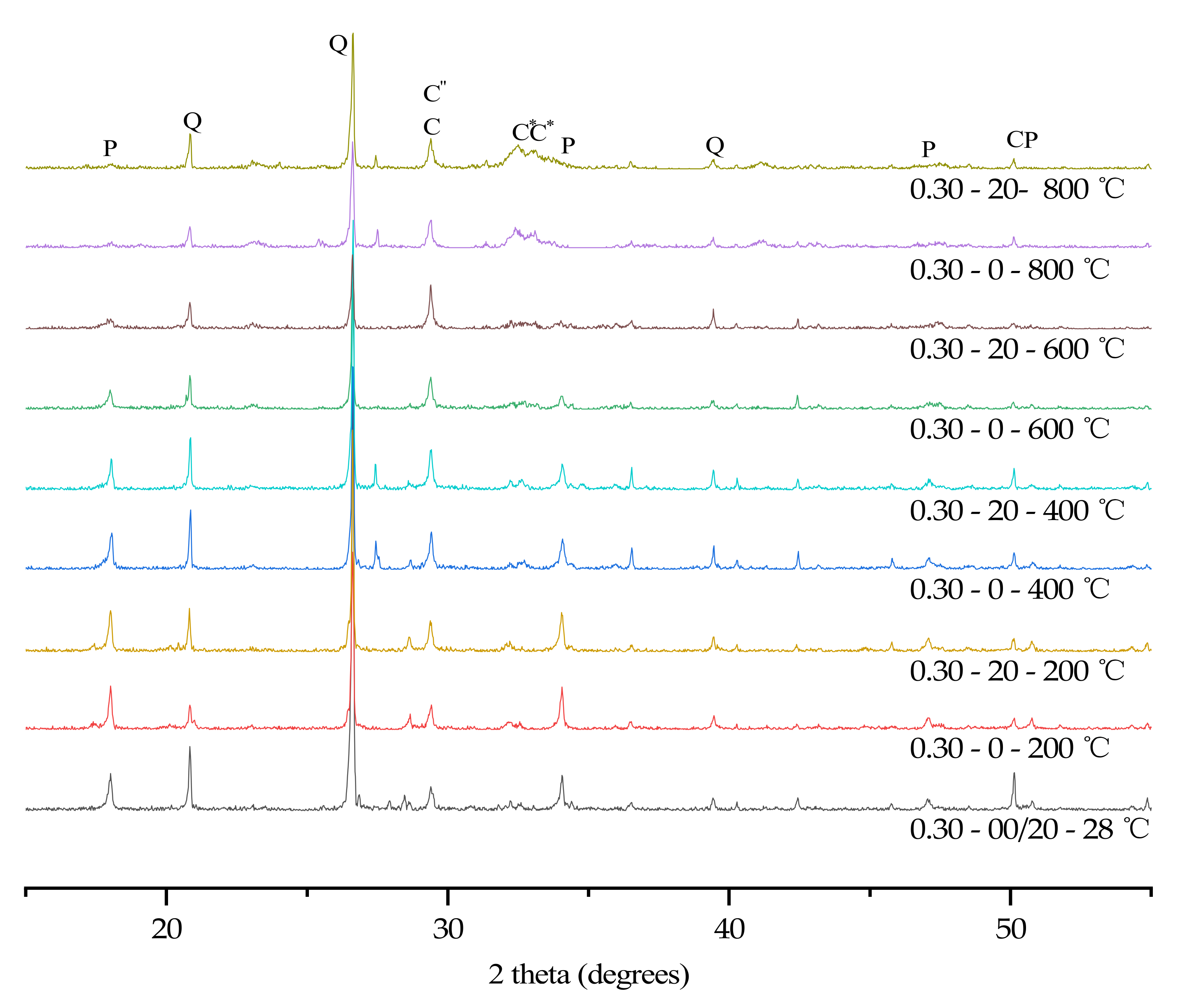
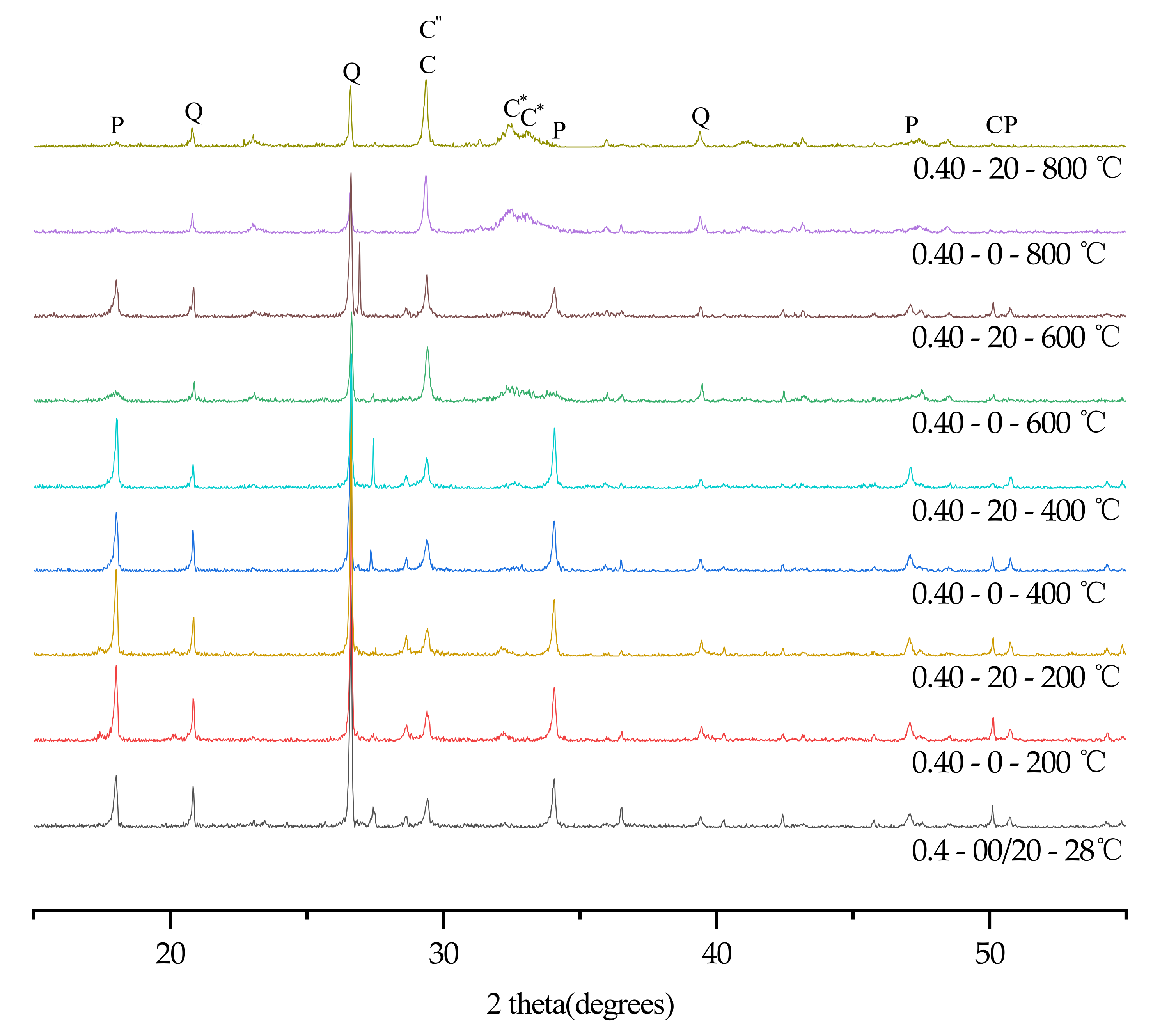
3.6. XRD
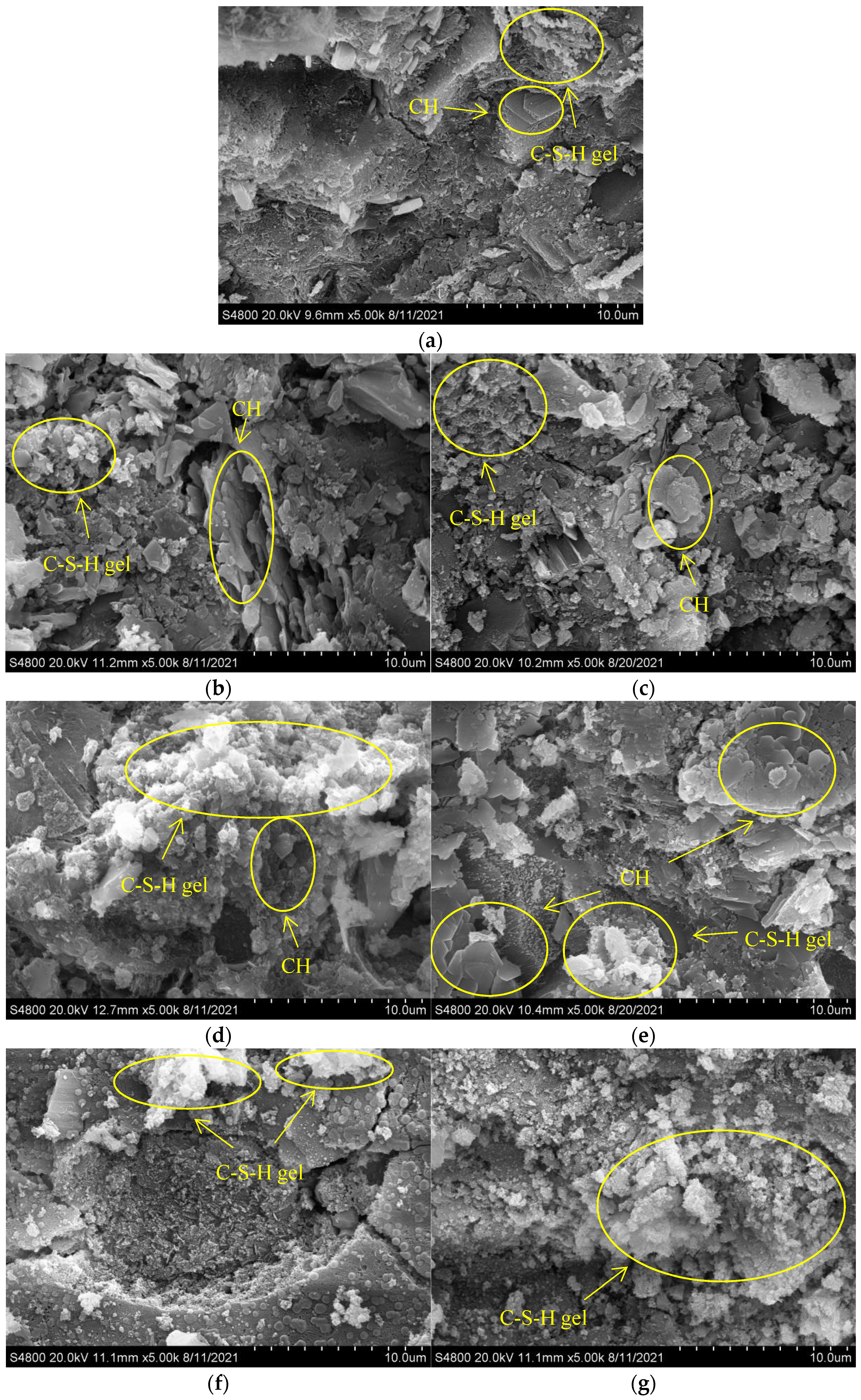
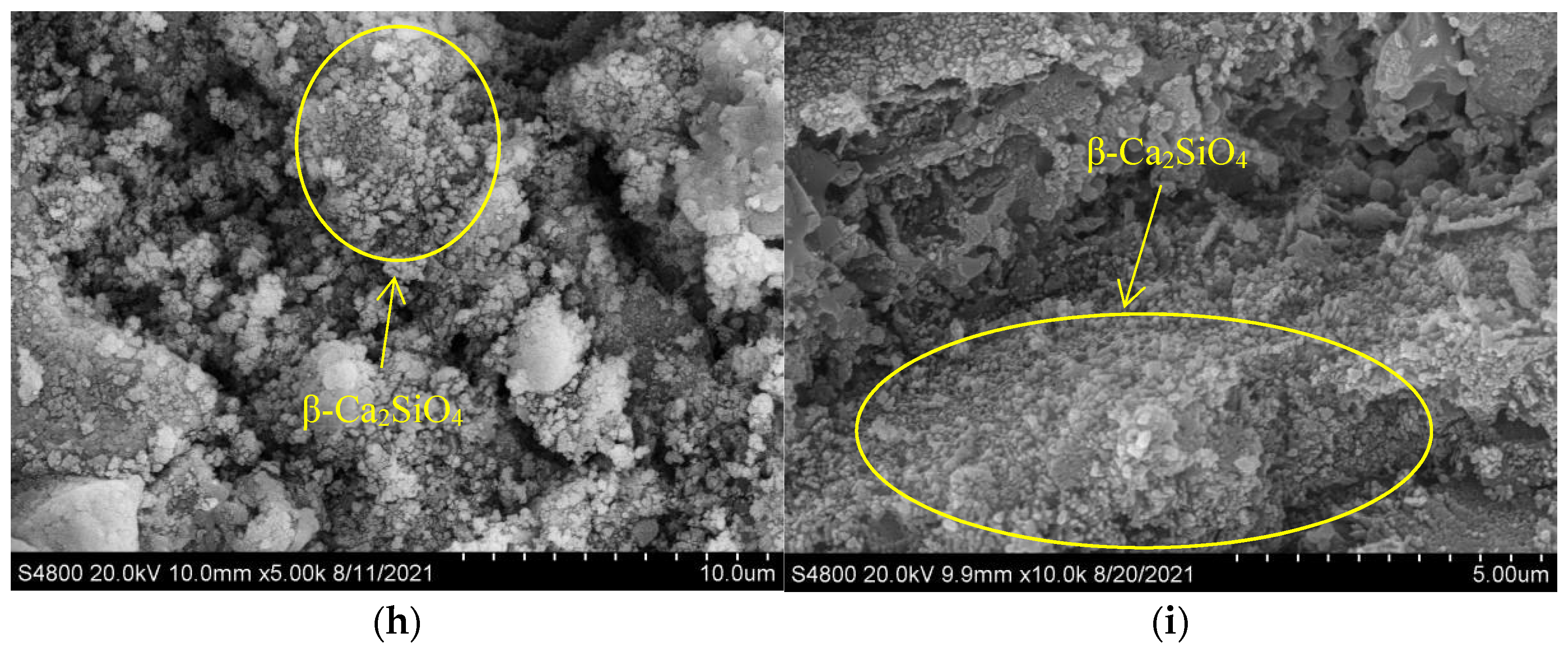
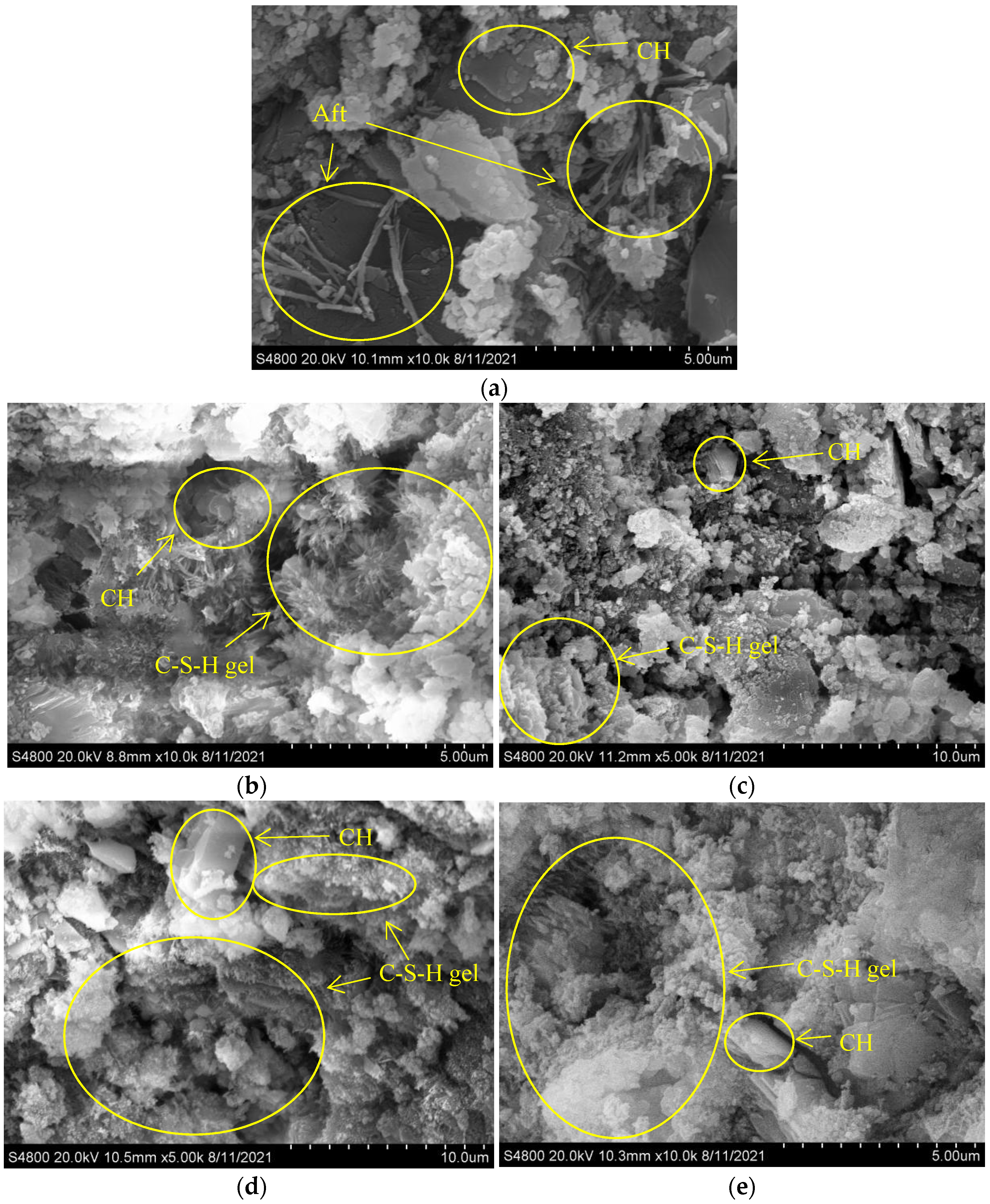
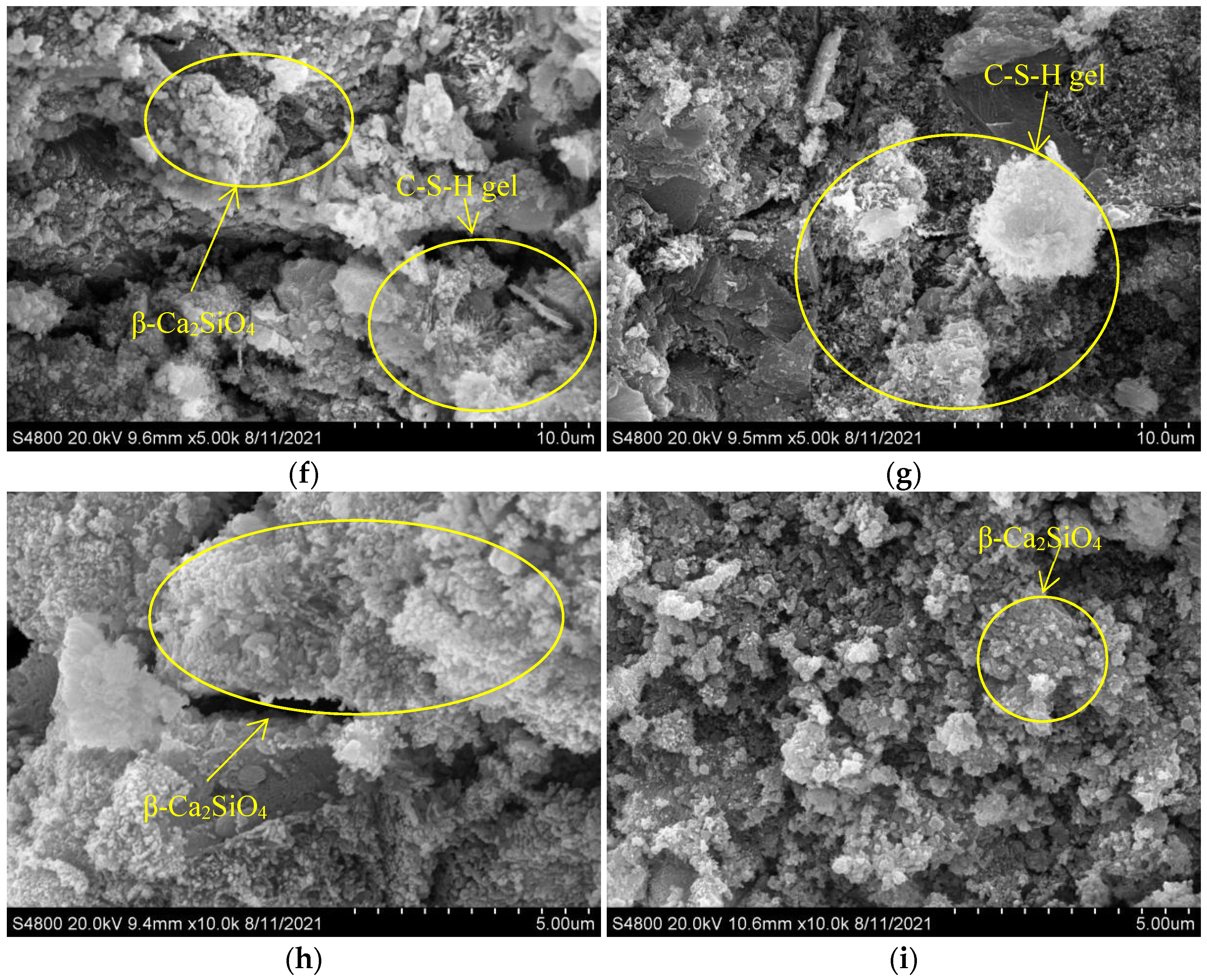
3.7. SEM
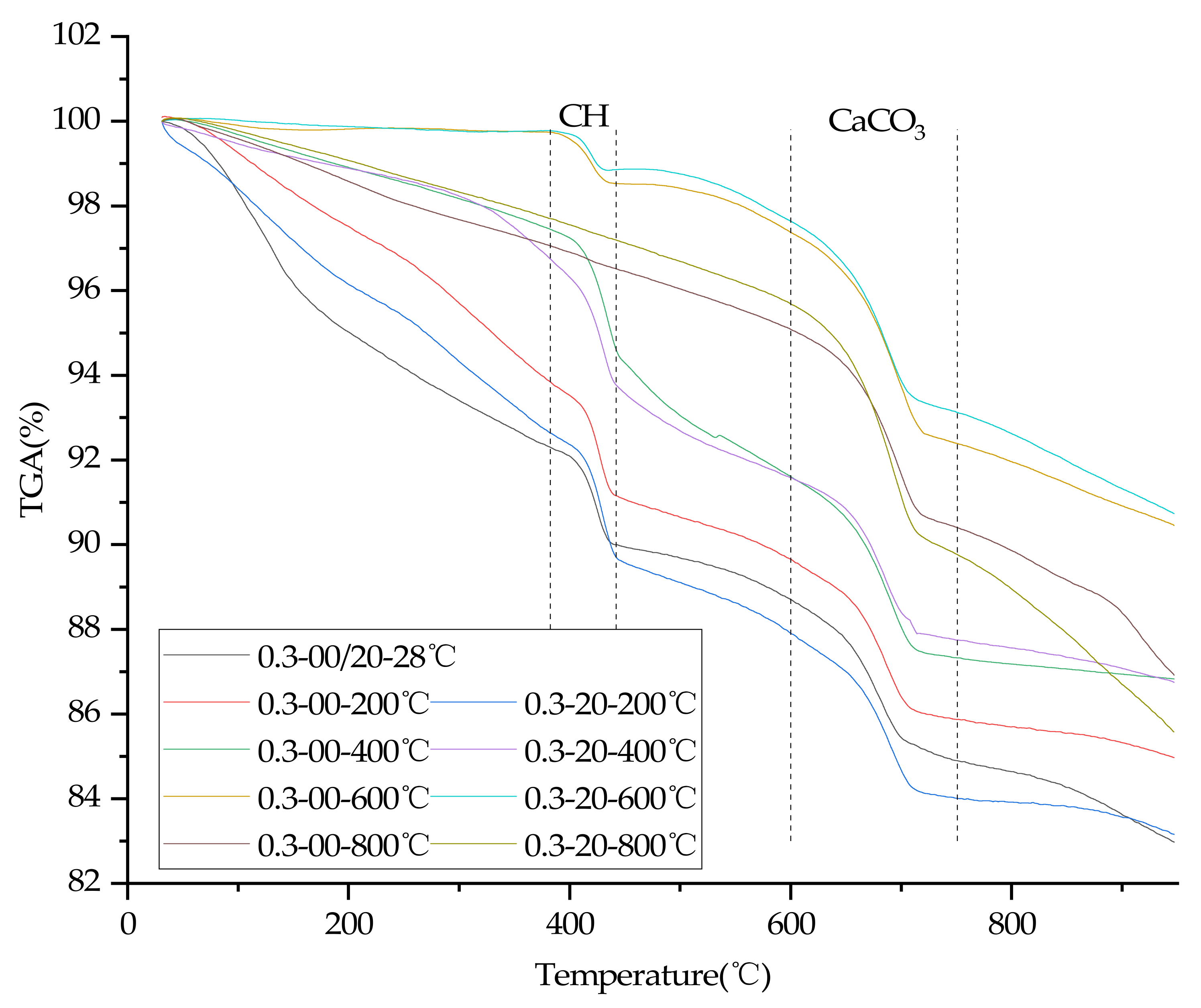
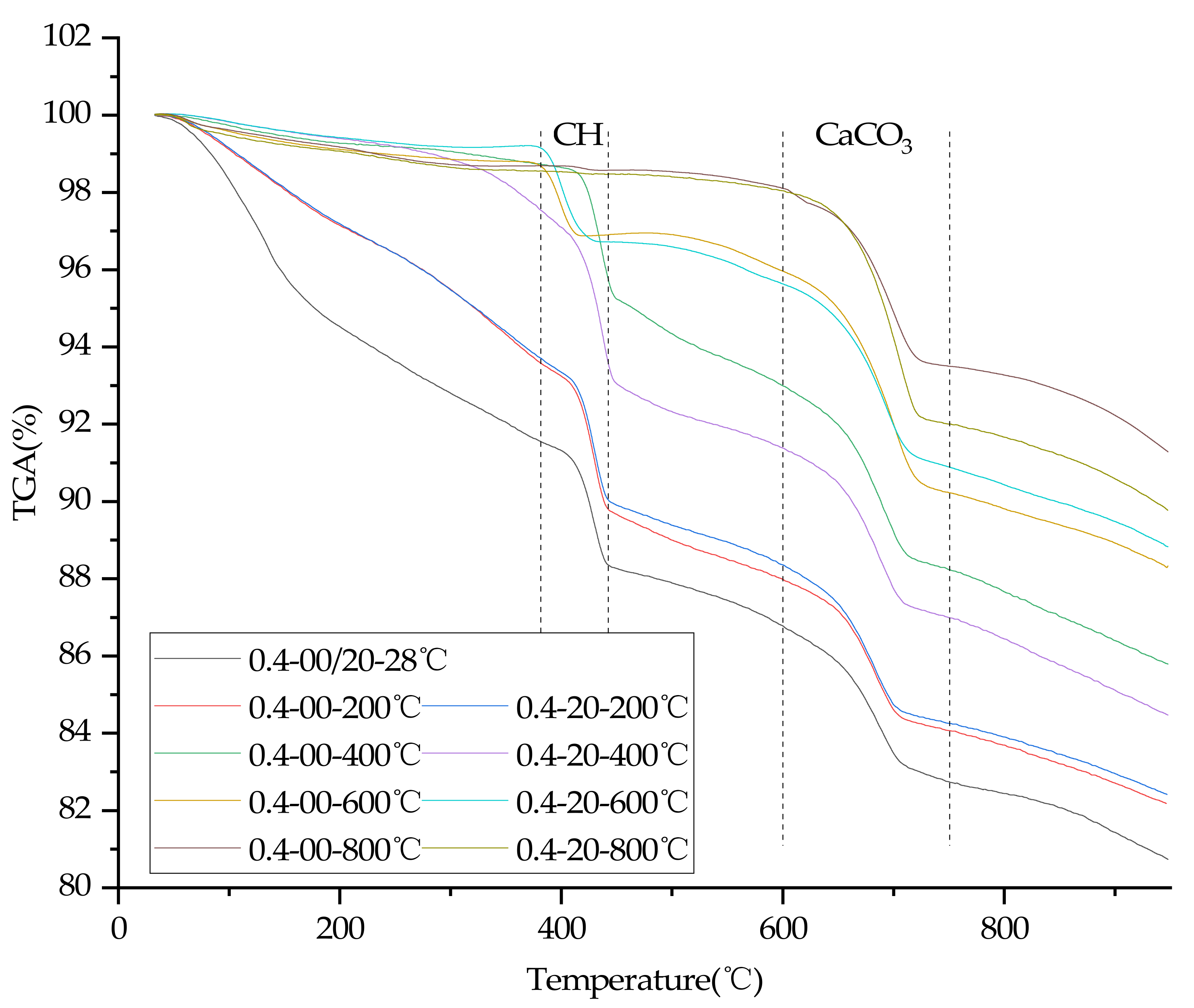
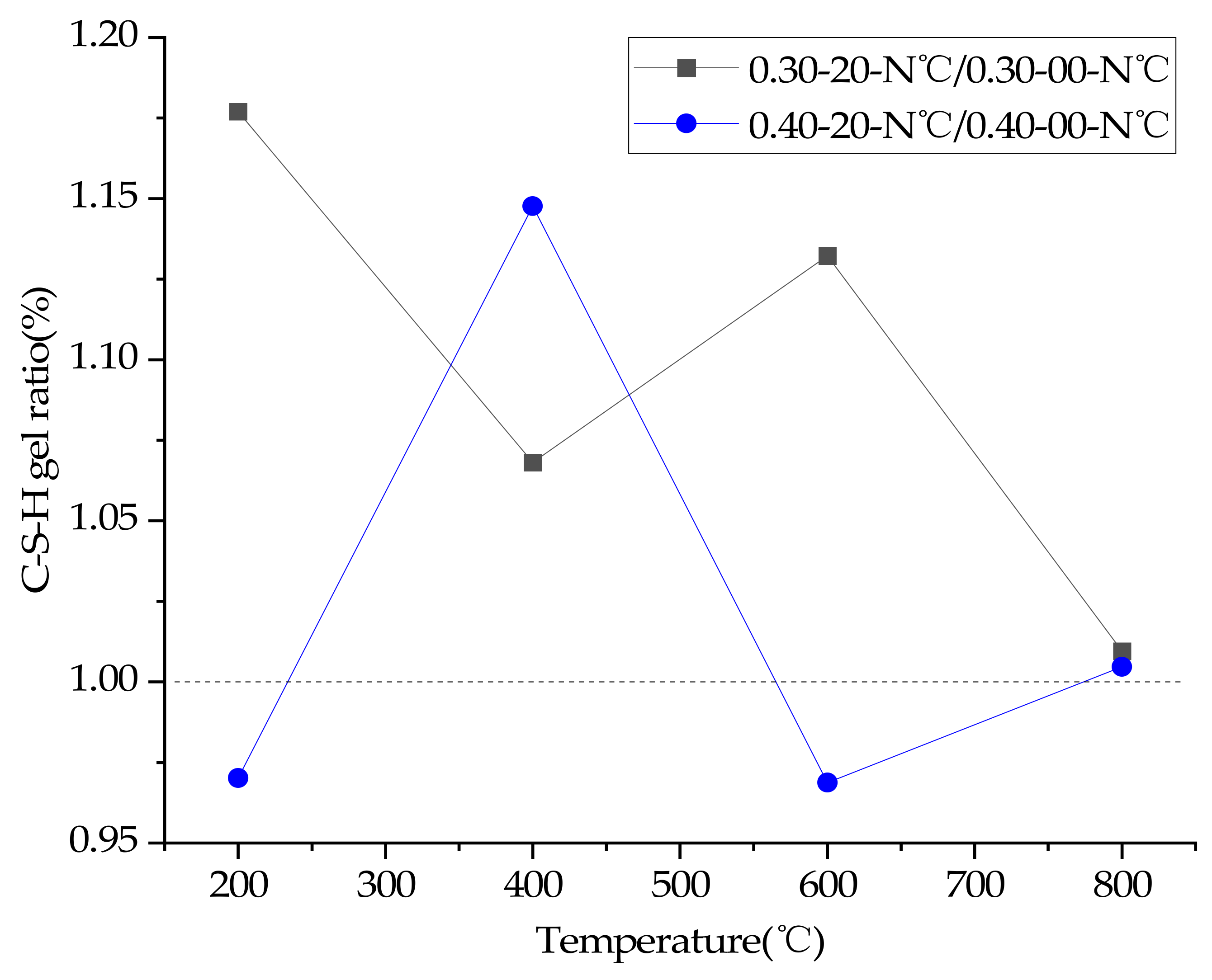
3.8. TGA
4. Discussion of Results
5. Conclusions
- (1)
- Reducing the water/cement ratio can improve the strength of concrete at any temperature, but too low water/cement ratio can easily cause high temperature cracking, and ultimately lead to the decline of high temperature resistance of concrete. Under the condition of no plastering layer, all concrete with a water/cement ratio of 0.3 or 0.35 cannot be tested for compressive strength by spalling and explosion at 800 °C. Concrete with a water/cement ratio of 0.4 can still be tested for compressive strength despite obvious cracking.
- (2)
- After exposure to a high temperature (400 °C), the compressive strength of 0.30–0–400 °C was 4.48% higher than 0.30–0–200 °C, and the compressive strength of 0.30–20–400 °C was 7.38% higher than 0.30–20–200 °C. The increase of compressive strength can be attributed to the hydration of unhydrated cement particles of concrete and the Van der Waals force.
- (3)
- A plastering layer can accelerate or decelerate the damage of concrete at high temperatures, which depends on the water/cement ratio of concrete. A plaster layer at a high temperature can inhibit water vapor’s escape to promote the hydration of unhydrated cement in concrete with a low water/cement ratio (0.3) to delay the loss of the compressive strength of concrete. However due to the high hydration rate of concrete with a high water/cement ratio (0.4) the plaster layer cannot delay the loss of the compressive strength of concrete at high temperatures and can even exacerbate the loss of the compressive strength of concrete. Therefore, the plastering layer can increase the compressive strength of concrete with a 0.3 water/cement ratio by 11.35–15.02% between 200 °C and 800 °C and increase the compressive strength of concrete with a 0.35 water/cement ratio by 3.95–43.33% between 200 °C and 800 °C. However, the plastering layer decreases the compressive strength of concrete with 0.4 water/cement ratio between 200–600 °C, and increases the compressive strength by 33.40% at 800 °C.
- (4)
- The compressive strength of concrete after heating is affected by the water/cement ratio and plastering layer, so the influence of the water cement/ratio and plastering layer should be considered when calculating the fire resistance limit and residual load capacity of concrete members under fire, and the reduction factor should not be directly used to calculate the strength of concrete (especially concrete with a low water/cement) after heating.
Author Contributions
Funding
Institutional Review Board Statement
Informed Consent Statement
Conflicts of Interest
References
- Fire Prevention and Response in China in 2020. Available online: www.119.gov.cn/article/41kpo4CAQyv (accessed on 1 February 2021).
- Yazici, S.; Sezer, G.I.; Senguel, H. The effect of high temperature on the compressive strength of mortars. Constr. Build. Mater. 2012, 35, 97–100. [Google Scholar] [CrossRef]
- Moghadam, M.A.; Izadifard, R.A. Effects of zeolite and silica fume substitution on the microstructure and mechanical properties of mortar at high temperatures. Constr. Build. Mater. 2020, 253, 119206. [Google Scholar] [CrossRef]
- Yang, J.; Peng, G.F.; Zhao, J.; Shui, G.S. On the explosive spalling behavior of ultra-high performance concrete with and without coarse aggregate exposed to high temperature. Constr. Build. Mater. 2019, 226, 932–944. [Google Scholar] [CrossRef]
- Kong, D.L.Y.; Sanjayan, J.G. Effect of elevated temperatures on geopolymer paste, mortar and concrete. Cem. Concr. Res. 2010, 40, 334–339. [Google Scholar] [CrossRef]
- Uygunoglu, T.; Topcu, I.B. Thermal expansion of self-consolidating normal and lightweight aggregate concrete at elevated temperature. Constr. Build. Mater. 2009, 23, 3063–3069. [Google Scholar] [CrossRef]
- Nalon, G.H.; Ribeiro, J.C.L.; Araújo, E.N.D.D.; Pedroti, L.G.; de Carvalho, J.M.F.; Santos, R.F.; de Oliveira, D.S. Residual mechanical properties of mortars containing carbon nanomaterials exposed to high temperatures. Constr. Build. Mater. 2021, 275, 122123. [Google Scholar] [CrossRef]
- Ingham, J.P. Application of petrographic examination techniques to the assessment of fire-damaged concrete and masonry structures. Mater. Charact. 2009, 60, 700–709. [Google Scholar] [CrossRef]
- Pawel, S.; Mohamed, A.E.; Dietmar, S. The influence of nanomaterials on the thermal resistance of cement-based composites-a review. Nanomaterials 2018, 8, 465. [Google Scholar]
- Ibrahim, R.K.; Hamid, R.; Taha, M.R. Fire resistance of high-volume fly ash mortars with nanosilica addition. Constr. Build. Mater. 2012, 36, 779–786. [Google Scholar] [CrossRef]
- Kalifa, P.; Chene, G.; Galle, C. High-temperature behaviour of HPC with polypropylene fibres from spalling to microstructure. Cem. Concr. Res. 2001, 31, 1487–1499. [Google Scholar] [CrossRef]
- Liu, J.C.; Tan, K.H.; Yao, Y. A new perspective on nature of fire-induced spalling in concrete. Constr. Build. Mater. 2018, 184, 581–590. [Google Scholar] [CrossRef]
- Liang, X.; Wu, C.; Su, Y.; Chen, Z.; Li, Z. Development of ultra-high performance concrete with high fire resistance. Constr. Build. Mater. 2018, 179, 400–412. [Google Scholar] [CrossRef]
- Kodur, V.K.R.; Khaliq, W. Effect of temperature on thermal properties of different types of high-strength concrete. J. Mater. Civ. Eng. 2021, 23, 793–801. [Google Scholar] [CrossRef]
- Lima, N.B.; Junior, V.R.; Belarmino, M.K.; Silva, A.I.; Ioras, R.U.; Oliveira, R.A.; Lima, N.B. A chemical rationalization of the processing and application of the mortar coatings: Structural, thermodynamic, and fluorescence properties. J. Mol. Struct. 2018, 1164, 546–555. [Google Scholar] [CrossRef]
- Selvaranjan, K.; Navaratnam, S.; Gamage, J.C.P.H.; Thamboo, J.; Siddique, R.; Zhang, J.; Zhang, G. Thermal and environmental impact analysis of rice husk ash-based mortar as insulating wall plaster. Constr. Build. Mater. 2021, 283, 122774. [Google Scholar] [CrossRef]
- Hodhod, O.A.; Rashad, A.M.; Abdel-Razek, M.M.; Ragab, A.M. Coating protection of loaded RC columns to resist elevated temperature 2009. Fire Saf. J. 2009, 44, 241–249. [Google Scholar] [CrossRef]
- Kovalov, A.; Otrosh, Y.; Ostroverkh, O. Fire resistance evaluation of reinforced concrete floors with fire-retardant coating by calculation and experimental method. E3S Web Conf. 2018, 60, 00003. [Google Scholar] [CrossRef] [Green Version]
- Allam, S.M.; Elbakry, H.; Rabeai, A.G. Behavior of one-way reinforced concrete slabs subjected to fire. AEJ-Alex. Eng. J. 2013, 52, 749–761. [Google Scholar] [CrossRef] [Green Version]
- Carlos, T.B.; Rodrigues, J.P.C.; de Lima, R.C.; Dhima, D. Experimental analysis on flexural behaviour of RC beams strengthened with CFRP laminates and under fire conditions. Compos. Struct. 2018, 189, 516–528. [Google Scholar] [CrossRef]
- Du, H.; Hu, X.; Xie, Z.; Meng, Y. Experimental and analytical investigation on fire resistance of glulam-concrete composite beams. J. Build. Eng. 2021, 44, 103244. [Google Scholar] [CrossRef]
- Balaji, A.; Nagarajan, P.; Pillai, T.M. Studies on the behavior of Reinforced Concrete Short Column subjected to fire. Alex. Eng. J. 2016, 55, 475–486. [Google Scholar] [CrossRef] [Green Version]
- Noumowe, A.N.; Siddique, R.; Debicki, G. Permeability of high-performance concrete subjected to elevated temperature (600 °C). Constr. Build. Mater. 2009, 23, 1855–1861. [Google Scholar] [CrossRef]
- Sukontasukkul, P.; Pomchiengpin, W.; Songpiriyakij, S. Post-crack (or post-peak) flexural response and toughness of fiber reinforced concrete after exposure to high temperature. Constr. Build. Mater. 2010, 24, 1967–1974. [Google Scholar] [CrossRef]
- Hou, X.M.; Zheng, W.Z.; Kodur, V.K.R. Response of unbonded prestressed concrete continuous slabs under fire exposure. Eng. Struct. 2013, 56, 2139–2148. [Google Scholar] [CrossRef]
- Bui, N.K.; Satomi, T.; Takahashi, H. Effect of mineral admixtures on properties of recycled aggregate concrete at high temperature. Constr. Build. Mater. 2018, 184, 361–373. [Google Scholar] [CrossRef]
- Lin, Y.; Hsiao, C.; Yang, H.; Lin, Y.F. The effect of post-fire-curing on strength-velocity relationship for nondestructive assessment of fire-damaged concrete strength. Fire Saf. J. 2011, 46, 178–185. [Google Scholar] [CrossRef]
- Uysal, M.; Yilmaz, K.; Ipek, M. Properties and behavior of self-compacting concrete produced with GBFS and FA additives subjected to high temperatures. Constr. Build. Mater. 2012, 28, 321–326. [Google Scholar] [CrossRef]
- Omer, S.A.; Demirboga, R.; Khushefati, W.H. Relationship between compressive strength and UPV of GGBFS based geopolymer mortars exposed to elevated temperatures. Constr. Build. Mater. 2015, 94, 189–195. [Google Scholar] [CrossRef]
- Mehdizadeh, H.; Jia, X.; Mo, K.H.; Ling, T.C. Effect of water-to-cement ratio induced hydration on the accelerated carbonation of cement pastes. Environ. Pollut. 2021, 280, 116914. [Google Scholar] [CrossRef]
- Dai, J.; Wang, Q.; Lou, X.; Bao, X.; Zhang, B.; Wang, J.; Zhang, X. Solution calorimetry to assess effects of water/cement ratio and low temperature on hydration heat of cement-sciencedirect. Constr. Build. Mater. 2020, 269, 121222. [Google Scholar] [CrossRef]
- Aydın, S.; Baradan, B. Effect of pumice and fly ash incorporation on high temperature resistance of cement based mortars. Cem. Concr. Res. 2007, 37, 988–995. [Google Scholar] [CrossRef]
- Hager, I. Behaviour of cement concrete at high temperature. Bull. Pol. Acad. Sci. Tech. Sci. 2013, 61, 145–154. [Google Scholar] [CrossRef]
- Lim, S. Effects of Elevated Temperature Exposure on Cement-Based Composite Materials. Ph.D. Thesis, University of Illinois at Urbana-Champaign, Urbana, IL, USA, 2015. [Google Scholar]
- Ghasan, F.H.; Joudah, Z.H.; Sam, A.R.M. Compressive strength and microstructure properties of modifified concrete incorporated effective microorganism and flfly ash. Mater. Today Proc. 2021, 46, 2036–2044. [Google Scholar]

| Mix No. | W/C Ratio | Cement (kg/m3) | Water (kg/m3) | Fine Aggregate (kg/m3) | Coarse Aggregate (kg/m3) | Water Reducer (g/m3) |
|---|---|---|---|---|---|---|
| 0.30–0–25 °C | 0.30 | 633.8 | 190.1 | 720.9 | 917.4 | 3300 |
| 0.30–0–200 °C | ||||||
| 0.30–0–400 °C | ||||||
| 0.30–0–600 °C | ||||||
| 0.30–0–800 °C | ||||||
| 0.30–20–25 °C | ||||||
| 0.30–20–200 °C | ||||||
| 0.30–20–400 °C | ||||||
| 0.30–20–600 °C | ||||||
| 0.30–20–800 °C | ||||||
| 0.35–0–25 °C | 0.35 | 587.3 | 205.5 | 720.9 | 917.4 | 2000 |
| 0.35–0–200 °C | ||||||
| 0.35–0–400 °C | ||||||
| 0.35–0–600 °C | ||||||
| 0.35–0–800 °C | ||||||
| 0.35–20–25 °C | ||||||
| 0.35–20–200 °C | ||||||
| 0.35–20–400 °C | ||||||
| 0.35–20–600 °C | ||||||
| 0.35–20–800 °C | ||||||
| 0.40–0–25 °C | 0.40 | 547.1 | 218.8 | 720.9 | 917.4 | 400 |
| 0.40–0–200 °C | ||||||
| 0.40–0–400 °C | ||||||
| 0.40–0–600 °C | ||||||
| 0.40–0–800 °C | ||||||
| 0.40–20–25 °C | ||||||
| 0.40–20–200 °C | ||||||
| 0.40–20–400 °C | ||||||
| 0.40–20–600 °C | ||||||
| 0.40–20–800 °C |
| Cement (kg/m3) | Water (kg/m3) | Fine Aggregate (kg/m3) |
|---|---|---|
| 540.0 | 297.0 | 1350.0 |
| Chemical Composition | OPC (%) |
|---|---|
| SiO2 | 23.9 |
| CaO | 62.3 |
| Al2O3 | 4.9 |
| Fe2O3 | 3.7 |
| MgO | 2.4 |
| Na2O | <0.3 |
| K2O | 0.4 |
| Loss on ignition | 1.9 |
| Mix No. | Slump of Concrete (mm) | Residual Mass Ratio (%) | Ultrasonic Pulse Velocity (km/s) | Compressive Strength (MPa) |
|---|---|---|---|---|
| 0.30–0–25 °C | 115 | 100% | 4.68 | 69.43 |
| 0.30–0–200 °C | 115 | 94.36% | 4.21 | 54.89 |
| 0.30–0–400 °C | 115 | 92.67% | 3.25 | 57.35 |
| 0.30–0–600 °C | 115 | 90.11% | 1.39 | 36.48 |
| 0.30–0–800 °C | 115 | no | no | no |
| 0.30–20–25 °C | 115 | 100% | 4.68 | 69.43 |
| 0.30–20–200 °C | 115 | 98.73% | 4.26 | 61.12 |
| 0.30–20–400 °C | 115 | 94.45% | 3.28 | 65.63 |
| 0.30–20–600 °C | 115 | 92.22% | 2.25 | 41.96 |
| 0.30–20–800 °C | 115 | no | no | 22.36 |
| 0.35–0–25 °C | 98 | 100% | 4.56 | 65.20 |
| 0.35–0–200 °C | 98 | 96.54% | 3.80 | 53.61 |
| 0.35–0–400 °C | 98 | 93.51% | 2.39 | 49.03 |
| 0.35–0–600 °C | 98 | 93.30% | 0.92 | 23.70 |
| 0.35–0–800 °C | 98 | 87.80% | no | no |
| 0.35–20–25 °C | 98 | 100% | 4.56 | 65.2 |
| 0.35–20–200 °C | 98 | 97.83% | 3.93 | 55.73 |
| 0.35–20–400 °C | 98 | 93.90% | 2.65 | 51.92 |
| 0.35–20–600 °C | 98 | 93.42% | 1.60 | 33.97 |
| 0.35–20–800 °C | 98 | 90.68% | no | 16.58 |
| 0.40–0–25 °C | 110 | 100% | 4.30 | 52.29 |
| 0.40–0–200 °C | 110 | 94.63% | 3.75 | 50.27 |
| 0.40–0–400 °C | 110 | 91.83% | 2.34 | 39.89 |
| 0.40–0–600 °C | 110 | 91.56% | 0.75 | 19.09 |
| 0.40–0–800 °C | 110 | 86.89% | no | 10.54 |
| 0.40–20–25 °C | 110 | 100% | 4.30 | 52.29 |
| 0.40–20–200 °C | 110 | 96.09% | 3.49 | 48.60 |
| 0.40–20–400 °C | 110 | 92.19% | 2.43 | 34.41 |
| 0.40–20–600 °C | 110 | 91.99% | 0.70 | 17.95 |
| 0.40–20–800 °C | 110 | 89.04% | no | 14.06 |
| Groups | With Mortar Plastering Layer | Without Mortar Plastering Layer |
|---|---|---|
| 0.30–0(20)–200 °C | 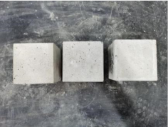 | 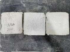 |
| 0.30–0(20)–400 °C | 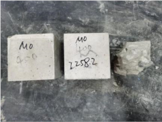 | 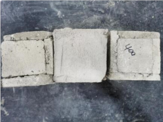 |
| 0. 30–0(20)–600 °C | 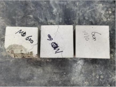 | 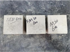 |
| 0.30–0(20)–800 °C | 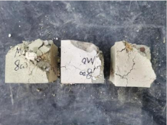 |  |
| 0.35–0(20)–200 °C | 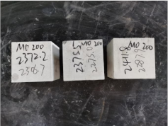 | 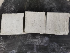 |
| 0.35–0(20)–400 °C | 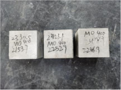 |  |
| 0.35–0(20)–600 °C |  | 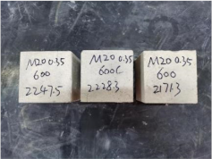 |
| 0.35–0(20)–800 °C | 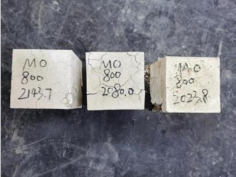 | 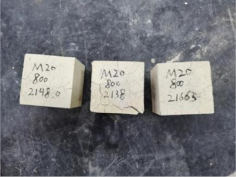 |
| 0.40–0(20)–200 °C |  | 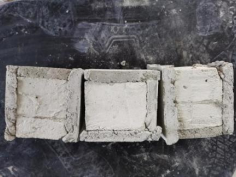 |
| 0.40–0(20)–400 °C | 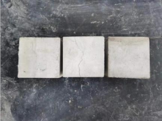 |  |
| 0.40–0(20)–600 °C |  |  |
| 0.40–0(20)–800 °C |  | 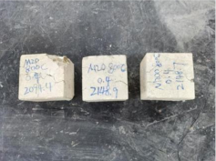 |
Publisher’s Note: MDPI stays neutral with regard to jurisdictional claims in published maps and institutional affiliations. |
© 2022 by the authors. Licensee MDPI, Basel, Switzerland. This article is an open access article distributed under the terms and conditions of the Creative Commons Attribution (CC BY) license (https://creativecommons.org/licenses/by/4.0/).
Share and Cite
Liu, C.; Chen, J. High Temperature Degradation Mechanism of Concrete with Plastering Layer. Materials 2022, 15, 398. https://doi.org/10.3390/ma15020398
Liu C, Chen J. High Temperature Degradation Mechanism of Concrete with Plastering Layer. Materials. 2022; 15(2):398. https://doi.org/10.3390/ma15020398
Chicago/Turabian StyleLiu, Chihao, and Jiajian Chen. 2022. "High Temperature Degradation Mechanism of Concrete with Plastering Layer" Materials 15, no. 2: 398. https://doi.org/10.3390/ma15020398
APA StyleLiu, C., & Chen, J. (2022). High Temperature Degradation Mechanism of Concrete with Plastering Layer. Materials, 15(2), 398. https://doi.org/10.3390/ma15020398