
The Effect of Coatings on Cutting Force in Turning of C45 Steel


Abstract
:1. Introduction
2. Cutting Force Model
2.1. Force Decomposition in Turning
2.2. Proposal of Methodology for Cutting Force Prediction
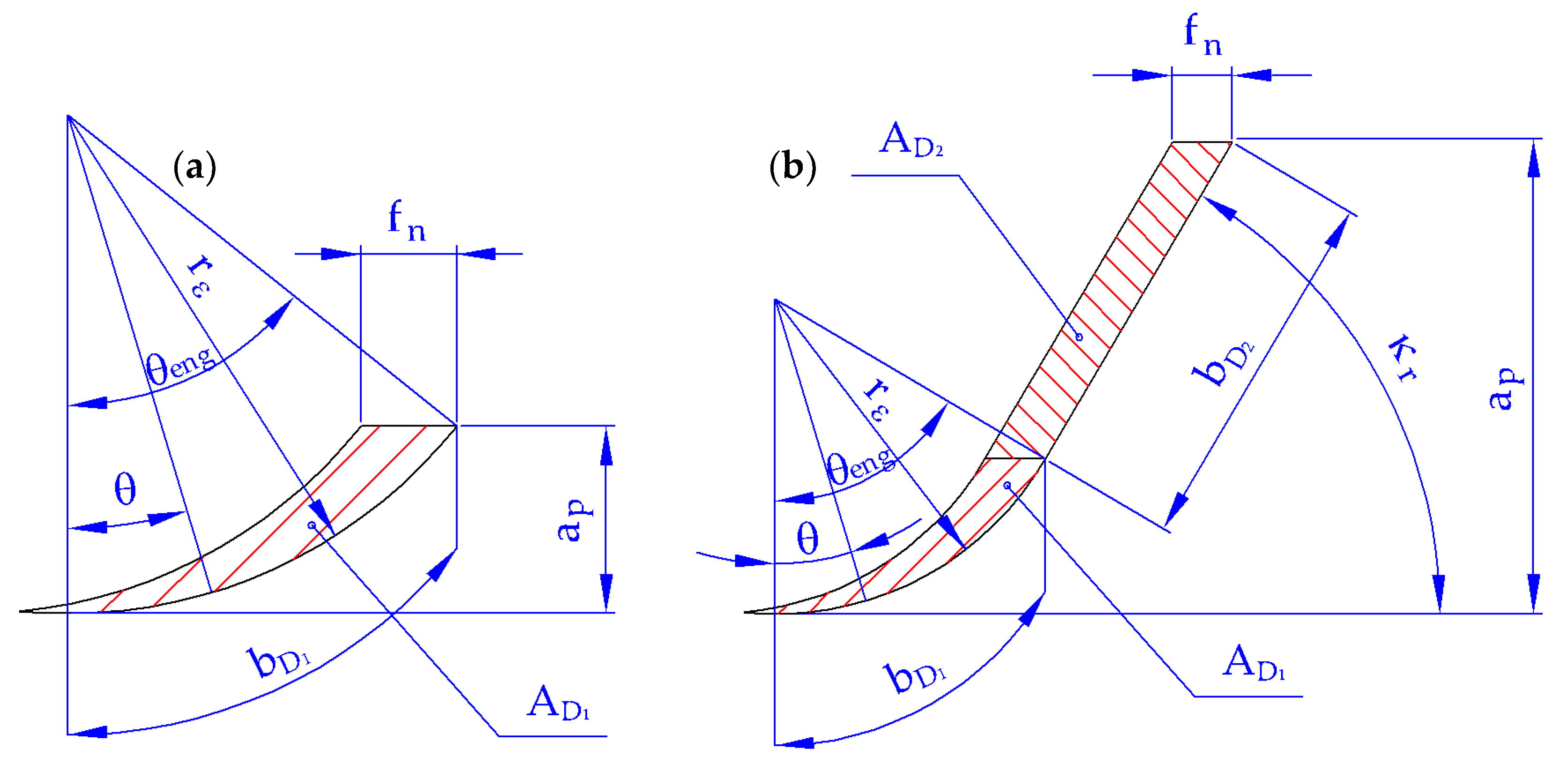
2.3. Rounded Part of the Cutting Edge
2.4. Straight Part of the Cutting Edge
2.5. Resultant Equations for the Cutting Force Calculation
3. Design of Experiments
3.1. Machine Tool
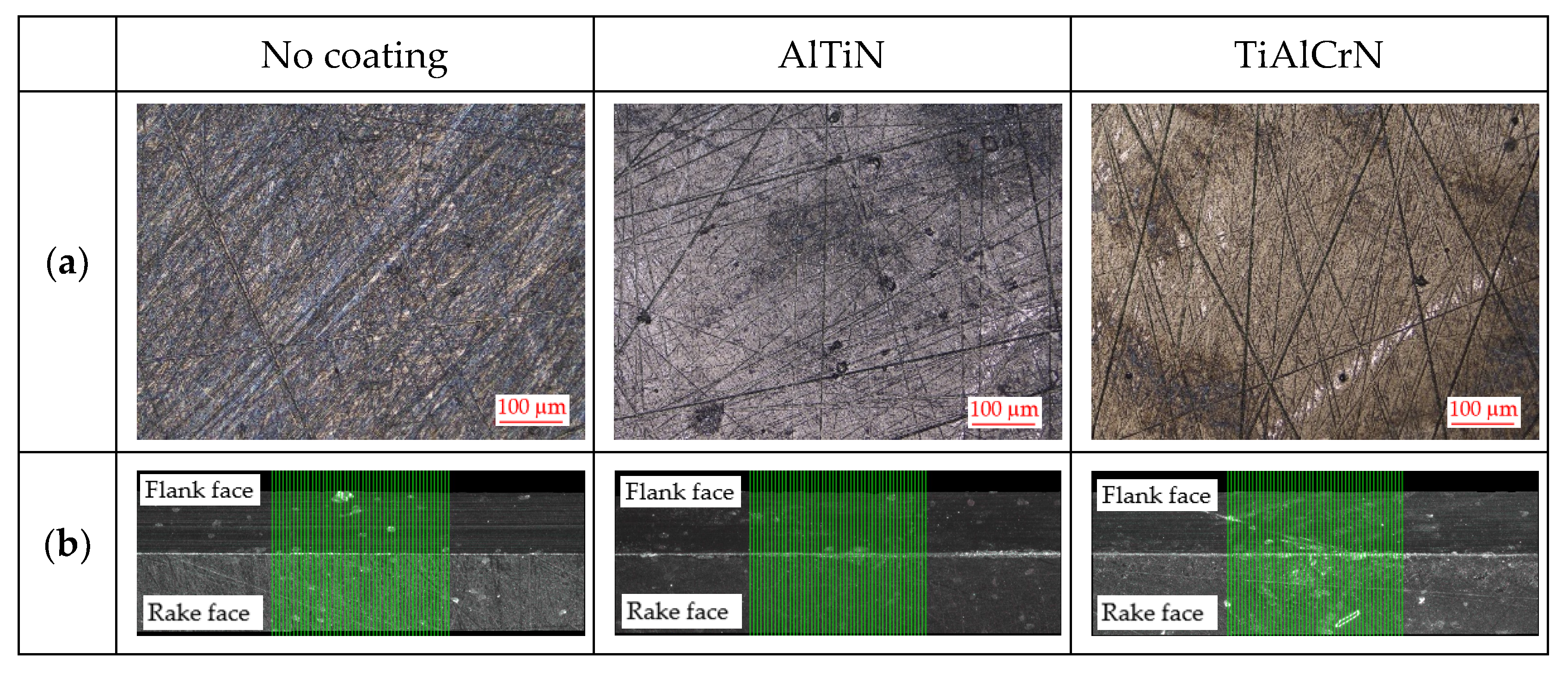
3.2. Cutting Tool
3.3. Workpiece
3.4. Measuring Devices
3.5. Design of Experiments for Uncoated and Coated Cutting Tools
4. Results and Discussions
4.1. Accuracy of the Proposed Mathematical Model for Uncoated Cutting Tools
4.2. Comparing the Experimental Cutting Force Values of Uncoated and Coated Cutting Tools
4.3. Determining the Coating Correction Factor
4.4. Accuracy of the Proposed Mathematical Model for Coated Cutting Tools
5. Conclusions
- In the comparison of the experimental cutting force data for the uncoated and coated inserts, there was a statistically significant difference resulting from the paired t-test p-values (no coating–AlTiN: p-value = 0.011; no coating–TiAlCrN: p-value = 0.024), which were below the confidence level (α = 0.05); see Table 9. The percentage difference was found to be up to 4%;
- In the comparison of the experimental cutting force data for the two coated inserts, there was no statistically significant difference resulting from the paired t-test p-value (p-value = 0.392), which was above the confidence level (α = 0.05); see Table 9. This was despite the fact that the measured properties of the coatings were slightly different. The percentage difference was up to 1%;
- As there was no statistically significant difference between the two coated inserts, a linear regression was found for a coating correction factor that was valid for the two researched coatings, i.e., AlTiN and TiAlCrN. This regression included the impact of the feed per revolution as well as the cutting speed, which were statistically significant parameters according to the analysis of variance p-values (fn: p-value = 0.003; vc: p-value = 0.017), which were below the confidence level (α = 0.05); see Table 12;
- When the calculated cutting force data, which included the coating correction factor, were compared with the experimental data of the coated inserts, there was no statistically significant difference resulting from the paired t-test p-values (Model–AlTiN: p-value = 0.234; Model–TiAlCrN: p-value = 0.374), which were above the confidence level (α = 0.05); see Table 14. The percentage difference was found to be up to 0.6%.
Author Contributions
Funding
Institutional Review Board Statement
Informed Consent Statement
Data Availability Statement
Conflicts of Interest
Nomenclature
| (%) | Percentage deviation between experimental and calculated cutting force values |
| (°) | Clearance angle |
| (°) | Wedge angle |
| (°) | Rake angle |
| (°) | Actual value of engagement angle of the rounded part of the cutting edge |
| (°) | Engagement angle of the rounded part of the cutting edge |
| (°) | Lead angle |
| (°) | Inclination angle |
| (-) | No unit factor for DOE that corresponds to the feed per revolution |
| (mm2) | Undeformed chip area |
| (mm2) | Undeformed chip area of the rounded part of the cutting edge |
| (mm2) | Undeformed chip area of the straight part of the cutting edge |
| (mm) | Depth of cut |
| (-) | No unit factor for DOE that corresponds to the cutting speed |
| (mm) | Undeformed chip width |
| (mm) | Undeformed chip width of the rounded part of the cutting edge |
| (mm) | Undeformed chip width of the straight part of the cutting edge |
| (N) | Resultant force |
| (N) | Cutting force |
| (N) | Cutting force of the rounded part of the cutting edge |
| (N) | Cutting force of the straight part of the cutting edge |
| (N) | Cutting force evaluated from experiment |
| (N) | Feed force |
| (N) | Passive force |
| (mm) | Feed per revolution |
| (mm) | Undeformed chip thickness |
| (mm) | Undeformed chip of the rounded part of the cutting edge |
| (mm) | Undeformed chip thickness of the straight part of the cutting edge |
| (-) | Correction factor of coating |
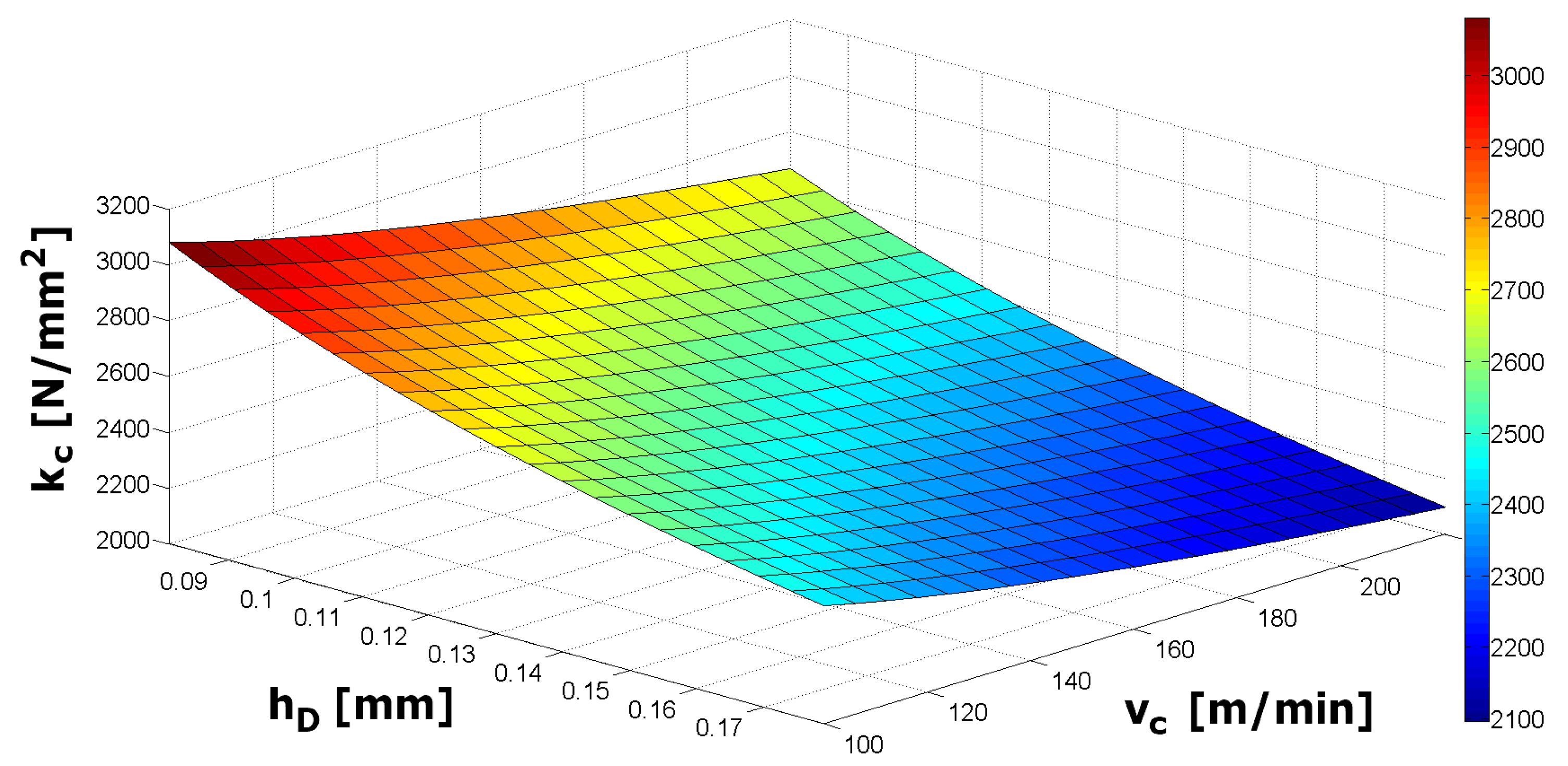
| (N/mm2) | Specific cutting force |
| (N/mm2) | Specific cutting force of the rounded part of the cutting edge |
| (N/mm2) | Specific cutting force of the straight part of the cutting edge |
| (N/mm2) | Specific cutting force for an undeformed chip area of 1 mm2 |
| (-) | Empirical constant that indicates the impact of the chip thickness on the specific cutting force |
| (-) | Empirical constant that indicates the impact of the cutting speed on the specific cutting force |
| (mm) | Cutting edge radius |
| (mm) | Nose radius |
| (N) | Standard deviation of the cutting force |
| (mm/min) | Feed rate speed |
| (m/min) | Cutting speed |
| (m/min) | Cutting speed of the centre point |
References
- Leyendecker, T.; Lemmer, O.; Esser, S.; Ebberink, J. The development of the PVD coating TiAlN as a commercial coating for cutting tools. Surf. Coat. Technol. 1991, 48, 175–178. [Google Scholar] [CrossRef]
- Tobota, D.; Chechowski, K.; Wronska, I.; Letocha, A.; Miller, T. The effects of the coating stripping process on regenerated tool cutting edges. J. Achiev. Mater. Manuf. Eng. 2013, 61, 294–301. [Google Scholar]
- Sivam, S.; Loganathan, G.; Saravanan, K.; RajendraKumar, S. Outcome of the Coating Thickness on the Tool Act and Process Parameters When Dry Turning Ti–6Al–4V Alloy: GRA Taguchi & ANOVA. Int. J. Innov. Technol. Explor. Eng. 2019, 8, 419–423. [Google Scholar]
- Keblouti, O.; Boulanouar, L.; Aziz, M.; Yellese, M. Effects of coating material and cutting parameters on the surface roughness and cutting forces in dry turning of AISI 52100 steel. Struct. Eng. Mech. 2017, 61, 519–526. [Google Scholar] [CrossRef]
- Jindal, P.; Santhanam, A.; Schleinkofer, U.; Shuster, A. Performance of PVD TiN, TiCN, and TiAlN coated cemented carbide tools in turning. Int. J. Refract. Met. Hard Mater. 1999, 17, 163–170. [Google Scholar] [CrossRef]
- Fernández-Abia, A.; Barreiro, J.; Fernández-Larrinoa, J.; López de Lacalle, L.; Fernández-Valdivielso, A.; Pereira, O. Behaviour of PVD coatings in the turning of austenitic stainless steels. Procedia Eng. 2013, 63, 133–141. [Google Scholar] [CrossRef] [Green Version]
- Venkatesh, V.; Ye, C.; Quinto, D.; Hoy, D. Performance Studies of Uncoated, CVD-Coated and PVD-Coated Carbides in Turning and Milling. CIRP Ann. 1991, 40, 545–550. [Google Scholar] [CrossRef]
- Wang, J. The effect of the multi-layer surface coating of carbide inserts on the cutting forces in turning operations. J. Mater. Process. Technol. 2000, 97, 114–119. [Google Scholar] [CrossRef]
- Kulkarni, A.; Sargade, V. Characterization and Performance of AlTiN, AlTiCrN, TiN/TiAlN PVD Coated Carbide Tools While Turning SS 304. Mater. Manuf. Process. 2015, 30, 748–755. [Google Scholar] [CrossRef]
- Kamely, M.; Noordin, M. The Impact of Cutting Tool Materials on Cutting Force. World Acad. Sci. Eng. Technol. 2011, 51, 903–906. [Google Scholar]
- Bach, P.; Trmal, G.; Zeman, P.; Vana, J.; Maly, J. High Performance Titanium Milling at Low Cutting Speed. In Proceedings of the 5th CIRP Conference on High Performance Cutting, Zurich, Switzerland, 4–7 June 2012; Elsevier B.V.: Amsterdam, Switzerland, 2012; pp. 226–231. [Google Scholar]
- Arrazola, P.; Özel, T.; Umbrello, D.; Davies, M.; Jawahir, I. Recent advances in modelling of metal machining processes. CIRP Ann. 2013, 62, 695–718. [Google Scholar] [CrossRef]
- Galanis, N.; Manolakos, D. Finite Element Analysis of the Cutting Forces in Turning of Femoral Heads from AISI 316L Stainless Steel. In Proceedings of the World Congress on Engineering 2014, London, UK, 2–4 July 2014; Volume II. [Google Scholar]
- Parihar, R.; Sahu, R.; Srinavasu, G. Finite Element Analysis of Cutting Forces Generated in Turning Process using Deform 3D Software. Mater. Today Proc. 2017, 4, 8432–8438. [Google Scholar] [CrossRef]
- Kumar, S.C.; Zeman, P.; Polcar, T. A 2D finite element approach for predicting the machining performance of nanolayered TiAlCrN coating on WC-Co cutting tool during dry turning of AISI 1045 steel. Ceram. Int. 2020, 46, 25073–25088. [Google Scholar] [CrossRef]
- Kara, F.; Aslantas, K.; Cicek, A. ANN and multiple regression method-based modelling of cutting forces in orthogonal machining of AISI 316L stainless steel. Neural Comput. Appl. 2015, 26, 237–250. [Google Scholar] [CrossRef]
- Qasim, M. Prediction of Cutting Force in Turning Process by Using Artificial Neural Network. Al-Khwarizmi Eng. J. 2019, 2, 34–46. [Google Scholar]
- Mia, M.; Khan, A.; Dhar, N. Study of surface roughness and cutting forces using ANN, RSM, and ANOVA in turning of Ti-6Al-4Vunder cryogenic jets applied at flank and rake faces of coated WC tool. Int. J. Adv. Manuf. Technol. 2017, 93, 975–991. [Google Scholar] [CrossRef]
- Noordin, M.; Venkatesh, V.; Sharif, S.; Elting, S.; Abdullah, A. Application of response surface methodology in describing the performance of coated carbide tools when turning AISI 1045 steel. J. Mater. Process. Technol. 2004, 145, 46–58. [Google Scholar] [CrossRef] [Green Version]
- Kolar, P.; Fojtu, P.; Shmitz, T. On Cutting force Coefficient Model with Respect to Tool Geometry and Tool Wear. Procedia Manuf. 2015, 1, 708–720. [Google Scholar] [CrossRef] [Green Version]
- Shalaby, M.; El Hakim, M.; Veldhuis, S.; Dosbaeva, G.K. An investigation into the behavior of the cutting forces in precision turning. Int. J. Adv. Manuf. Technol. 2017, 90, 1605–1615. [Google Scholar] [CrossRef]
- Stachurski, W.; Midera, S.; Kruszynski, B. Determination of Mathematical Formulae for the Cutting Force Fc during the Turning of C45 Steel. Mech. Mech. Eng. 2012, 16, 73–79. [Google Scholar]
- Mahmud, S.; Islam, K.; Habib, A.; Hossain, S.; Hoassain, M. Optimization of Turning Parameters for Cutting Force and Chip Optimization of Turning Parameters for Cutting Force and Chip. In Proceedings of the International Conference on Mechanical, Industrial and Materials Engineering 2015, Rajshahi, Bangladesh, 11–13 December 2015. [Google Scholar]
- Altintas, Y. Manufacturing Automation: Metal Cutting Mechanics, Machine Tool; Cambridge University Press: New York, NY, USA, 2012. [Google Scholar]
- Cascóna, I.; Sarasuaa, J. Mechanistic model for prediction of cutting forces in turning of non-axisymmetric parts. Procedia CIRP 2015, 31, 435–440. [Google Scholar] [CrossRef] [Green Version]
- Kienzle, O. Die Bestimmung von Kräften und Leistungen an spanenden Werkzeugen und Werkzeugmaschinen. VDI-Z 1952, 94, 299–305. [Google Scholar]
- Salehi, M.; Schmitz, T.; Copenhaver, R.; Haas, R.; Ovtcharova, J. Probabilistic Prediction of Cutting and Ploughing Forces using Extended Kienzle Force model in Orthogonal Turning Process. Procedia CIRP 2018, 77, 90–93. [Google Scholar] [CrossRef]
- Popovic, M.; Tanovic, L.; Ehmann, K. Cutting Forces Prediction: The Experimental Identification of Orthogonal Cutting Coefficients. FME Trans. 2017, 45, 459–467. [Google Scholar] [CrossRef] [Green Version]
- Bera, T.; Manikandan, H.; Bansal, A.; Nema, D. A Method to Determine Cutting Force Coefficients in Turning Using Mechanistic Approach. Int. J. Mater. Mech. Manuf. 2018, 6, 99–103. [Google Scholar]
- Horváth, R.; Lukács, J. Application of a Force Model Adapted for the Precise Turning of Various Metallic Materials. J. Mech. Eng. 2017, 63, 489–500. [Google Scholar] [CrossRef] [Green Version]
- Kovalčík, J.; Zeman, P.; Holešovský, F.; Mádl, J.; Kučerová, L. Cutting force modelling with effects of cutting tool geometry and tool wear in milling of DIN C45 steel. MM Sci. J. 2020. [Google Scholar] [CrossRef]
- Bartoszuk, M.; Grzesik, W. Investigation of initial wear period of differently coated carbide cutting tools. J. Mach. Eng. 2015, 15, 37–45. [Google Scholar]


| Parameter | Unit | Symbol | No Coating | Coating | |
|---|---|---|---|---|---|
| AlTiN | TiAlCrN | ||||
| Cutting edge radius | μm | r | 8.94 ± 0.67 | 10.45 ± 1.28 | 11.42 ± 0.58 |
| Surface roughness | μm | Ra | 0.13 | 0.16 | 0.24 |
| Clearance angle | ° | αo | 11 | 11 | 11 |
| Wedge angle | ° | βo | 79 | 79 | 79 |
| Rake angle | ° | γo | 0 | 0 | 0 |
| Property | Unit | Symbol | AlTiN | TiAlCrN |
|---|---|---|---|---|
| Coating thickness | μm | h | 2.2 | 4.3 |
| Hardness | GPa | H | 23.8 ± 3.32 | 19.8 ± 1.9 |
| Young’s modulus | GPa | E | 685 ± 25.1 | 469 ± 21.2 |
| Chemical composition | % | Ti | 24.4 ± 0.14 | 13.3 ± 0.14 |
| % | Al | 24 ± 0.03 | 14.8 ± 0.03 | |
| % | Cr | - | 24.3 ± 0.06 | |
| % | N | 51.6 ± 0.07 | 47.5 ± 0.27 |
| Parameter | Unit | Symbol | Levels | ||||
|---|---|---|---|---|---|---|---|
| −α | −1 | 0 | +1 | +α | |||
| Feed per revolution | mm | fn | 0.103 | 0.12 | 0.16 | 0.20 | 0.217 |
| Cutting speed | m/min | vc | 103 | 120 | 160 | 200 | 217 |
| Depth of cut | mm | ap | 2 | ||||
| Type of Points | No Unit Parameters | Cutting Conditions | ||
|---|---|---|---|---|
| A | B | fn (mm) | vc (m/min) | |
| Cube points | −1 | −1 | 0.12 | 120 |
| +1 | −1 | 0.20 | 120 | |
| −1 | +1 | 0.12 | 200 | |
| +1 | +1 | 0.20 | 200 | |
| Axial points | −α | 0 | 0.103 | 160 |
| +α | 0 | 0.217 | 160 | |
| 0 | −α | 0.16 | 103 | |
| 0 | +α | 0.16 | 217 | |
| Centre point | 0 | 0 | 0.16 | 160 |
| Cutting Conditions | Results | ||
|---|---|---|---|
| fn (mm) | vc (m/min) | Fc (N) | SD (N) |
| 0.12 | 120 | 679.5 | 1.3 |
| 0.20 | 120 | 952.4 | 2.7 |
| 0.12 | 200 | 604.8 | 3.3 |
| 0.20 | 200 | 887.3 | 0.1 |
| 0.103 | 160 | 581.5 | 0.6 |
| 0.217 | 160 | 977.7 | 0.8 |
| 0.16 | 103 | 847.1 | 1.4 |
| 0.16 | 217 | 740.2 | 0.5 |
| 0.16 | 160 | 782.9 | 0.3 |
| Cutting Conditions | Results | |||
|---|---|---|---|---|
| fn (mm) | vc (m/min) | Fc exp (N) | AD (mm2) | kc (N/mm2) |
| 0.12 | 120 | 679.5 | 0.240 | 2831 |
| 0.20 | 120 | 952.4 | 0.400 | 2381 |
| 0.12 | 200 | 604.8 | 0.240 | 2520 |
| 0.20 | 200 | 887.3 | 0.400 | 2218 |
| 0.103 | 160 | 581.5 | 0.206 | 2823 |
| 0.217 | 160 | 977.7 | 0.434 | 2253 |
| 0.16 | 103 | 547 | 0.320 | 2647 |
| 0.16 | 217 | 740.2 | 0.320 | 2313 |
| 0.16 | 160 | 782.9 | 0.320 | 2446 |
| Mean | SD | SE Mean | 95% CI for μ_Difference | T-Value | p-Value |
|---|---|---|---|---|---|
| 0.20 | 7.71 | 2.57 | (−5.72; 6.13) | 0.08 | 9.39 × 10⁻¹ |
| Cutting Conditions | No Coating | AlTiN | TiAlCrN | ||||
|---|---|---|---|---|---|---|---|
| fn (mm) | vc (m/min) | Fc (N) | SD (N) | Fc (N) | SD (N) | Fc (N) | SD (N) |
| 0.12 | 120 | 679.5 | 1.3 | 652.2 | 1.9 | 653.7 | 1.2 |
| 0.20 | 120 | 952.4 | 2.7 | 944.9 | 1.5 | 942.1 | 1.0 |
| 0.12 | 200 | 604.8 | 3.3 | 595.8 | 4.2 | 602.2 | 1.7 |
| 0.20 | 200 | 887.3 | 0.1 | 867.3 | 2.3 | 874.3 | 2.2 |
| 0.16 | 160 | 782.9 | 0.3 | 762.4 | 1.1 | 760.2 | 0.1 |
| Data to Compare | Mean | SD | SE Mean | 95% CI for μ_Difference | T-Value | p-Value |
|---|---|---|---|---|---|---|
| No coating–AlTiN | 16.86 | 8.39 | 3.75 | (6.44; 27.28) | 4.49 | 1.10 × 10⁻² |
| No coating–TiAlCrN | 14.88 | 9.40 | 4.21 | (3.20; 26.56) | 3.54 | 2.40 × 10⁻² |
| AlTiN–TiAlCrN | −1.98 | 4.61 | 2.06 | (−7.71; 3.75) | −0.96 | 39.20 × 10⁻² |
| Cutting Conditions | Fc (N) | KCoating (-) | ||||
|---|---|---|---|---|---|---|
| fn (mm) | vc (m/min) | Model | Experiment | AlTiN | TiAlCrN | |
| AlTiN | TiAlCrN | |||||
| 0.12 | 120 | 662.3 | 652.2 | 653.7 | 0.985 | 0.987 |
| 0.20 | 120 | 945.1 | 944.9 | 942.1 | 1 | 0.997 |
| 0.12 | 200 | 602.9 | 595.8 | 602.2 | 0.988 | 0.999 |
| 0.20 | 200 | 860.3 | 867.3 | 874.3 | 1.008 | 1.016 |
| 0.16 | 160 | 767.4 | 762.4 | 760.2 | 0.993 | 0.991 |
| Term | Coefficient | SE Coefficient | T-Value | p-Value |
|---|---|---|---|---|
| Constant | 9.44 × 10⁻¹ | 9.91 × 10⁻³ | 95.30 | 0.00 |
| fn | 1.95 × 10⁻¹ | 4.32 × 10⁻² | 4.50 | 0.30 × 10⁻² |
| vc | 1.34 × 10⁻⁴ | 4.30 × 10⁻⁵ | 3.10 | 1.70 × 10⁻² |
| Source | DF | Adj SS | Adj MS | F-Value | p-Value |
|---|---|---|---|---|---|
| Regression | 2 | 7.15 × 10⁻⁴ | 3.57 × 10⁻⁴ | 14.93 | 0.30 × 10⁻² |
| fn | 1 | 4.85 × 10⁻⁴ | 4.85 × 10⁻⁴ | 20.24 | 0.30 × 10⁻² |
| vc | 1 | 2.30 × 10⁻⁴ | 2.30 × 10⁻⁴ | 9.62 | 1.70 × 10⁻² |
| Error | 7 | 1.68 × 10⁻⁴ | 0.24 × 10⁻⁴ | ||
| Lack of fit | 2 | 0.67 × 10⁻⁴ | 0.34 × 10⁻⁴ | 1.68 | 27.70 × 10⁻² |
| Pure error | 5 | 1.00 × 10⁻⁴ | 0.20 × 10⁻⁴ | ||
| Total | 9 | 8.82 × 10⁻⁴ |
| Cutting Conditions | Fc (N) | |||
|---|---|---|---|---|
| fn (mm) | vc (m/min) | Model | Experiment | |
| AlTiN | TiAlCrN | |||
| 0.12 | 120 | 651.4 | 652.2 | 653.7 |
| 0.20 | 120 | 944.2 | 944.9 | 944.2 |
| 0.12 | 200 | 599.4 | 595.8 | 599.4 |
| 0.20 | 200 | 868.8 | 867.3 | 868.8 |
| 0.16 | 160 | 764.9 | 762.4 | 764.9 |
| Data to Compare | Mean | SD | SE Mean | 95% CI for μ_Difference | T-Value | p-Value |
|---|---|---|---|---|---|---|
| Model–AlTiN | 1.22 | 1.95 | 0.97 | (−1.196; 3.636) | 1.40 | 2.34 × 10⁻¹ |
| Model–TiAlCrN | −0.46 | 1.03 | 0.46 | (−1.737; 0.817) | −1.00 | 3.74 × 10⁻¹ |
Publisher’s Note: MDPI stays neutral with regard to jurisdictional claims in published maps and institutional affiliations. |
© 2022 by the authors. Licensee MDPI, Basel, Switzerland. This article is an open access article distributed under the terms and conditions of the Creative Commons Attribution (CC BY) license (https://creativecommons.org/licenses/by/4.0/).
Share and Cite
Kovalčík, J.; Mašek, P.; Malý, J.; Kožmín, P.; Syrovátka, J. The Effect of Coatings on Cutting Force in Turning of C45 Steel. Materials 2022, 15, 590. https://doi.org/10.3390/ma15020590
Kovalčík J, Mašek P, Malý J, Kožmín P, Syrovátka J. The Effect of Coatings on Cutting Force in Turning of C45 Steel. Materials. 2022; 15(2):590. https://doi.org/10.3390/ma15020590
Chicago/Turabian StyleKovalčík, Jaroslav, Petr Mašek, Jan Malý, Pavel Kožmín, and Jiří Syrovátka. 2022. "The Effect of Coatings on Cutting Force in Turning of C45 Steel" Materials 15, no. 2: 590. https://doi.org/10.3390/ma15020590