
Development and Characterisation of Joints with Novel Densified and Wood/Cork Composite Substrates
 , and
, and 
Abstract
:1. Introduction
2. Experimental Details
2.1. Materials
2.1.1. Wood
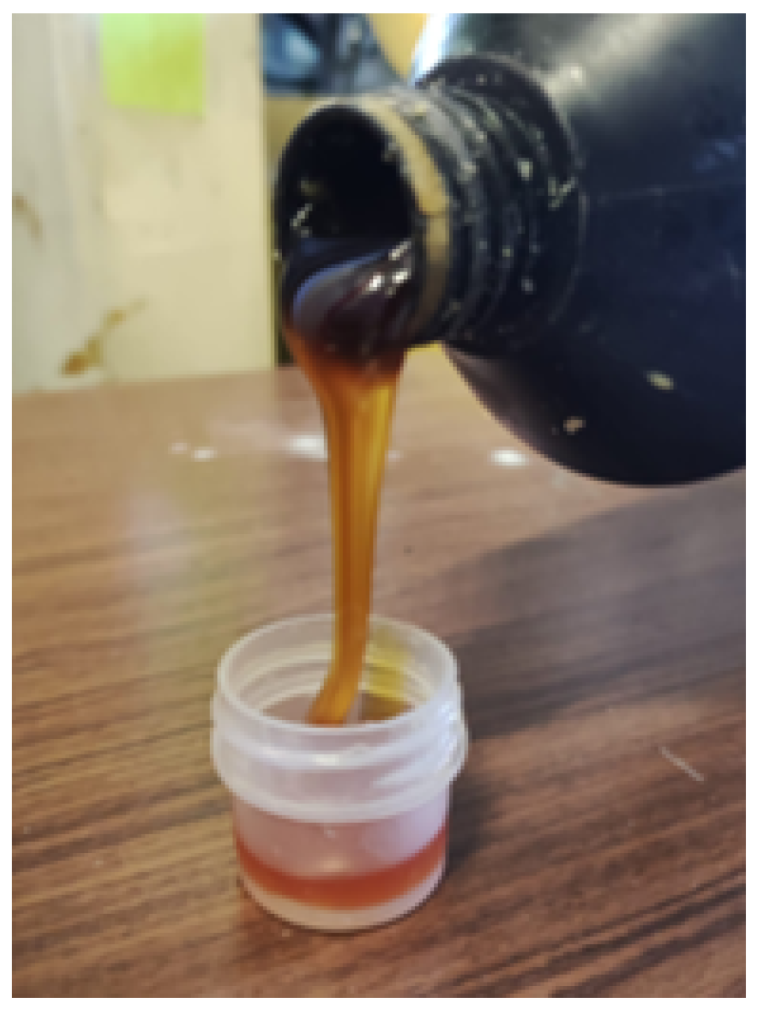
2.1.2. Bio-Adhesive
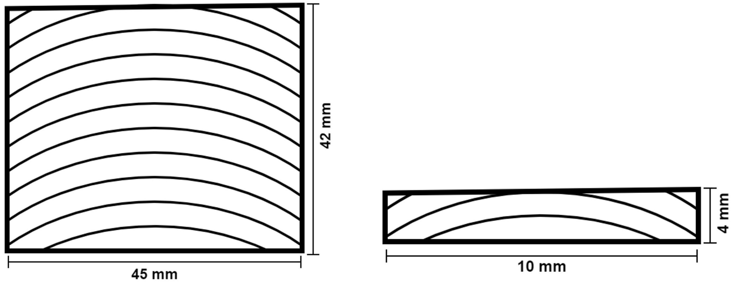
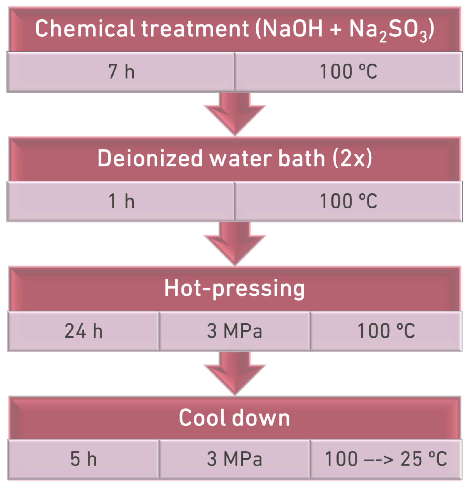
2.2. Densification Process
2.2.1. Chemical Treatment
2.2.2. Thermo-Mechanical Treatment
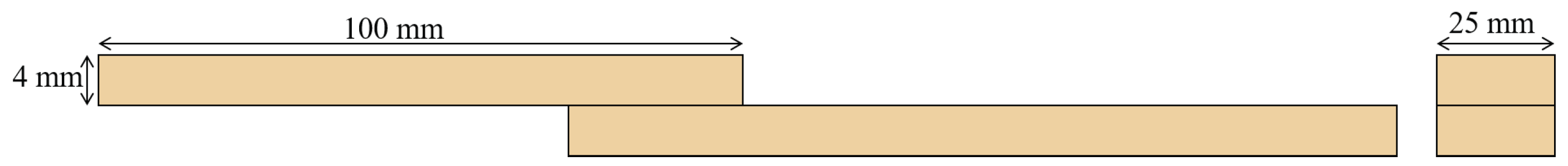
2.3. Joint Manufacturing

2.4. Testing Conditions
3. Experimental Results and Discussion
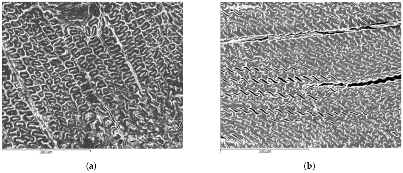
3.1. Densification Process
3.2. Effect of the Overlap Length on Failure Load and Energy Absorbed
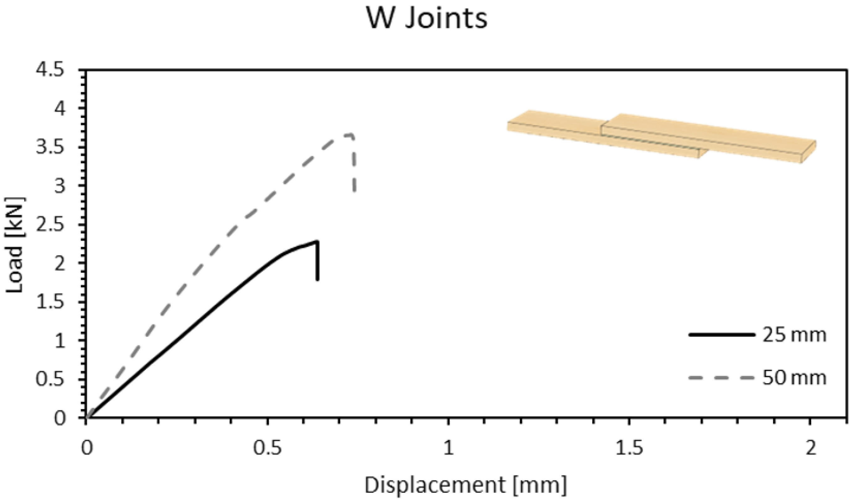
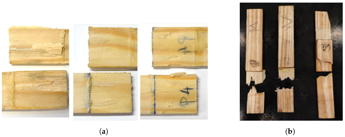
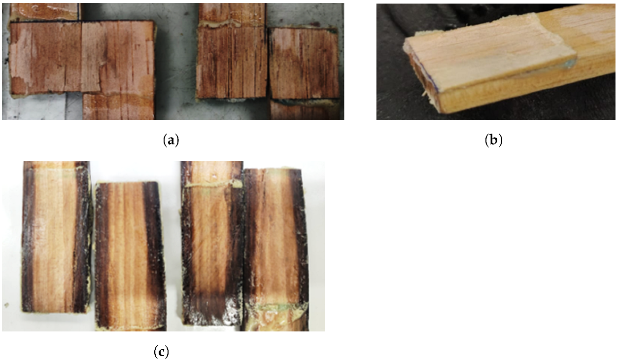
3.2.1. Wood–Wood Joints (W)
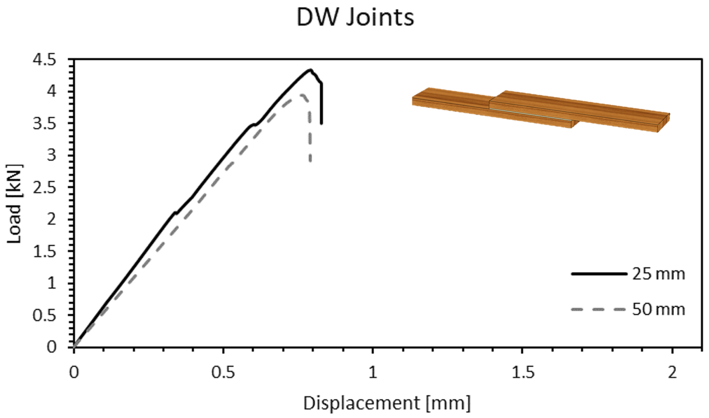
3.2.2. Densified Wood–Densified Wood Joints (DW)
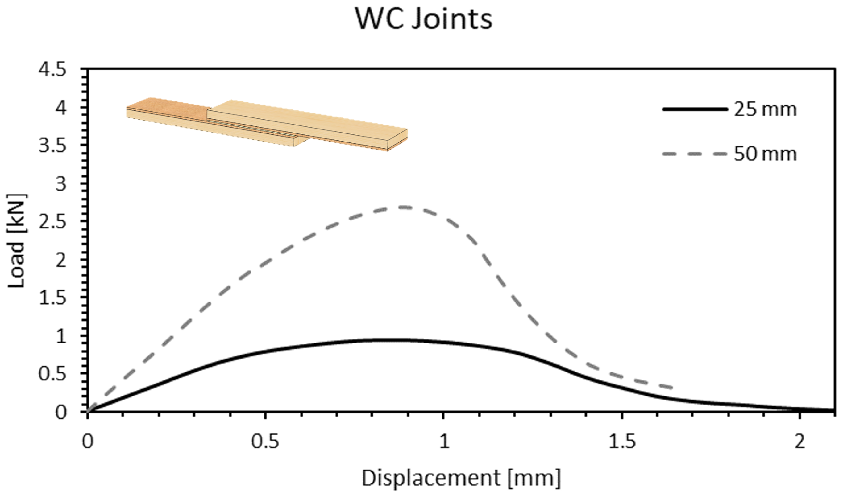
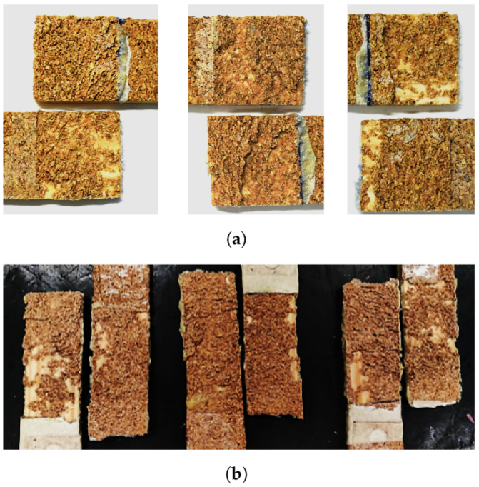
3.2.3. Wood/Cork—Cork/Wood Joints (WC)
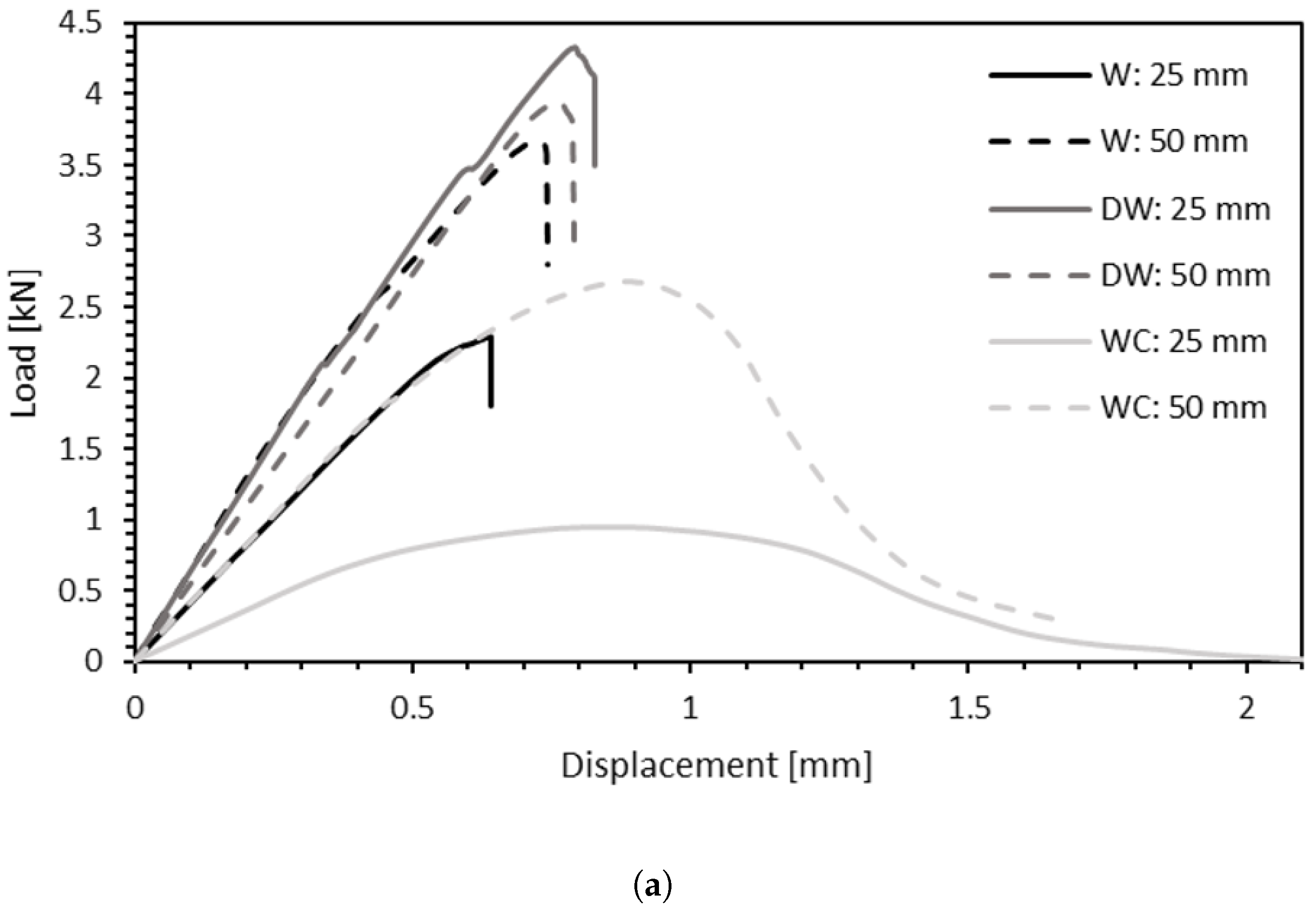
3.2.4. Comparison between Different Substrates and Different Overlap Lengths
3.3. Effect of the Testing Rate on Failure Load and Energy Absorption
3.3.1. Wood–Wood Joints (W)
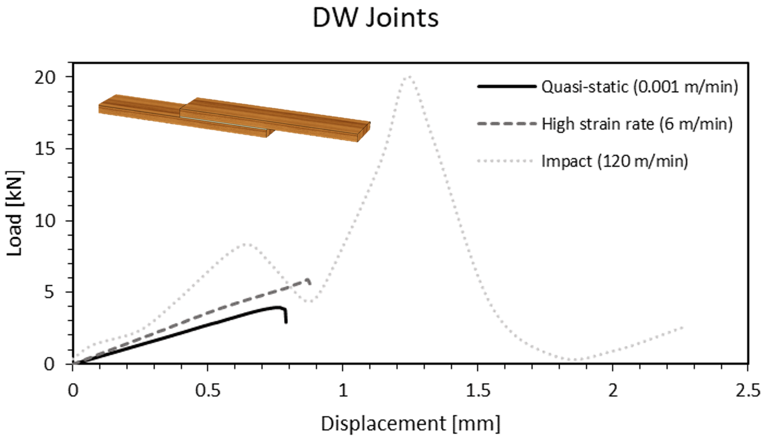
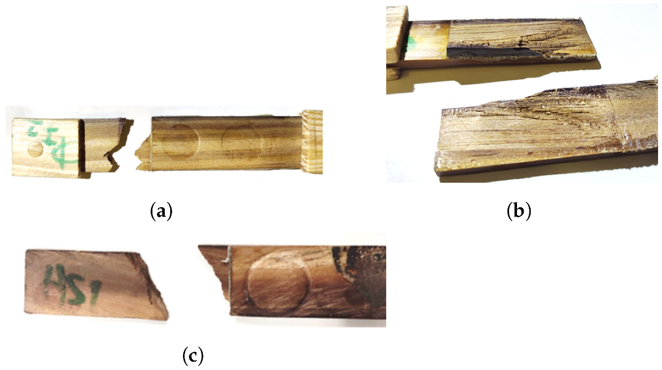
3.3.2. Densified Wood—Densified Wood Joints (DW)
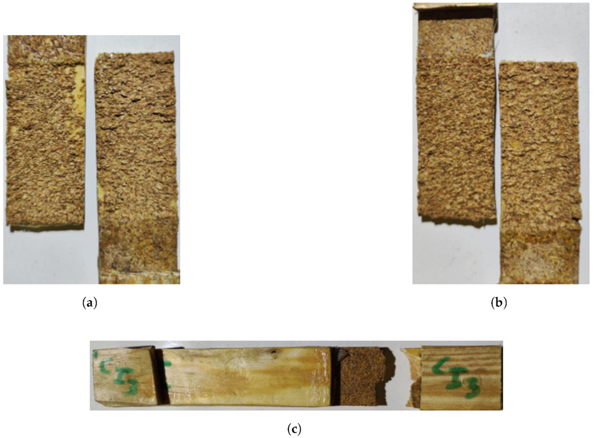
3.3.3. Wood/Cork–Cork/Wood Joints (WC)
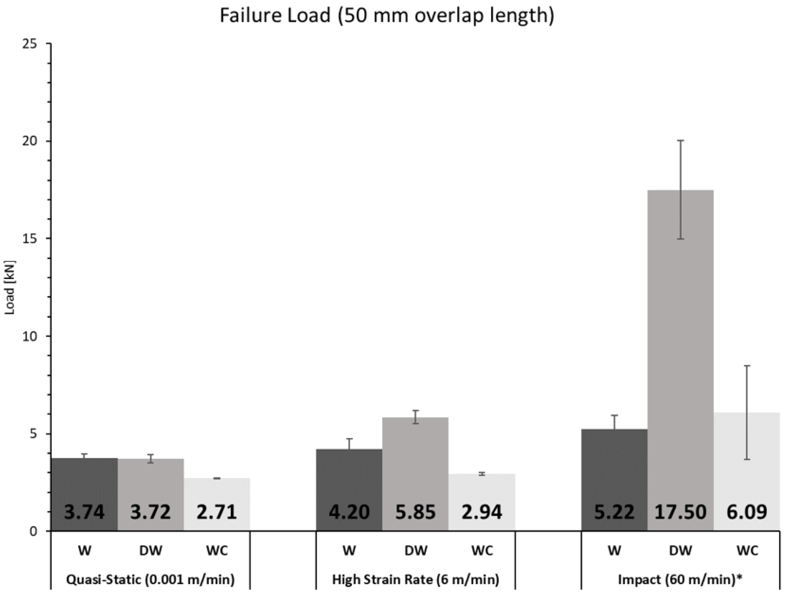
3.3.4. Comparison between Different Testing Rates
4. Numerical Analysis
4.1. General Considerations
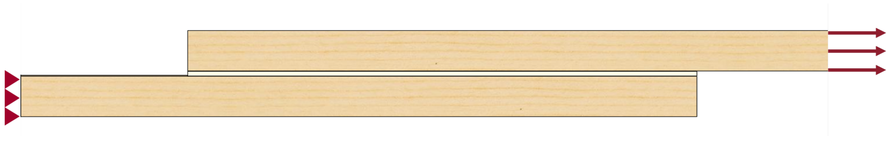
4.2. Boundary Conditions
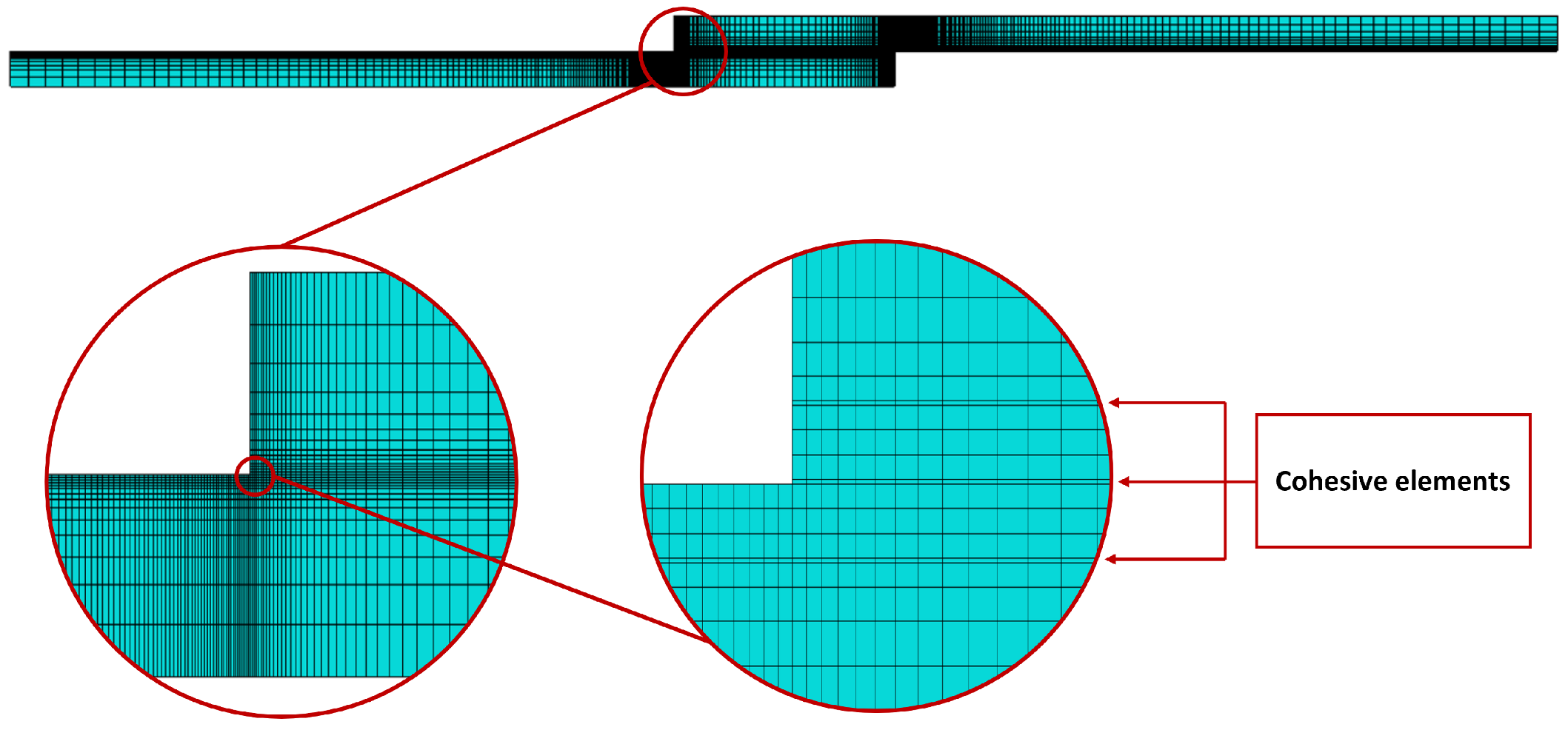
4.3. Mesh
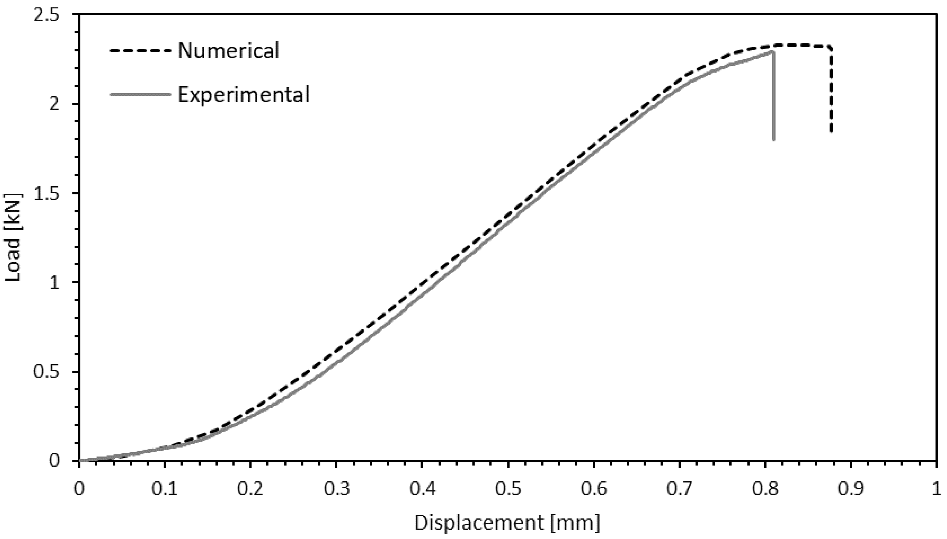
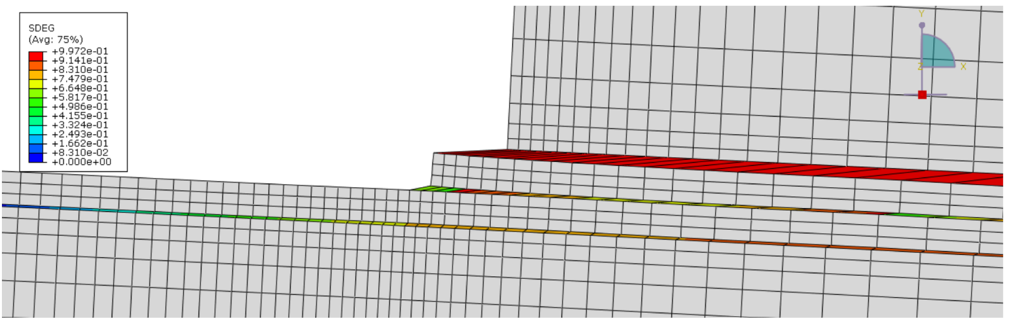
Numerical Results
5. Conclusions
Author Contributions
Funding
Institutional Review Board Statement
Informed Consent Statement
Data Availability Statement
Conflicts of Interest
References
- da Silva, L.; Öchsner, A.; Adams, R. Handbook of Adhesion Technology; Springer: Berlin/Heidelberg, Germany, 2018. [Google Scholar]
- Bergman, R.; Cai, Z.; Carll, C.; Clausen, C.; Dietenberger, M.; Falk, R.; Frihart, C.; Glass, S.; Hunt, C.; Ibach, R.; et al. Wood Handbook: Wood as an Engineering Material; Forest Products Laboratory: Madison, WI, USA, 2010. [Google Scholar]
- Yang, H.; Gao, M.; Wang, J.; Mu, H.; Qi, D. Fast Preparation of high-performance wood materials assisted by ultrasonic and vacuum impregnation. Forests 2021, 12, 567. [Google Scholar] [CrossRef]
- Song, J.; Chaoji, C.; Zhu, S.; Zhu, M.; Dai, J.; Ray, U.; Li, Y.; Kuang, Y.; Li, Y.; Quispe, N.; et al. Processing bulk natural wood into a high-performance structural material. Nature 2018, 554, 224–228. [Google Scholar] [CrossRef] [PubMed]
- Kutnar, A.; Sernek, M. Densification of wood. Zb. Gozdarstva Lesar. 2007, 82, 53–62. [Google Scholar]
- Li, R.; Guo, X.; Ekevad, M.; Marklund, B.; Cao, P. Investigation of glueline shear strength of pine wood bonded with PVAc by response surface methodology. BioResources 2015, 10, 3831–3838. [Google Scholar] [CrossRef] [Green Version]
- do Nascimento, A.; Garcia, R.; Della Lucia, R. Adhesion quality of glued joints from different commercial wood species. Cerne 2013, 19, 593–601. [Google Scholar]
- Abrahão, C.; Varella, C.; Pinto, F.; Khoury Junior, K. Measuring wood failure percentage using a machine vision system. Rev. Árvore 2003, 27, 71–78. [Google Scholar] [CrossRef] [Green Version]
- Follrich, J.; Teischinger, A.; Gindl, W.; Müller, U. Adhesive bond strength of end grain joints in softwood with varying density. Holzforschung 2008, 62, 237–242. [Google Scholar] [CrossRef]
- Follrich, J.; Höra, M.; Müller, U.; Teischinger, A.; Gindl, W. Adhesive bond strength of end grain joints in balsa wood with different density. Wood Res. 2010, 55, 21–32. [Google Scholar]
- Wolcott, M.; Kamke, F.; Dillard, D. Fundamental aspects of wood deformation pertaining to manufacture of wood-based composites. Wood Fiber Sci. 1994, 54, 496–511. [Google Scholar]
- Morsing, N. Densification of wood. The Influence of Hygrothermal Treatment on Compression of Beech Perpendicular to the Grain; Series R; Department of Structural Engineering and Materials Technical University of Denmark: Lyngby, Denmark, 2000. [Google Scholar]
- Laine, K.; Belt, T.; Rautkari, L.; Ramsay, J.; Hill, C.; Hughes, M. Measuring the thickness swelling and set-recovery of densified and thermally modified Scots pine solid wood. J. Mater. Sci. 2013, 48, 8530–8538. [Google Scholar] [CrossRef]
- Schwarzkopf, M. Densified wood impregnated with phenol resin for reduced set-recovery. Wood Mater. Sci. Eng. 2021, 16, 35–41. [Google Scholar] [CrossRef]
- Sadatnezhad, S.; Khazaeian, A.; Sandberg, D.; Tabarsa, T. Continuous Surface Densification of Wood: A New Concept for Large-scale Industrial Processing. Bioresources 2017, 12, 3122–3132. [Google Scholar] [CrossRef] [Green Version]
- Laine, K.; Segerholm, K.; Wålinder, M.; Rautkari, L.; Hughes, M. Wood densification and thermal modification: Hardness, set-recovery and micromorphology. Wood Sci. Technol. 2016, 50, 883–894. [Google Scholar] [CrossRef]
- Shi, J.; Peng, J.; Huang, Q.; Cai, L.; Shi, S. Fabrication of densified wood via synergy of chemical pretreatment, hot-pressing and post mechanical fixation. J. Wood Sci. 2020, 66, 5. [Google Scholar] [CrossRef]
- Novel, D.; Ghio, S.; Gaiardo, A.; Picciotto, A.; Guidi, V.; Speranza, G.; Boscardin, M.; Bellutti, P.; Pugno, N. Strengthening of wood-like materials via densification and nanoparticle intercalation. Nanomaterials 2020, 10, 478. [Google Scholar] [CrossRef] [PubMed] [Green Version]
- Li, J.; Chen, C.; Zhu, J.; Ragauskas, A.; Hu, L. In situ wood delignification toward sustainable applications. Acc. Mater. Res. 2021, 2, 606–620. [Google Scholar] [CrossRef]
- Keplinger, T.; Wittel, F.; Rüggeberg, M.; Burgert, I. Wood Derived Cellulose Scaffolds—Processing and Mechanics. Adv. Mater. 2021, 33, 2001375. [Google Scholar] [CrossRef]
- Beaud, F.; Niemz, P.; Pizzi, A. Structure–property relationships in one-component polyurethane adhesives for wood: Sensitivity to low moisture content. J. Appl. Polym. Sci. 2006, 101, 4181–4192. [Google Scholar] [CrossRef]
- Richter, K.; Steiger, R. Thermal stability of wood-wood and wood-FRP bonding with polyurethane and epoxy adhesives. Adv. Eng. Mater. 2005, 7, 419–426. [Google Scholar] [CrossRef]
- Vasiliki, K.; Ioannis, B. Bondability of Black locust (Robinia pseudoacacia) and Beech wood (Fagus sylvatica) with polyvinyl acetate and polyurethane adhesives. Maderas. Ciencia y Tecnología 2017, 19, 87–94. [Google Scholar] [CrossRef] [Green Version]
- Barbosa, A.; da Silva, L.; Banea, M.; Öchsner, A. Methods to increase the toughness of structural adhesives with micro particles: An overview with focus on cork particles: Methoden zur Erhöhung der Zähigkeit von Strukturklebern mit Mikropartikeln: Ein Überblick mit dem Fokus auf Kork. Mater. Werkst. 2016, 47, 307–325. [Google Scholar] [CrossRef]
- Akhavan-Safar, A.; Barbosa, A.; da Silva, L.; Ayatollahi, M. Micro failure analysis of adhesively bonded joints enhanced with natural cork particles: Impact of overlap length and particles volume fraction. Frattura ed Integrità Strutturale 2018, 12, 266–274. [Google Scholar] [CrossRef] [Green Version]
- da Silva, C.; Barbosa, A.; Carbas, R.; Marques, E.; Akhavan-Safar, A.; da Silva, L. Influence of cork microparticles on the fracture type in single lap joints. Proc. Inst. Mech. Eng. Part C J. Mech. Eng. Sci. 2021, 235, 497–507. [Google Scholar] [CrossRef]
- de Moura, M.; Dourado, N. Wood Fracture Characterisation; Springer: Berlin/Heidelberg, Germany, 2018. [Google Scholar]
- ASTM D1002-99; Standard Test Method for Apparent Shear Strength of Single-Lap-Joint Adhesively Bonded Metal Specimens by Tension Loading (Metal-to-Metal). ASTM International: Pennsylvania, PA, USA, 2001.
- ISO 4587; Adhesives—Determination of Tensile Lap-Shear Strength of Rigid-to-Rigid Bonded Assemblies. International Organization for Standardization: Geneva, Switzerland, 2003.


| [GPa] | [GPa] | [GPa] | [GPa] | [GPa] | [GPa] | |||
|---|---|---|---|---|---|---|---|---|
| 12.0 | 1.91 | 1.01 | 0.51 | 0.47 | 0.31 | 1.12 | 1.04 | 0.29 |
| [MPa] | [MPa] | [MPa] | [MPa] | [MPa] | [MPa] |
|---|---|---|---|---|---|
| 97.5 | 7.9 | 4.2 | 16.0 | 16.0 | 4.5 |
| Q-S (0.001 m/min) | HCR (6 m/min) | Impact (60 m/min) | |
|---|---|---|---|
| W | 25 | 50 | 50 |
| 50 | |||
| DW | 25 | 50 | 50 |
| 50 | |||
| WC | 25 | 50 | 50 |
| 50 |
| Initial Density [g/] | Final Density [g/] | Increase | |
|---|---|---|---|
| Without mould | 0.676 | 1.07 | 58% |
| 0.653 | 1.06 | 62% | |
| 0.642 | 1.07 | 67% | |
| With mould | 0.628 | 1.17 | 86% |
| 0.612 | 1.32 | 115% | |
| 0.570 | 1.21 | 113% | |
| 0.564 | 1.25 | 123% |
Publisher’s Note: MDPI stays neutral with regard to jurisdictional claims in published maps and institutional affiliations. |
© 2022 by the authors. Licensee MDPI, Basel, Switzerland. This article is an open access article distributed under the terms and conditions of the Creative Commons Attribution (CC BY) license (https://creativecommons.org/licenses/by/4.0/).
Share and Cite
Corte-Real, L.M.R.M.; Jalali, S.; Borges, C.S.P.; Marques, E.A.S.; Carbas, R.J.C.; da Silva, L.F.M. Development and Characterisation of Joints with Novel Densified and Wood/Cork Composite Substrates. Materials 2022, 15, 7163. https://doi.org/10.3390/ma15207163
Corte-Real LMRM, Jalali S, Borges CSP, Marques EAS, Carbas RJC, da Silva LFM. Development and Characterisation of Joints with Novel Densified and Wood/Cork Composite Substrates. Materials. 2022; 15(20):7163. https://doi.org/10.3390/ma15207163
Chicago/Turabian StyleCorte-Real, Luis M. R. M., Shahin Jalali, Catarina S. P. Borges, Eduardo A. S. Marques, Ricardo J. C. Carbas, and Lucas F. M. da Silva. 2022. "Development and Characterisation of Joints with Novel Densified and Wood/Cork Composite Substrates" Materials 15, no. 20: 7163. https://doi.org/10.3390/ma15207163