
Fiber-Optic Vector-Magnetic-Field Sensor Based on Gold-Clad Bent Multimode Fiber and Magnetic Fluid Materials


 ,
,
Abstract
:1. Introduction
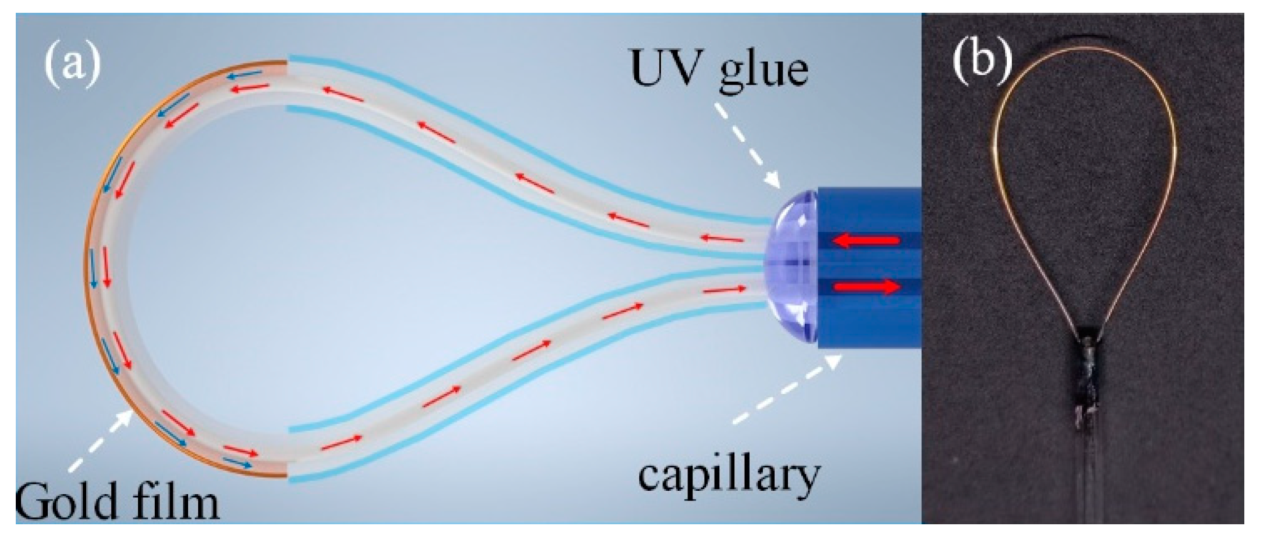
2. Fabrication and Sensing Principle
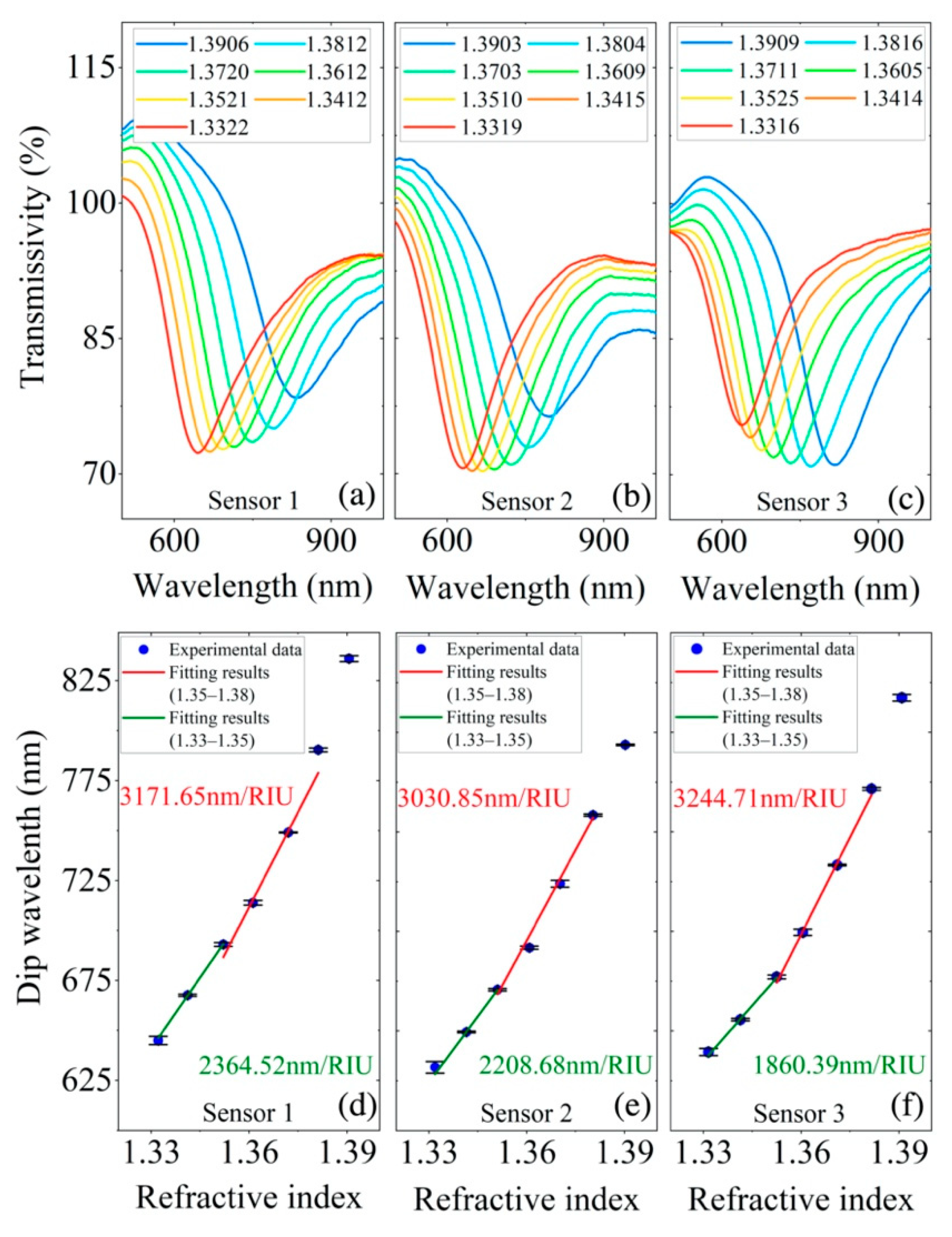
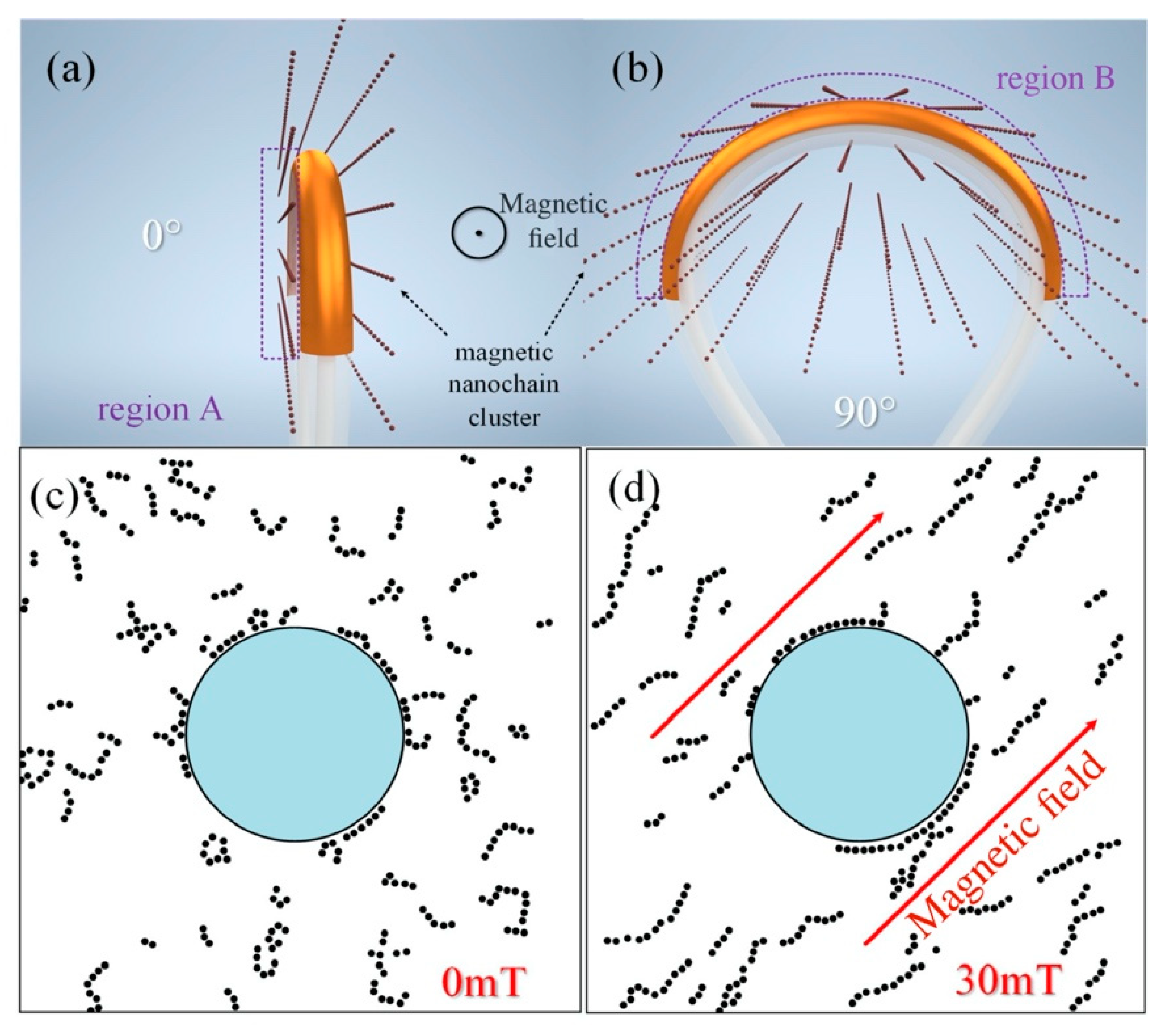
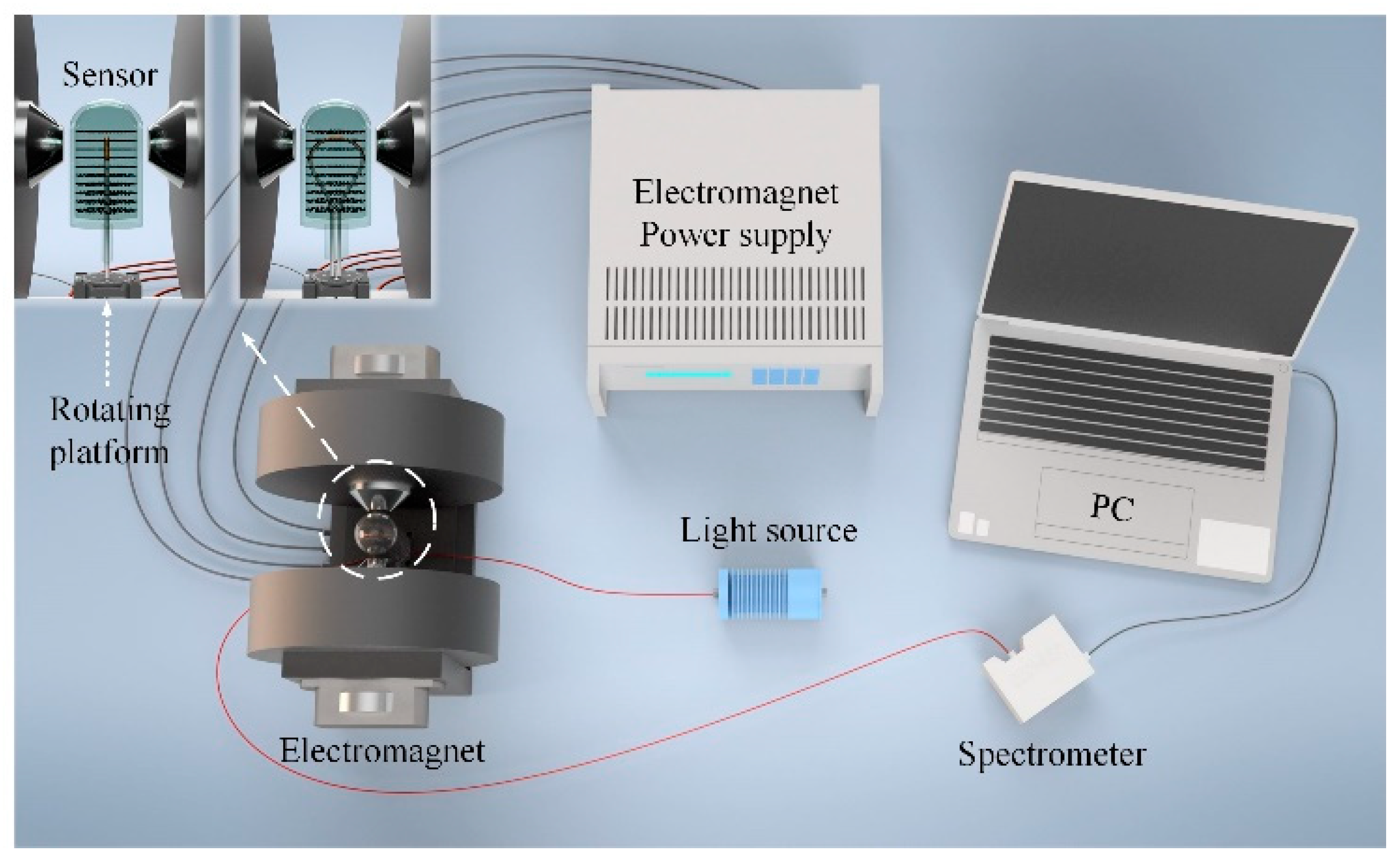
3. Experimental Details and Discussion
4. Conclusions
Author Contributions
Funding
Data Availability Statement
Conflicts of Interest
References
- Zu, P.; Chan, C.C.; Lew, W.S.; Jin, Y.; Zhang, Y.; Liew, H.F.; Chen, L.H.; Wong, W.C.; Dong, X. Magneto-optical fiber sensor based on magnetic fluid. Opt. Lett. 2012, 37, 398–400. [Google Scholar] [CrossRef] [PubMed]
- Zhao, Y.; Lv, R.; Li, H.; Wang, Q. Simulation and experimental measurement of magnetic fluid transmission characteristics subjected to the magnetic field. IEEE Trans. Magn. 2014, 50, 4600107. [Google Scholar] [CrossRef]
- Zhao, Y.; Lv, R.; Zhang, Y.; Wang, Q. Novel optical devices based on the transmission properties of magnetic fluid and their characteristics. Opt. Laser. Vol. 2012, 50, 1177–1184. [Google Scholar] [CrossRef]
- Zhang, C.; Pu, S.; Hao, Z.; Wang, B.; Yuan, M.; Zhang, Y. Magnetic field sensing based on whispering gallery mode with nanostructured magnetic fluid-infiltrated photonic crystal fiber. Nanomaterials 2022, 12, 862. [Google Scholar] [CrossRef]
- Zhang, Y.; Pu, S.; Li, Y.; Hao, Z.; Li, D.; Yan, S.; Yuan, M.; Zhang, C. Magnetic field and temperature dual-parameter sensor based on nonadiabatic tapered microfiber cascaded with FBG. IEEE Access 2022, 10, 15478–15486. [Google Scholar] [CrossRef]
- Deng, M.; Huang, C.; Liu, D.; Jin, W.; Zhu, T. All fiber magnetic field sensor with ferrofluid-filled tapered microstructured optical fiber interferometer. Opt. Express 2015, 23, 20668–20674. [Google Scholar] [CrossRef]
- Dong, S.; Pu, S.; Wang, H. Magnetic field sensing based on magnetic-fluid-clad fiber-optic structure with taper-like and lateral-offset fusion splicing. Opt. Express 2014, 22, 19108–19116. [Google Scholar] [CrossRef]
- Luo, L.; Pu, S.; Tang, J.; Zeng, X.; Lahoubi, M. Reflective all-fiber magnetic field sensor based on microfiber and magnetic fluid. Opt Express 2015, 23, 18133–18142. [Google Scholar] [CrossRef]
- Xia, J.; Wang, F.; Luo, H.; Wang, Q.; Xiong, S. A magnetic field sensor based on a magnetic fluid-filled FP-FBG structure. Sensors 2016, 16, 620. [Google Scholar] [CrossRef] [Green Version]
- Zhao, Y.; Lv, R.; Ying, Y.; Wang, Q. Hollow-core photonic crystal fiber Fabry–Perot sensor for magnetic field measurement based on magnetic fluid. Opt. Laser Technol. 2012, 44, 899–902. [Google Scholar] [CrossRef]
- Candiani, A.; Margulis, W.; Sterner, C.; Konstantaki, M.; Pissadakis, S. Phase-shifted Bragg microstructured optical fiber gratings utilizing infiltrated ferrofluids. Opt. Lett. 2011, 36, 2548–2550. [Google Scholar] [CrossRef] [PubMed]
- Candiani, A.; Konstantaki, M.; Margulis, W.; Pissadakis, S. A spectrally tunable microstructured optical fibre Bragg grating utilizing an infiltrated ferrofluid. Opt. Express 2010, 18, 24654–24660. [Google Scholar] [CrossRef] [PubMed]
- Liu, T.; Chen, Y.; Han, Q.; Lv, X. Magnetic field sensor based on U-bent single-mode fiber and magnetic fluid. IEEE Photonics J. 2014, 6, 5300307. [Google Scholar] [CrossRef]
- Fang, Y.L.; Huang, Y.H.; Kuo, C.Y.; Chiang, C.C. U-bend fiber optical sensor for magnetic field sensing. Opt. Quantum Electron. 2019, 51, 36. [Google Scholar] [CrossRef]
- Chen, Y.; Han, Q.; Liu, T.; Lan, X.; Xiao, H. Optical fiber magnetic field sensor based on single-mode-multimode-single-mode structure and magnetic fluid. Opt. Lett. 2013, 38, 3999–4001. [Google Scholar] [CrossRef]
- Wang, H.; Pu, S.; Wang, N.; Dong, S.; Huang, J. Magnetic field sensing based on singlemode-multimode-singlemode fiber structures using magnetic fluids as cladding. Opt. Lett. 2013, 39, 3765–3768. [Google Scholar] [CrossRef]
- Mao, L.; Pu, S.; Su, D.; Wang, Z.; Zeng, X.; Lahoubi, M. Magnetic field sensor based on cascaded microfiber coupler with magnetic fluid. J. Appl. Phys. 2016, 120, 093102. [Google Scholar] [CrossRef]
- Yuan, M.; Pu, S.; Li, D.; Li, Y.; Hao, Z.; Zhang, Y.; Zhang, C.; Yan, S. Extremely high sensitivity magnetic field sensing based on birefringence-induced dispersion turning point characteristics of microfiber coupler. Results Phys. 2021, 29, 104743. [Google Scholar] [CrossRef]
- Zu, P.; Chan, C.C.; Siang, L.W.; Jin, Y.; Zhang, Y.; Fen, L.H.; Chen, L.; Dong, X. Magneto-optic fiber Sagnac modulator based on magnetic fluids. Opt. Lett. 2011, 36, 1425–1427. [Google Scholar] [CrossRef]
- Lin, Q.; Xiao, Y.; Hu, Y.; Yan, F.; Hu, S.; Chen, Y.; Liu, G.; Chen, Y.; Luo, Y.; Chen, Z. Half-side gold-coated hetero-core fiber for highly sensitive measurement of a vector magnetic field. Opt. Lett. 2020, 45, 4746–4749. [Google Scholar] [CrossRef]
- Yin, J.; Yan, P.; Chen, H.; Yu, L.; Jiang, J.; Zhang, M.; Ruan, S. All-fiber-optic vector magnetometer based on anisotropic magnetism-manipulation of ferromagnetism nanoparticles. Appl. Phys. Lett. 2017, 110, 5187. [Google Scholar] [CrossRef]
- Candiani, A.; Konstantaki, M.; Margulis, W.; Pissadakis, S. Optofluidic magnetometer developed in a microstructured optical fiber. Opt. Lett. 2012, 37, 4467–4469. [Google Scholar] [CrossRef] [PubMed]
- Zhang, X.; Peng, W. Bent fiber interferometer. J. Lightwave Technol. 2015, 33, 3351–3356. [Google Scholar] [CrossRef]
- Chiang, C.C.; Chao, J.C. Whispering gallery mode based optical fiber sensor for measuring concentration of salt solution. J. Nanomater. 2013, 2013, 1–4. [Google Scholar] [CrossRef] [Green Version]
- Nam, S.H.; Yin, S. High-temperature sensing using whispering gallery mode resonance in bent optical fibers. IEEE Photonics Technol. Lett. 2005, 17, 2391–2393. [Google Scholar] [CrossRef]
- He, J.; Liao, C.; Yang, K.; Liu, S.; Yin, G.; Sun, B.; Zhou, J.; Zhao, J.; Wang, Y. High-sensitivity temperature sensor based on a coated single-mode fiber loop. J. Lightwave Technol. 2015, 33, 4019–4026. [Google Scholar] [CrossRef]
- Homola, J. Surface Plasmon Resonance Based Sensors; Springer: Berlin/Heidelberg, Germany, 2006. [Google Scholar]
- McDonagh, C.; Burke, C.S.; MacCraith, B.D. Optical chemical sensors. Chem. Rev. 2015, 108, 400–422. [Google Scholar] [CrossRef]
- Homola, J. On the sensitivity of surface plasmon resonance sensors with spectral interrogation. Sens. Actuators B 1997, 41, 207–211. [Google Scholar] [CrossRef]
- Slavík, R.; Homola, J.; Ctyroký, J. Single-mode optical fiber surface plasmon resonance sensor. Sens. Actuators B 1999, 54, 74–79. [Google Scholar] [CrossRef]
- Liu, T.; Chen, Y.; Han, Q.; Liu, F.; Yao, Y. Sensor based on macrobent fiber Bragg grating structure for simultaneous measurement of refractive index and temperature. Appl. Opt. 2016, 55, 791–795. [Google Scholar] [CrossRef]
- Chen, L.; Zhang, W.; Wang, L.; Zhou, Q.; Sieg, J.; Zhao, D.; Wang, B.; Yan, T.; Wang, S. Fiber refractive index sensor based on dual polarized Mach-Zehnder interference caused by a single-mode fiber loop. Appl. Opt. 2016, 55, 63–69. [Google Scholar] [CrossRef]
- Li, Y.; Pu, S.; Hao, Z.; Yan, S.; Zhang, Y.; Lahoubi, M. Vector magnetic field sensor based on U-bent single-mode fiber and magnetic fluid. Opt. Express 2021, 29, 5236–5246. [Google Scholar] [CrossRef] [PubMed]
- Dyshlyuk, A.V.; Vitrik, O.B.; Kulchin, Y.N.; Mitsai, E.V.; Cherepakhin, A.B.; Branger, C.; Brisset, H.; Iordache, T.V.; Sarbu, A. Numerical and experimental investigation of surface plasmon resonance excitation using whispering gallery modes in bent metal-clad single-mode optical fiber. J. Lightwave Technol. 2017, 35, 5425–5431. [Google Scholar] [CrossRef]
- Zhang, Y.; Liang, P.; Wang, Y.; Liu, Z.; Wei, Y.; Zhu, Z.; Zhao, E.; Yang, J.; Yuan, L. Cascaded distributed multichannel fiber SPR sensor based on gold film thickness adjustment approach. Sens. Actuators A 2017, 267, 526–531. [Google Scholar] [CrossRef]
- Haddouche, I.; Cherbi, L.; Ferhat, M.L. Analytical modelization of a fiber optic-based surface plasmon resonance sensor. Opt. Commun. 2017, 402, 618–623. [Google Scholar] [CrossRef]
- Zhang, Z.; Guo, T.; Zhang, X.; Xu, J.; Xie, W.; Nie, M.; Wu, Q.; Guan, B.; Albert, J. Plasmonic fiber-optic vector magnetometer. Appl. Phys. Lett. 2016, 108, 101105. [Google Scholar] [CrossRef]
- Lv, R.; Zhao, Y.; Li, H.; Hu, H.F. Theoretical analysis and experimental measurement of birefringence properties in magnetic fluid subjected to magnetic field. IEEE Trans. Magn. 2015, 51, 1–5. [Google Scholar] [CrossRef]
- Nabighian, M.N.; Grauch, V.; Hansen, R.O.; Lafehr, T.R.; Pearson, W.C.; Phillips, J.D. The historical development of the magnetic method in exploration. Geophysics 2005, 70, 33–61. [Google Scholar] [CrossRef]
- Savukov, I.; Karaulanov, T. Magnetic-resonance imaging of the human brain with an atomic magnetometer. Appl. Phys. Lett. 2013, 103, 115–120. [Google Scholar] [CrossRef] [Green Version]
- Pu, S.; Chen, X.; Chen, Y.; Liao, W.; Chen, L.; Xia, Y. Measurement of the refractive index of a magnetic fluid by the retroreflection on the fiber-optic end face. Appl. Phys. Lett. 2015, 86, 611. [Google Scholar] [CrossRef]
- Lu, T.; Sun, Y.; Moreno, Y.; Yan, Z.; Wang, C.; Sun, Q.; Wan, H.; Liu, D.; Zhang, L. Vector magnetic field sensor based on excessively tilted fiber grating assistant with magnetic fluids. In Proceedings of the 2018 Asia Communications and Photonics Conference, Hangzhou, China, 26–29 October 2018. [Google Scholar]
- Cui, J.; Qi, D.; Tian, H.; Li, H. Vector optical fiber magnetometer based on capillaries filled with magnetic fluid. Appl. Opt. 2019, 58, 2754. [Google Scholar] [CrossRef] [PubMed]
- Li, Y.; Pu, S.; Zhao, Y.; Zhang, R.; Jia, Z.; Yao, J.; Hao, Z.; Han, Z.; Li, D.; Li, X. All-fiber-optic vector magnetic field sensor based on side-polished fiber and magnetic fluid. Opt. Express 2019, 27, 35182–35188. [Google Scholar] [CrossRef] [PubMed]
- Zhang, J.; Jiang, Y.; Zhang, X.; Chen, H.; Guo, Z.; Wang, W. Magnetic field vector sensor based on a cascaded structure of core-offset Fabry–Perot interferometer and a magnetic fluid infiltrated glass capillary. J. Opt. Soc. Am. B 2021, 38, 102902–102906. [Google Scholar] [CrossRef]
- Jiang, Z.; Dong, J.; Hu, S.; Zhang, Y.; Chen, Y.; Luo, Y.; Zhu, W.; Qiu, W.; Lu, H.; Guan, H.; et al. High-sensitivity vector magnetic field sensor based on side-polished fiber plasmon and ferrofluid. Opt. Lett. 2018, 43, 4743–4746. [Google Scholar] [CrossRef] [PubMed]
- Hao, Z.; Pu, S.; Wang, J.; Liu, W.; Zhang, C.; Fan, Y.; Lahoubi, M. Dual-channel temperature-compensated vector magnetic field sensor based on lab-on-a-fiber-tip. Opt. Express 2022, 30, 25208–25218. [Google Scholar] [CrossRef] [PubMed]


| Sensing Structure | Fabrication Method | Detecting Range | Maximum Sensitivity | Reference |
|---|---|---|---|---|
| STS + lateral-offset | Offset splicing | 0–16 mT | 222.0 pm/mT | [21] |
| Tilted fiber grating | UV inscribed | 0–15 mT | 260 pm/mT | [42] |
| SMF fused with capillary | Tapered | 0–110 mT | 112 pm/mT | [43] |
| SPF-SNS | Side-polished | 0–30 mT | 2370 pm/mT | [44] |
| TFBG + gold film | Gold plating | 0–18 mT | 1800 pm/mT | [37] |
| FP + lateral-offset | Offset splicing | 0–9 mT | 4.63 pm/mT | [45] |
| D-shape fiber + gold film | Side polished + gold plating | 0–23 mT | 598.7 pm/Oe (5987 pm/mT) | [46] |
| Wedge-shape + gold film | Tip polished + gold plating | 0–22 mT | 1100 pm/mT | [47] |
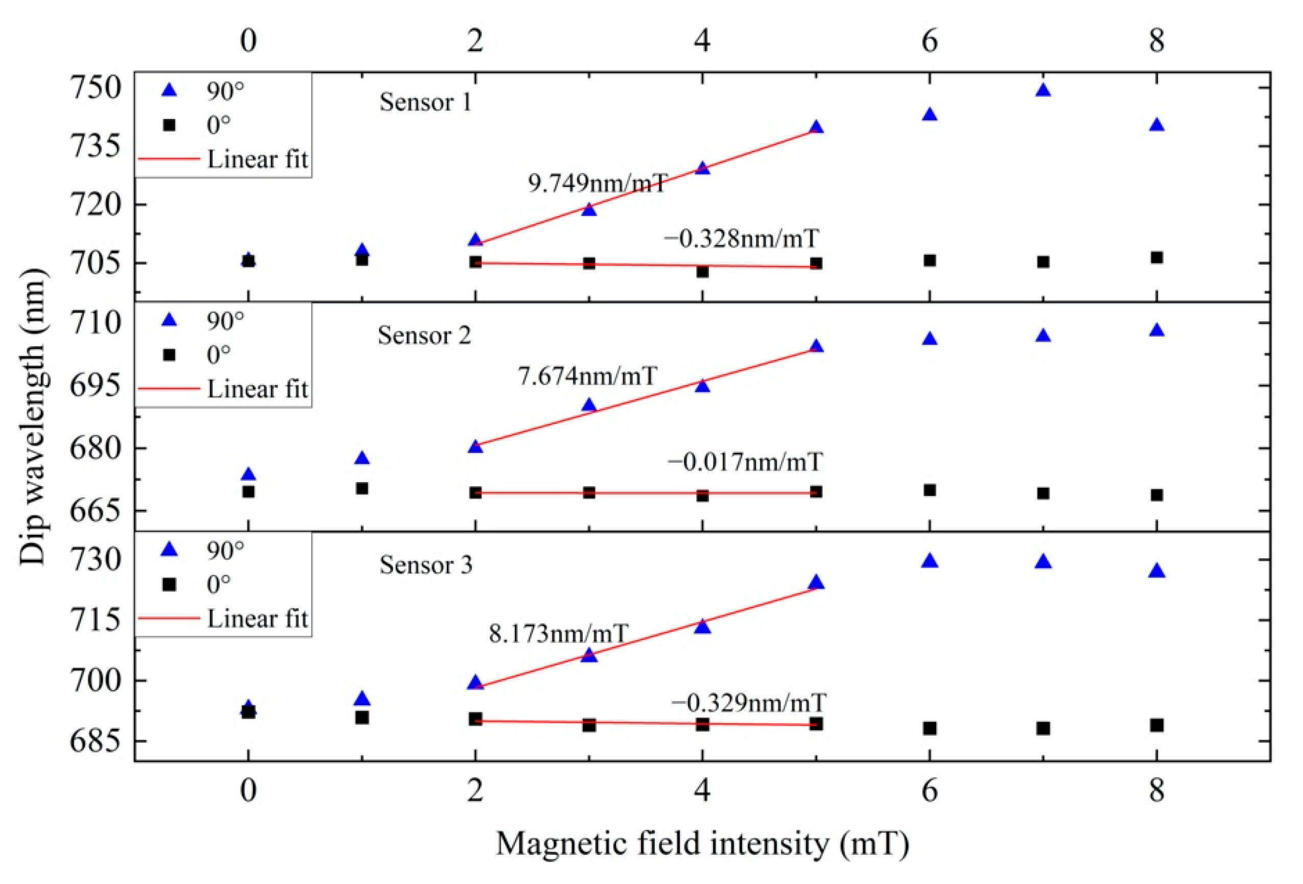
| Bent MMF + gold film | Bent + gold plating | 0–8 mT | 9749 pm/mT | This work |
Publisher’s Note: MDPI stays neutral with regard to jurisdictional claims in published maps and institutional affiliations. |
© 2022 by the authors. Licensee MDPI, Basel, Switzerland. This article is an open access article distributed under the terms and conditions of the Creative Commons Attribution (CC BY) license (https://creativecommons.org/licenses/by/4.0/).
Share and Cite
Liu, W.; Pu, S.; Hao, Z.; Wang, J.; Fan, Y.; Zhang, C.; Wang, J. Fiber-Optic Vector-Magnetic-Field Sensor Based on Gold-Clad Bent Multimode Fiber and Magnetic Fluid Materials. Materials 2022, 15, 7208. https://doi.org/10.3390/ma15207208
Liu W, Pu S, Hao Z, Wang J, Fan Y, Zhang C, Wang J. Fiber-Optic Vector-Magnetic-Field Sensor Based on Gold-Clad Bent Multimode Fiber and Magnetic Fluid Materials. Materials. 2022; 15(20):7208. https://doi.org/10.3390/ma15207208
Chicago/Turabian StyleLiu, Weinan, Shengli Pu, Zijian Hao, Jia Wang, Yuanyuan Fan, Chencheng Zhang, and Jingyue Wang. 2022. "Fiber-Optic Vector-Magnetic-Field Sensor Based on Gold-Clad Bent Multimode Fiber and Magnetic Fluid Materials" Materials 15, no. 20: 7208. https://doi.org/10.3390/ma15207208
APA StyleLiu, W., Pu, S., Hao, Z., Wang, J., Fan, Y., Zhang, C., & Wang, J. (2022). Fiber-Optic Vector-Magnetic-Field Sensor Based on Gold-Clad Bent Multimode Fiber and Magnetic Fluid Materials. Materials, 15(20), 7208. https://doi.org/10.3390/ma15207208