1. Introduction
A sandwich structure is made up of two basic components: a thinner external layer (facesheet), made of a stiffer material with better resistance properties, and a thicker but light internal layer (core), made of a different material. When joined together, the layers form a light, stiff, and durable structure which is stronger than similar monolithic structures [
1,
2,
3]. Along with laminates, sandwich structures are classified as layered composites. Depending on their intended use, they can be made of different materials and can have different geometries and methods of stiffening and layer bonding. Sandwich structures can be divided into fully metal, hybrid, and composite structures, depending on the type of materials that make them up. Cavity milling is more difficult with hybrid layered composites than in the case of metal structures due to the heterogeneity and anisotropy of the structures resulting from materials with different mechanical and physical properties being bound together. In addition, bonding such materials requires considerable effort [
4]. Moreover, sandwich structures are believed to be difficult to machine. During the machining of a sandwich structure composed of aluminum alloy and a carbon-fiber reinforced polymer (CFRP), it is additionally necessary to overcome difficulties related to the deformation of the upper and lower layers of the material, the interference of metal chips with the composite and the possible accumulation of aluminum shavings or carbon dust between the facings of the sandwich structure if it delaminates [
5]. The heavy-duty carbon fibers used in composites are difficult to break and tend to drag, which very often causes them to develop micro-cracks and to delaminate along the operating direction of the tool [
6]. Milling of CFRP composite requires frequent replacement of the milling tool, as the abrasive properties of carbon fiber cause premature wear. Furthermore, when machining CFRP composites, the milling tool alternately cuts hard fibers and the softer material of the skin, also accelerating the wear of the milling cutter [
7,
8].
Although hybrid layered structures are frequently used in many industries, the optimal conditions for machining this type of materials have not yet been adequately determined. Most studies focus on the damage to sandwich structures and their properties [
2], compare their properties with those of similar monolithic structures [
9], or review current trends in the use of such materials [
10,
11]. Additionally, recommendations on the machining of hybrid layered materials are based primarily on studies of CFRP composite processing.
Surface roughness is one of the most important and most commonly used properties that characterize the quality of a milled surface. It affects dimensional accuracy, alignment and the correct operation of machine and device parts [
3,
12,
13]. Layered materials have been widely used in aerospace as structural components and parts of aircraft equipment. Components used in the aerospace industry must meet strict quality criteria due to its narrow tolerance ranges. Protective and decorative coatings are often applied to aviation components. High values of surface roughness parameters may result in insufficient adhesion of the coating and thus reduce its durability [
14]. The heterogeneity and anisotropy of the machined material are also extremely important properties. The different surface roughness on the sandwich structure layers can significantly reduce the visual effect of the components. Therefore, it is important to obtain a uniform surface of the sandwich structure with the desired roughness and surface topography. Surface roughness is affected by multiple parameters, such as the level of wear of the cutting tool, the levels of vibration, the stability of the machining process, and the cutting parameters [
15,
16,
17].
Many researchers have analyzed the roughness and geometric structure of a fiber composite surface after machining. However, no studies have been carried out to examine the roughness of milled hybrid sandwich structures. Some have noted [
18,
19] that milling strength and surface roughness during the machining of CFRP composites depend on the milling parameters, with feed rate being the main factor that affects the quality of the surface after machining. Suresh et al. [
20] made similar conclusions. Ramulu et al. [
21] conducted research on the machinability of CFRP composites. They noted that a higher cutting speed results in less surface roughness, which is supported by results published by Çolak et al. [
22]. Channdrasekaran and Devarasiddappa [
23] noted that the surface roughness of machined fiber composites is linearly dependent on the feed rate and inversely dependent on the cutting speed. Bayraktar et al. [
24] determined the impact of the cutting tool (material, geometry, and tool coating) and the process parameters (cutting speed and feed rate) on the cutting speed and surface roughness of CFRP composites after milling. It was noted that feed rate had the greatest impact on the quality of the machined surface among the examined factors. A non-coated cutter produced the lowest cutting strength and surface roughness values, which increased with the number of flutes and the angle of inclination of the cutter’s cutting edge. Ramirez et al. [
25] examined cutter wear and surface roughness after drilling CFRP composite. They concluded that new criteria must be formulated to assess surface topography after machining due to the anisotropy and heterogeneity of the machined material. Zarrouk et al. [
26] examined the impact of machining conditions (rotational speed and machining depth) on the machining strength and surface quality of a milled nomex honeycomb. The results of the experiment were compared to a theoretical model. Eskandari et al. [
27] studied the cutting speed, feed rate, and drill bit diameter in terms of their impact on the quality of openings drilled into sandwich structures with a foam core. Grilo et al. [
28] investigated the delamination of drilled CFRP composites associated with drill bit diameter and machining parameters (feed rate and rotational speed). They showed that the feed rate was related directly by a proportional relationship to the delamination factor and the adjusted delamination factor. Shunmugesh et al. [
29] used Grey Relational Analysis and the Taguchi technique to optimize machining conditions (machining speed, feed rate and drill bit diameter) in the context of delamination and surface quality (surface roughness and the dimensional accuracy of openings) after CFRP composite drilling. Khoran et al. [
30] also studied the impact of machining parameters on the quality of openings produced by drilling. The experiment was performed on sandwich structures made of various materials (balsa wood, foamed materials) and used digital technology to measure the delamination and uncut fiber coefficients. Xu et al. [
31] studied the effects of cutting parameters and tool geometry on surface roughness and cutting forces after milling of CFRP composites with a diamond tool (PCD). They showed that a higher value of tool rake angel did not affect surface roughness but resulted in lower cutting forces. Oláh et al. [
32] reviewed solutions used in the cavity milling of sandwich structures and discussed the results of a simulation for cutting a honeycomb structure using a dedicated tool. The use of numerical methods such as the finite element method (FEM), the boundary element method (BEM), mathematical modeling, and the application of machine learning methods can help reduce the time and cost of testing, which is extremely important when testing relatively expensive composite materials [
33,
34]. Onyibo and Safaei [
35] used the finite element method (FEM) to design sandwich structures with a honeycomb core. The study compared the mechanical properties obtained by modeling structures with different core thicknesses and made of different materials. Lavaggi et al. [
36] studied the bonding of a honeycomb core with facesheets made of thermoset materials. They used three TGLM (Theory guided machine learning) models to optimize bonding properties such as the level of facesheets consolidation and bond-line porosity.
Milling an Al/CFRP structure causes heavy wear on the cutting tools, resulting in a poorer-quality machined surface. One way to obtain high-quality surfaces after milling is to use coated tools. Wang et al. [
37] studied the tool wear during the drilling of CFRP/Ti structures. The wear of the cutter after machining a sandwich structure was compared against reference samples (used to machine separate composite and metal layers). The results indicated that the wear of the tool on the side of the metal layer was nine times lower than that on the side of the composite. The tests also found that each type of material resulted in a different type of wear. Hosokawa et al. [
38] presented the results of CFRP composites milling using diamond-coated tools with a variable inclination angle of the cutting edge. They were able to demonstrate that the occurrence of defects on the surface of the machined material depended on machining forces, whereas tool wear depended on the orientation of the fibers.
The complexity of layered composites can cause many difficulties during the machining process. There are no comprehensive studies on the surface quality of sandwich structures after milling. There are also no standards or recommendations indicating an acceptable value or level of defect uniformity after milling of this type of constructions. Recommendations for cutting conditions (for example, recommended tool geometry, cutting parameters, machining configuration) have also not been developed. It causes machining conditions for this type of materials to be currently chosen based on recommendations for the composite layer, and cutting tools are dedicated for use with specific core types. This approach leads to a non-uniform surface quality of the sandwich structure, and this affects its further operation and aesthetic qualities. This study investigates the effect of the machining configuration (arrangement of layers forming the sandwich structure) and the type of tool (presence of a TiAlN coating) on the surface quality of the Al/CFRP sandwich structure after milling. The surface quality was defined by surface roughness and surface topography. A new and innovative approach is to evaluate the surface quality of the tested structure on the basis of the uniformity of defect distribution on the surface of individual layers of the structure. In addition, the IR coefficient has been proposed as a tool for assessing the surface uniformity of such materials. The obtained research results are targeted for use in industrial practice. Prior to the study, it was assumed that circumferential milling of a two-layer metal–polymer composite sandwich structure results in differences in surface quality of the layers making up the sandwich structure. Based on the results obtained, the research hypothesis was verified, and the influence of the studied variables on the research object was determined.
2. Materials and Methods
Tests were performed on a two-layer sandwich structure made up of an EN AW-2024 T3 aluminum alloy (Al) and a carbon-fiber-reinforced polymer (CFRP) with an alternating arrangement of fibers. In the experiment, the cutting speed vc [m/min], feed rate fz [mm/blade], axial milling depth ap [mm], radial milling depth ae [mm], materials forming the structure, shape, and dimensions of the samples were used as constant factors. The output factors were surface roughness, surface topography, and surface uniformity. A two-level total plan was used to plan the experiment. The influence of two independent variables was studied: machining configuration and tool type. The design of the considered sandwich structure limited the machining configuration to the occurrence of two states. In order to limit the research time, two states were also adopted for the second independent variable (tool type). The applied method of planning the experiment made it possible to quickly generate all possible combinations of states of the independent variables.
The used aluminum alloy is characterized by low density and increased yield strength [
39]. The alloy has low oxidation resistance, so it is not suitable for solutions where there is a risk of corrosion. The material is machinable but not suitable for anodizing and welding. One area of its application is the aerospace industry. The CFRP composite was created through a vacuum pressure impregnation process, using an autoclave manufactured by Scholz (Coesfeld, Germany). The proportion of carbon fibers in the hardened composite was around 60%.
Table 1 shows selected properties of the CFRP composite used in the test.
Scotch-Weld EC-9323 B/A (3M, Saint Paul, MN, USA) epoxy glue was used to bond the aluminum alloy and the CFRP composite. The polymerization process took place in a vacuum bag under a pressure of 0.1 MPa for a period of 24 h. The plates were then seasoned under ambient conditions for 14 days.
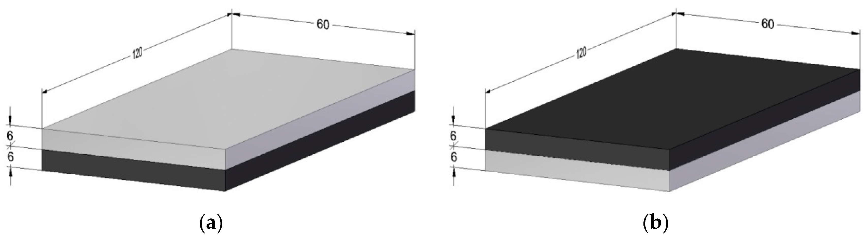
The machined samples had dimensions of 60
120
12 mm (
Figure 1). The thickness of a single layer was 6 mm. Due to low value of the adhesive layer (0.1 ± 0.02 mm), it was disregarded when determining the total thickness of the structure. The experiment analyzed the impact of two machining configurations:
Al/CFRP—milling starting from the metal layer (
Figure 1a)
CFRP/Al—milling starting from the composite layer (
Figure 1b)
Figure 1.
Tested sample: (a) Al/CFRP configuration, (b) CFRP/Al configuration (Unit: mm).
Figure 1.
Tested sample: (a) Al/CFRP configuration, (b) CFRP/Al configuration (Unit: mm).
Simultaneous circumferential milling using a VMC 800 HS machining centre (AVIA, Warsaw, Poland) was employed during the tests. The spindle performed right-hand rotation. The shorter edge of the sample (60 mm) was machined during the tests. Each sample was machined three times and the arithmetic mean of the three measurements was used in the analysis.
Figure 2 presents the scheme of the milling process.
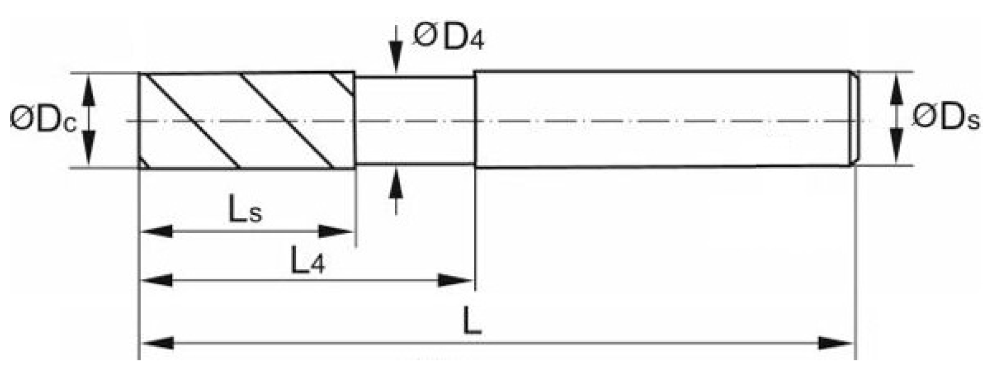
Manufacturers of machining tools currently tend to make dedicated tools for machining specific types of materials. This makes it particularly difficult to determine the tools and process parameters suitable for machining both the facesheet and core materials. Careful selection of the tool, its geometry and the technological parameters of the process is an important part of the experiment. The experiment used a Garant double-edged, solid carbide endmill by Hoffman Group (Munich, Germany). The shape and dimensions of the tool are presented in
Figure 3 and
Table 2.
To examine the impact of the tool coating on the quality of the surface after milling, an identical endmill was used, this one coated with a 5-μm thick TiAlN coating, applied using the PVD method. The tools and coating type were selected due to their versatility (suitability for machining aluminum alloys and plastics). The machining was carried out using constant milling parameters: a milling speed vc of 300 m/min, a feed rate fz of 0.08 mm/blade, an axial milling depth ap of 12 mm, and a radial milling depth ae of 4 mm. The parameters were chosen based on values recommended by the manufacturer of the tool for machining aluminum alloys and polymers. The value of ap was chosen so as to enable the simultaneous milling of both layers of the structure.
The roughness and topography of the surface were recorded using a 3D T8000 RC120-400 (Hommel-Etamic, Jena, Germany) surface roughness, waviness, and topography measurement device. The scheme of the experimental stand is shown in
Figure 4.
Ra (arithmetic mean deviation of the assessed profile), Rz (maximum height of the profile), and Rmax (maximum roughness depth) surface roughness parameters [
42], as well as the Sa (arithmetic mean height), Sz (maximum height), Sv (maximum pit height) and Sp (maximum peak height) surface topography parameters, were analyzed [
43]. Measurements were taken at a distance equal to half of the thickness of the sample from the sample’s edge so that the measured section was positioned centrally to the layer being examined. The roughness and topography of the surface were measured separately for each layer in the structure, longitudinally to the feed direction. The test involved taking 320 measurements on the surface of each layer. The total length of the measurement l
t, the length of the measurement section l
n and the length of the elementary section l
r were, respectively: l
t = 4.8 mm, l
n = 4.0 mm, l
r = 0.8 mm. The measuring interval was 15 µm. The measurement speed was 0.50 mm/s. The measurement time for one layer (320 measurement points) was about 2 h and 40 min.
The surface quality of the hybrid sandwich structures after milling may also be defined by the uniform or regularity of defect distribution on the machined surface. This is caused by the fact that the metal layer may have a different surface quality than the composite layer. Therefore, the surface uniformity was determined based on the roughness parameters of the surface, depending on the machining configuration and tool used (
Figure 5).
It was assumed that the most uniform surface was represented by the lowest difference between the values of a given surface roughness parameter of each layer (hmin), whereas the least uniform surface had the highest difference (hmax).
4. Discussion
The objective of this study was to determine the impact of machining configuration and tool type on the surface quality of the sandwich structure after milling. The results of the study indicate that similar values were obtained for the Rz and Rmax surface roughness parameters. The minimum and maximum values of the Ra surface roughness parameter were not obtained for the same cutting conditions, as was the case for the other parameters. This may have resulted from the fact that the Ra surface roughness parameter does not account for the presence of defects typical of fiber-reinforced polymers [
46].
Using the CFRP/Al machining configuration and a coated tool resulted in a higher value of Ra surface roughness parameter on the aluminum alloy and the CFRP surfaces. However, the statistical analysis indicated that the machining configuration was the only variable that had a statistically significant impact on the value of Ra surface roughness parameter obtained for the metal layer. The statistically significant variables for the composite layer were the machining configuration and the tool type. The interaction of these factors was statistically insignificant for both materials.
The results indicate that a composite material has a lower machinability—for all considered cutting conditions, lower values of the tested parameters were obtained for the surface of the metal layer. This was due to the heterogeneity and abrasive properties of the composite material and the presence of typical defects on its surface (including fiber pull-out and matrix cracking) [
47]. The values of Rz and Rmax surface roughness parameters were higher for the CFRP/Al configuration than the Al/CFRP configuration, for both the aluminum alloy and the CFRP composite [
48]. Obtaining higher values of the surface roughness parameters in the CFRP/Al configuration is due to the different properties of the materials forming the sandwich structure. The aluminum layer above the composite material stiffened the workpiece, making the machining more stable. Using a coated tool reduced the surface roughness of the aluminum alloy in the Al/CFRP configuration, while it increased the value in the CFRP/Al configuration. Using a coated tool with the composite layer resulted in higher values of Rz and Rmax surface roughness parameters in both configurations. This was the result of the thicker endmill material and the rounding of the milling edge caused by the tool coating [
49,
50]. The machining configuration had the most significant impact on the values of Rz and Rmax surface roughness parameter for the aluminum alloy, whereas the tool type was the major factor in the case of the CFRP composite. Different values of the tested surface roughness parameters for aluminum alloy and CFRP composite was also due to the anisotropy of the sandwich structure. The tool encountered different cutting resistances during machining—when cutting the CFRP composite, which has a lower density compared to aluminum alloy, a sudden change in cutting resistance occurred, and the tool was pulled deep into the workpiece. The result was the occurrence of a non-uniform quality on the surface of the sandwich structure.
The analysis of surface topography indicated that in most cases higher 3D surface roughness parameters were obtained for the composite layer. In addition, the topographies of the aluminum alloy and CFRP composite surfaces had different micro-irregularity arrangements.
The study went on to create a coefficient for assessing the surface uniformity of sandwich structures. Based on the values of the surface roughness parameters obtained through experimentation, differences in the quality of the layers that made up the sandwich structure were calculated for each variant. The results were compared against the calculated values of the newly-created coefficient IR, leading to the assumption that the minimal value of IR determines the most uniform quality of a sandwich structure. Analysis of the results showed that the cutting conditions (machining configuration and type of tool) allowing the lowest values of surface roughness parameters for the materials forming the structure did not guarantee the highest surface uniformity. This shows that surface uniformity is not the same as surface roughness and should still be considered separately. Therefore, it is necessary to continue research aimed at finding a tool and machining conditions to achieve surface roughness and surface uniformity at similar acceptable levels.


