
Effect of Sleeper-Ballast Particle Contact on Lateral Resistance of Concrete Sleepers in Ballasted Railway Tracks

Abstract
:1. Introduction
2. Material Specifications and DEM Simulations
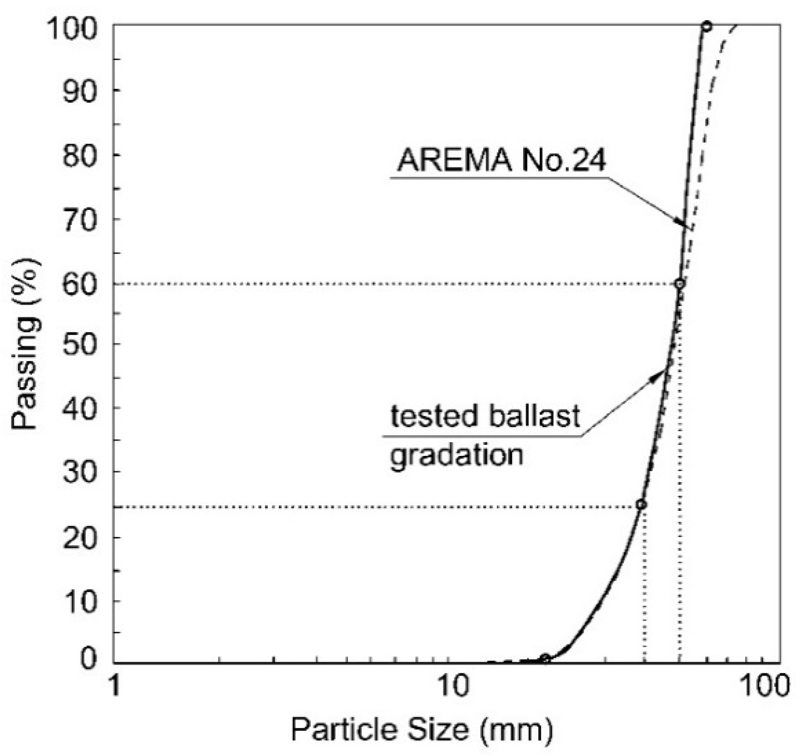
2.1. Ballast
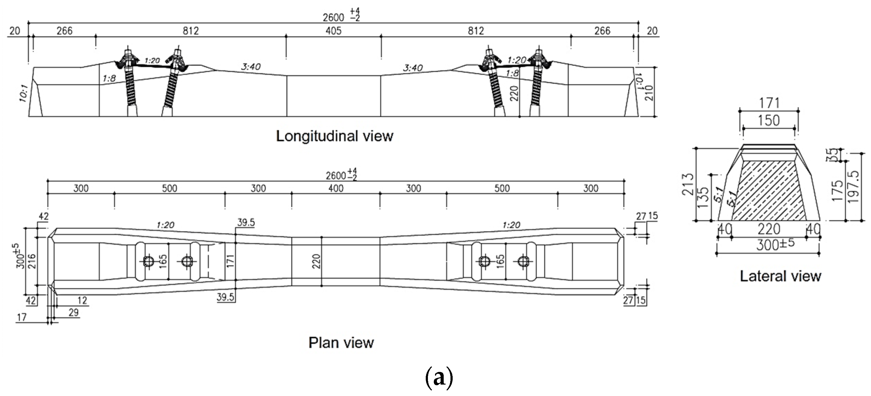
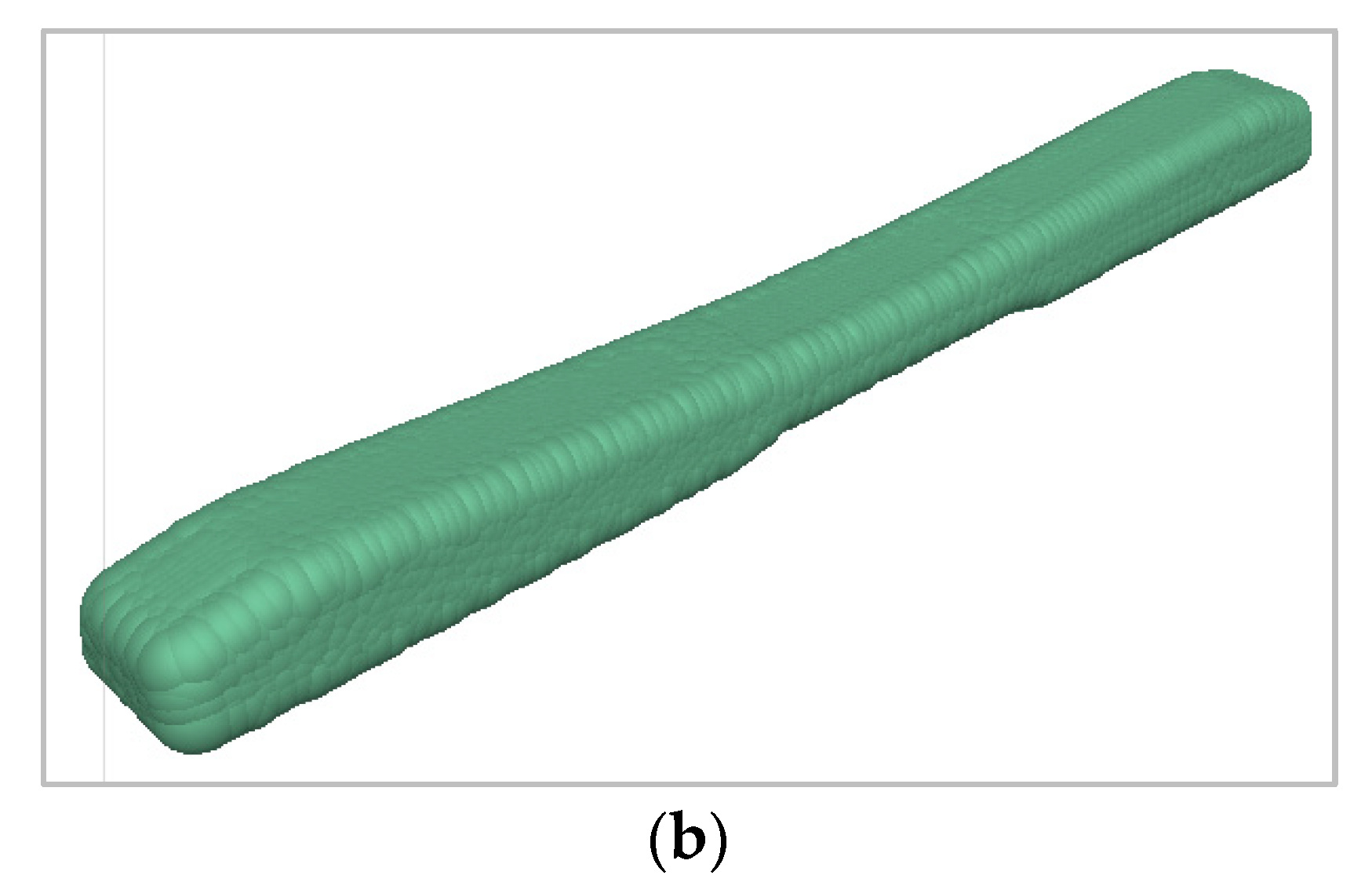
2.2. Sleeper
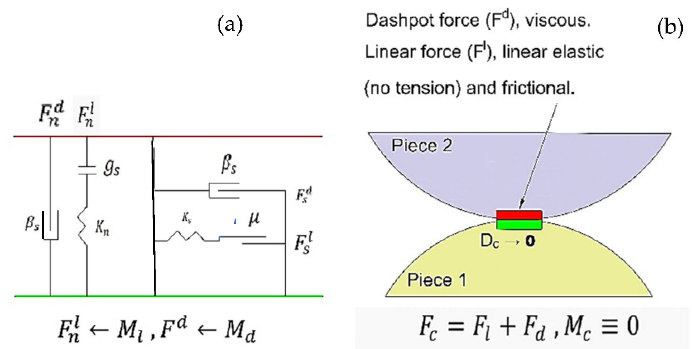
2.3. Contact Model
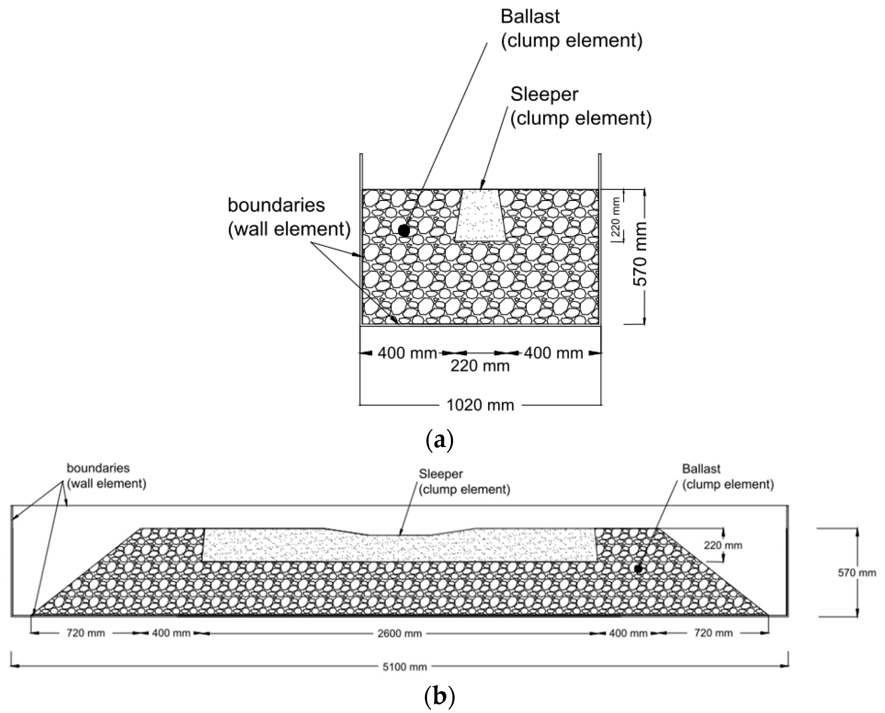
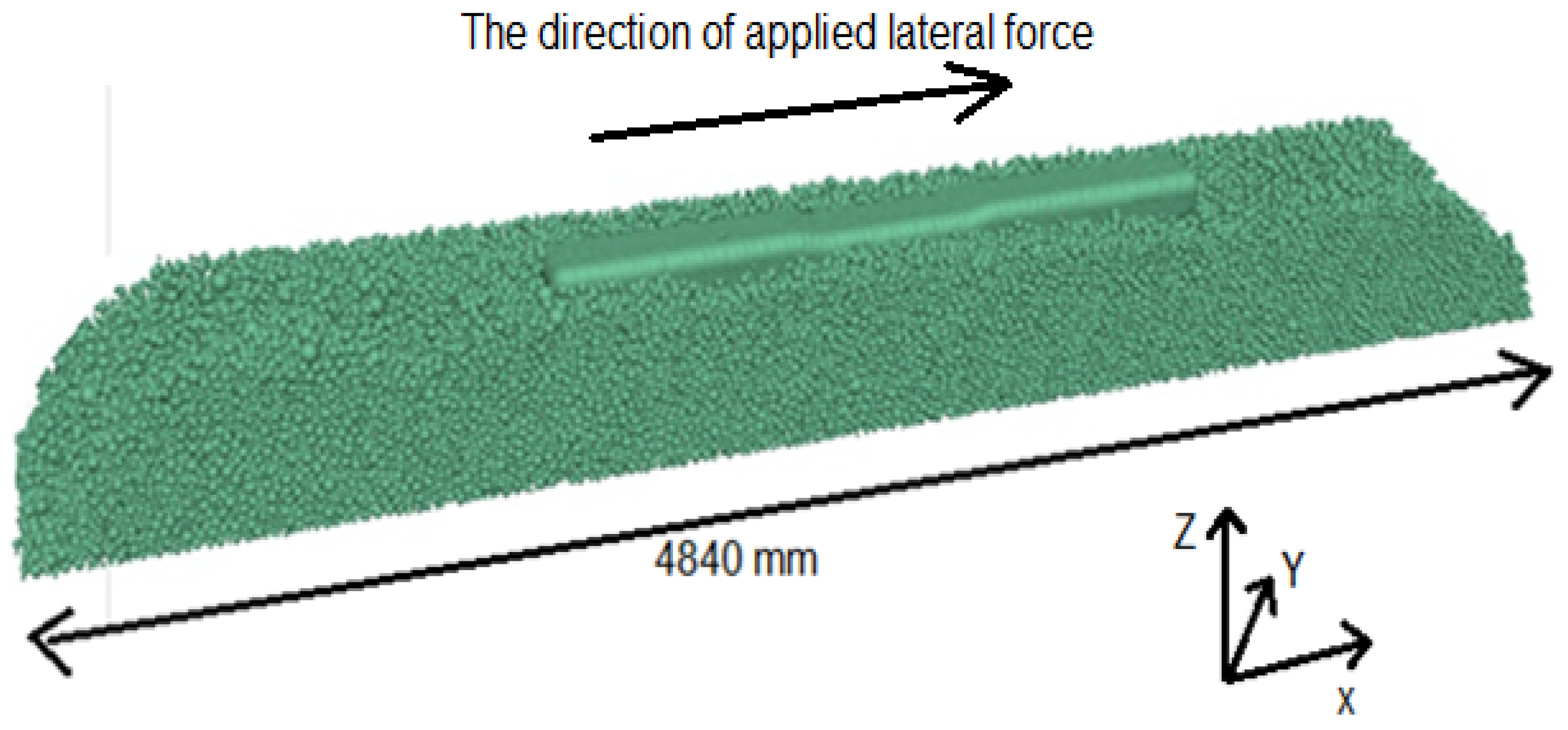
2.4. DEM Simulation
3. Results and Discussion
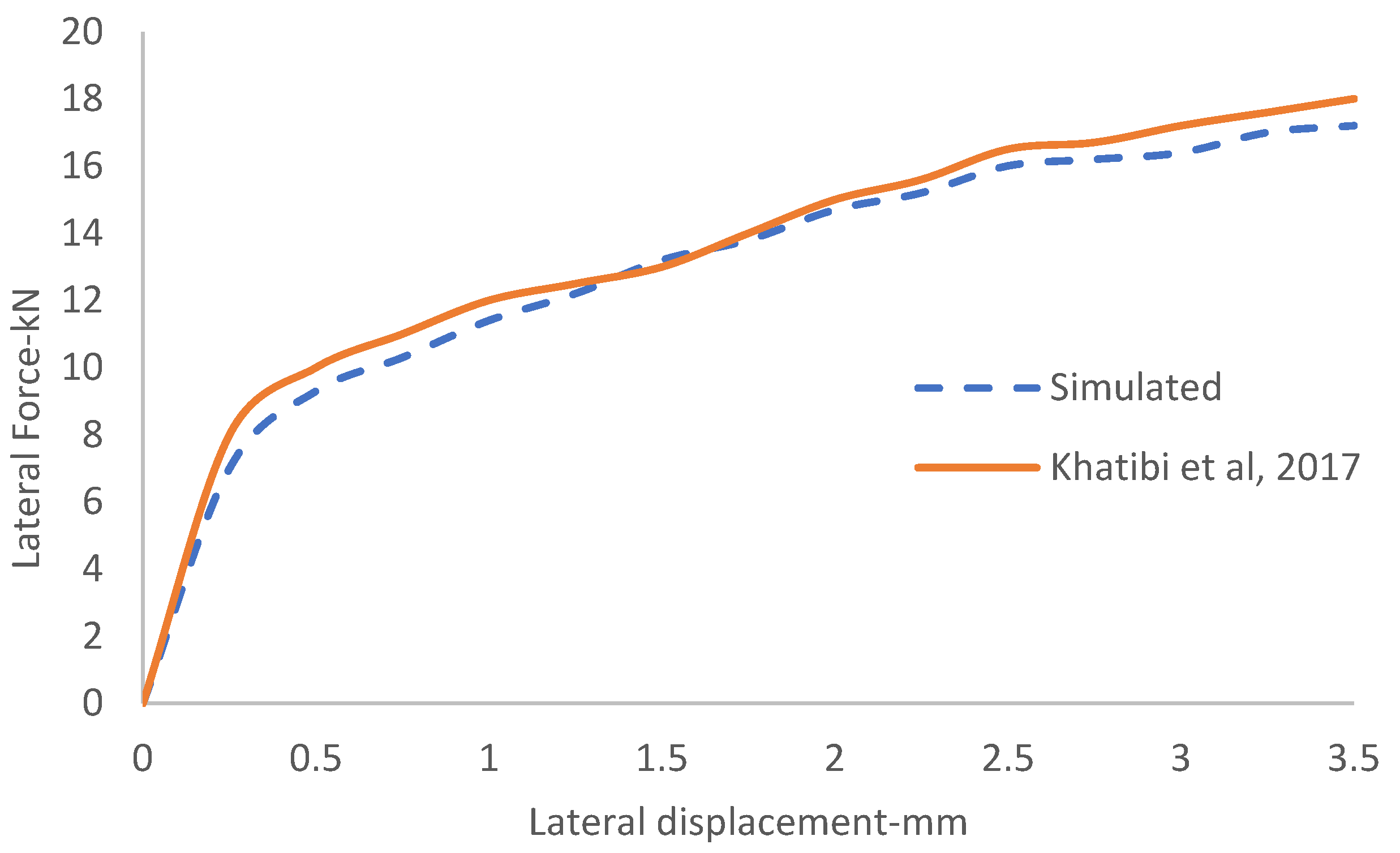
3.1. Validation
3.2. Parametric Study
3.3. Regression Equations
4. Conclusions
- The DEM results show a good agreement with experimental data in terms of lateral resistance displacement. However, there was a gap between the graph, which is naturally associated with dissimilarities of ballast and sleeper’s shapes and also the loading process and conditions;
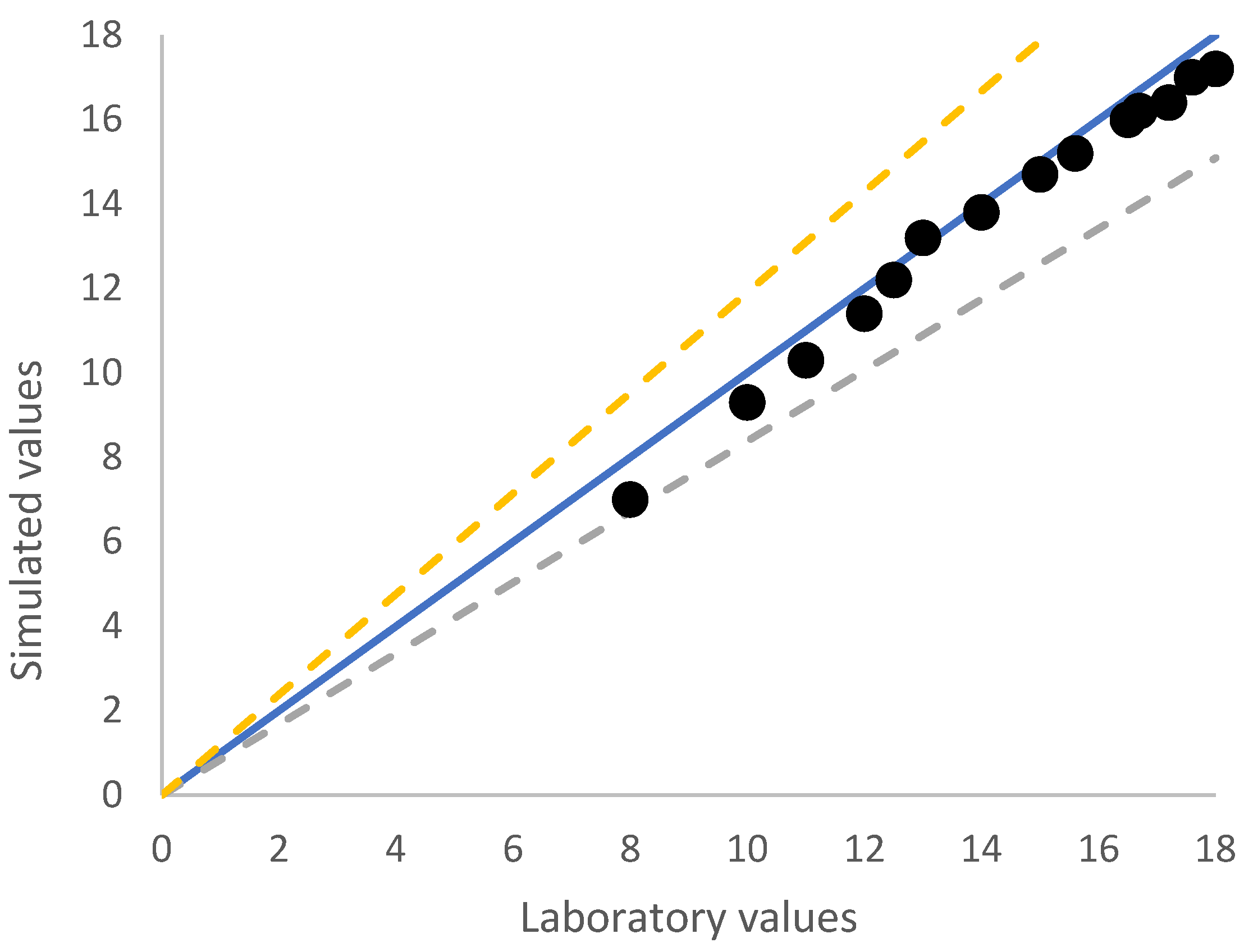
- A regression equation was obtained to predict the lateral resistance of a concrete sleeper as a function of three different surface areas of sleeper interacted with ballast aggregates. The accuracy of this equation was about 92%, which is reliable enough to be used in this regard;
- According to Table 2, the changing trend of Fmax from sleeper B-0 d to sleeper B-5 is decreasing, the area value of Af is increasing and Aa, Ab is decreasing. It shows that from B-0 to B-5, the downward trend of the Aa and Ab in the downward trend of fmax has more impact than Af. This is while the upward trend has started from B-6 and continues to B-16, which shows the greater influence of Af in this trend. In addition, equation 6 obtained from Table 2 shows the high influence of Af compared to Aa and Ab in Fmax. The effect value of Af in Fmax compared to Ab and Aa is 8.2 times and 14.5 times more, respectively;
- For recommending a sleeper, first of all, according to the standard gauge of the railway, which is 1433 mm [29], the suggested dimensions of the sleeper should be determined based on this gauge. As shown in Table 2, sleepers of B-0 to B-8 are 2889 mm to 1502 mm in length, respectively, and are suitable for supplying standard gauge. In addition, based on the results of maximum forces in Table 2, the sleeper of B-0 is recommended.
Author Contributions
Funding
Institutional Review Board Statement
Informed Consent Statement
Data Availability Statement
Conflicts of Interest
References
- Zhang, Z.; Xiao, H.; Wang, Y.; Fang, J.; Nadakatti, M.; Wang, H. Experimental study and discrete element analysis on lateral resistance of windblown sand railway. Transp. Geotech. 2022, 34, 100740. [Google Scholar] [CrossRef]
- Jing, G.; Aela, P.; Fu, H. The contribution of ballast layer components to the lateral resistance of ladder sleeper track. Constr. Build. Mater. 2019, 202, 796–805. [Google Scholar] [CrossRef]
- Fischer, S. Breakage Test of Railway Ballast Materials with New Laboratory Method. Period. Polytech. Civ. Eng. 2017, 61, 794–802. [Google Scholar] [CrossRef] [Green Version]
- Ngamkhanong, C.; Feng, B.; Tutumluer, E.; Hashash, Y.M.; Kaewunruen, S. Evaluation of lateral stability of railway tracks due to ballast degradation. Constr. Build. Mater. 2021, 278, 122342. [Google Scholar] [CrossRef]
- Jing, G.; Zhang, X.; Jia, W. Lateral resistance of polyurethane-reinforced ballast with the application of new bonding schemes: Laboratory tests and discrete element simulations. Constr. Build. Mater. 2019, 221, 627–636. [Google Scholar] [CrossRef]
- Sol-Sánchez, M.; Moreno-Navarro, F.; Tauste-Martínez, R.; Saiz, L.; Rubio-Gámez, M. Recycling Tire-Derived Aggregate as elastic particles under railway sleepers: Impact on track lateral resistance and durability. J. Clean. Prod. 2020, 277, 123322. [Google Scholar] [CrossRef]
- Esmaeili, M.; Zakeri, J.A.; Babaei, M. Laboratory and field investigation of the effect of geogrid-reinforced ballast on railway track lateral resistance. Geotext. Geomembr. 2017, 45, 23–33. [Google Scholar] [CrossRef]
- Koike, Y.; Nakamura, T.; Hayano, K.; Momoya, Y. Numerical method for evaluating the lateral resistance of sleepers in ballasted tracks. Soils Found. 2014, 54, 502–514. [Google Scholar] [CrossRef] [Green Version]
- Koyama, E.; Ito, K.; Hayano, K.; Momoya, Y. A new approach for evaluating lateral resistance of railway ballast associated with extended sleeper spacing. Soils Found. 2021, 61, 1565–1580. [Google Scholar] [CrossRef]
- Esmaeili, M.; Hosseini, S.; Sharavi, M. Experimental assessment of dynamic lateral resistance of railway concrete sleeper. Soil Dyn. Earthq. Eng. 2016, 82, 40–54. [Google Scholar] [CrossRef]
- Miri, A.; Zakeri, J.A.; Thambiratnam, D.; Chan, T. Effect of shape of concrete sleepers for mitigating of track buckling. Constr. Build. Mater. 2021, 294, 123568. [Google Scholar] [CrossRef]
- Esmaeili, M.; Khodaverdian, A.; Neyestanaki, H.K.; Nazari, S. Investigating the effect of nailed sleepers on increasing the lateral resistance of ballasted track. Comput. Geotech. 2016, 71, 1–11. [Google Scholar] [CrossRef]
- Liu, J.; Chen, R.; Liu, Z.; Liu, G.; Wang, P.; Wei, X. Comparative analysis of resistance characteristics of composite sleeper and concrete sleeper in ballast bed. Constr. Build. Mater. 2021, 300, 124017. [Google Scholar] [CrossRef]
- Jing, G.; Ji, Y.; Aela, P. Experimental and numerical analysis of anchor-reinforced sleepers lateral resistance on ballasted track. Constr. Build. Mater. 2020, 264, 120197. [Google Scholar] [CrossRef]
- Mansouri, P.; Zakeri, J.A.; Mohammadzadeh, S. Numerical and laboratory investigation on lateral resistance of ballasted track with HA110 sleeper. Constr. Build. Mater. 2021, 301, 124133. [Google Scholar] [CrossRef]
- Khatibi, F.; Esmaeili, M.; Mohammadzadeh, S. DEM analysis of railway track lateral resistance. Soils Found. 2017, 57, 587–602. [Google Scholar] [CrossRef]
- Guo, Y.; Fu, H.; Qian, Y.; Markine, V.; Jing, G. Effect of sleeper bottom texture on lateral resistance with discrete element modelling. Constr. Build. Mater. 2020, 250, 118770. [Google Scholar] [CrossRef]
- Jing, G.; Jia, W.; Wang, X.; Markine, V.; Nålsund, R.; Guo, Y. Experimental and numerical study on lateral resistance of frictional sleeper with arrowhead groove. Transp. Geotech. 2021, 30, 100638. [Google Scholar] [CrossRef]
- Jing, G.; Fu, H.; Aela, P. Lateral displacement of different types of steel sleepers on ballasted track. Constr. Build. Mater. 2018, 186, 1268–1275. [Google Scholar] [CrossRef]
- Mansouri, P.; Zakeri, J.-A.; Esmaeili, M.; Ghahremani, S. Discrete element method analysis of lateral resistance of different sleepers under different support conditions. Constr. Build. Mater. 2022, 327, 126915. [Google Scholar] [CrossRef]
- Itasca, M. Particle Flow Code in Three Dimensions (PFC3D); Itasca Consulting Group: Minneapolis, MN, USA, 2008. [Google Scholar]
- Zhu, X.; Qian, G.; Yu, H.; Yao, D.; Shi, C.; Zhang, C. Evaluation of coarse aggregate movement and contact unbalanced force during asphalt mixture compaction process based on discrete element method. Constr. Build. Mater. 2022, 328, 127004. [Google Scholar] [CrossRef]
- Li, J.; Zhang, J.; Zhang, A.; Peng, J. Evaluation on Deformation Behavior of Granular Base Material during Repeated Load Triaxial Testing by Discrete-Element Method. Int. J. Géoméch. 2022, 22, 04022210. [Google Scholar] [CrossRef]
- Lim, N.-H.; Kim, K.-J.; Bae, H.-U.; Kim, S. DEM Analysis of Track Ballast for Track Ballast–Wheel Interaction Simulation. Appl. Sci. 2020, 10, 2717. [Google Scholar] [CrossRef] [Green Version]
- Irazábal, J.; Salazar, F.; Oñate, E. Numerical modelling of granular materials with spherical discrete particles and the bounded rolling friction model. Application to railway ballast. Comput. Geotech. 2017, 85, 220–229. [Google Scholar] [CrossRef]
- Chen, C.; McDowell, G.; Thom, N. Discrete element modelling of cyclic loads of geogrid-reinforced ballast under confined and unconfined conditions. Geotext. Geomembr. 2012, 35, 76–86. [Google Scholar] [CrossRef]
- Taghavi, R. Automatic clump generation based on mid-surface in continuum and distinct element modeling in geome-chanics. In Proceedings of the 2nd International FLAC/DEM Symposium, Melbourne, Australia, 4–16 February 2011; pp. 791–797. [Google Scholar]
- Shahin, M.A. Use of evolutionary computing for modelling some complex problems in geotechnical engineering. Géomeéch. Geoengin. 2014, 10, 109–125. [Google Scholar] [CrossRef]
- AREMA. Manual for Railway Engineering; Chapter 30; AREMA: Lanham, MD, USA, 2019. [Google Scholar]


| Particle and Contact Parameter | Symbol | Unit | Value |
|---|---|---|---|
| Ballast particle density | |||
| Sleeper clump density | |||
| Inter particle normal stiffness | |||
| Inter particle shear stiffness | |||
| Inter particle coefficient of friction | -- | ||
| Wall normal and shear stiffness | |||
| Base wall friction coefficient | -- | ||
| Side wall friction coefficient | -- | 0.9 |
| Number | Sleeper | X (mm) | Y (mm) | Z (mm) | Volume (mm3) | Af (mm2) | Ab (mm2) | Aa (mm2) | Fmax (KN) |
|---|---|---|---|---|---|---|---|---|---|
| 1 | B-0 | 2889 | 260 | 170 | 127,680,000 | 44,200 | 751,059 | 982,154 | 13.600 |
| 2 | B-1 | 2627 | 270 | 180 | 127,680,000 | 48,600 | 709,333 | 945,778 | 13.480 |
| 3 | B-2 | 2400 | 280 | 190 | 127,680,000 | 53,200 | 672,000 | 912,000 | 13.404 |
| 4 | B-3 | 2201 | 290 | 200 | 127,680,000 | 58,000 | 638,400 | 880,552 | 13.260 |
| 5 | B-4 | 2027 | 300 | 210 | 127,680,000 | 63,000 | 608,000 | 851,200 | 13.202 |
| 6 | B-5 | 1872 | 310 | 220 | 127,680,000 | 68,200 | 580,364 | 823,742 | 13.180 |
| 7 | B-6 | 1735 | 320 | 230 | 127,680,000 | 73,600 | 555,130 | 798,000 | 13.210 |
| 8 | B-7 | 1612 | 330 | 240 | 127,680,000 | 79,200 | 532,000 | 773,818 | 13.280 |
| 9 | B-8 | 1502 | 340 | 250 | 127,680,000 | 85,000 | 510,720 | 751,059 | 13.340 |
| 10 | B-9 | 1403 | 350 | 260 | 127,680,000 | 91,000 | 491,077 | 729,600 | 13.403 |
| 11 | B-10 | 1314 | 360 | 270 | 127,680,000 | 97,200 | 472,889 | 709,333 | 13.602 |
| 12 | B-11 | 1232 | 370 | 280 | 127,680,000 | 103,600 | 456,000 | 690,162 | 14.010 |
| 13 | B-12 | 1159 | 380 | 290 | 127,680,000 | 110,200 | 440,276 | 672,000 | 14.440 |
| 14 | B-13 | 1091 | 390 | 300 | 127,680,000 | 117,000 | 425,600 | 654,769 | 14.580 |
| 15 | B-14 | 1030 | 400 | 310 | 127,680,000 | 124,000 | 411,871 | 638,400 | 14.716 |
| 16 | B-15 | 973 | 410 | 320 | 127,680,000 | 131,200 | 399,000 | 622,829 | 14.812 |
| 17 | B-16 | 921 | 420 | 330 | 127,680,000 | 138,600 | 386,909 | 608,000 | 15.421 |
Publisher’s Note: MDPI stays neutral with regard to jurisdictional claims in published maps and institutional affiliations. |
© 2022 by the authors. Licensee MDPI, Basel, Switzerland. This article is an open access article distributed under the terms and conditions of the Creative Commons Attribution (CC BY) license (https://creativecommons.org/licenses/by/4.0/).
Share and Cite
Chalabii, J.; Movahedi Rad, M.; Hadizadeh Raisi, E.; Esfandiari Mehni, R. Effect of Sleeper-Ballast Particle Contact on Lateral Resistance of Concrete Sleepers in Ballasted Railway Tracks. Materials 2022, 15, 7508. https://doi.org/10.3390/ma15217508
Chalabii J, Movahedi Rad M, Hadizadeh Raisi E, Esfandiari Mehni R. Effect of Sleeper-Ballast Particle Contact on Lateral Resistance of Concrete Sleepers in Ballasted Railway Tracks. Materials. 2022; 15(21):7508. https://doi.org/10.3390/ma15217508
Chicago/Turabian StyleChalabii, Jafar, Majid Movahedi Rad, Ebrahim Hadizadeh Raisi, and Reza Esfandiari Mehni. 2022. "Effect of Sleeper-Ballast Particle Contact on Lateral Resistance of Concrete Sleepers in Ballasted Railway Tracks" Materials 15, no. 21: 7508. https://doi.org/10.3390/ma15217508