
Dual-Square-Split-Ring-Enclosed Microstrip-Based Sensor for Noninvasive Label-Free Detection
 , ,
, ,  and
and
Abstract
:1. Introduction
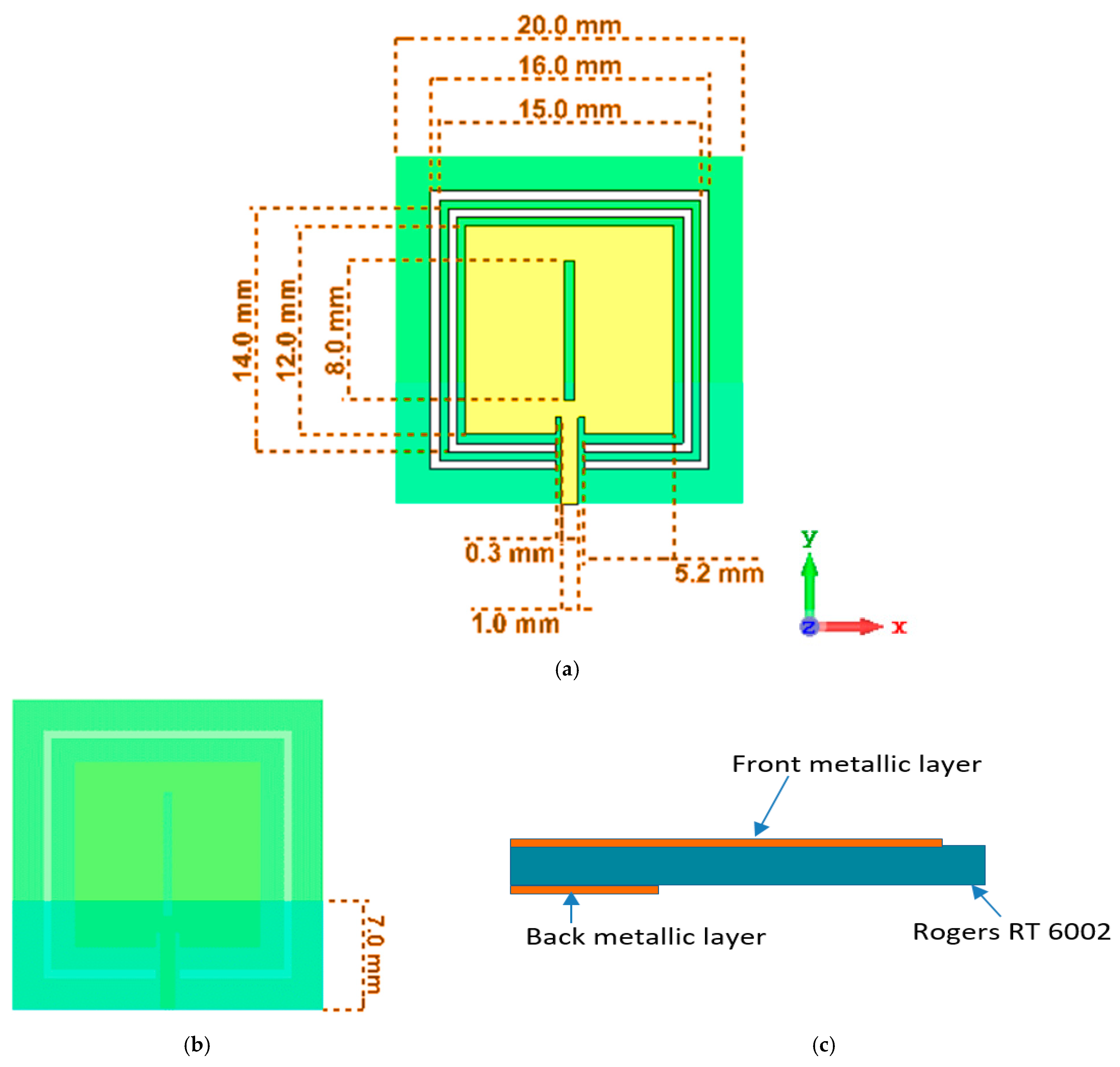
2. Metamaterial-Based Sensor Configuration
3. Methodology
3.1. Metamaterial Unit Cell
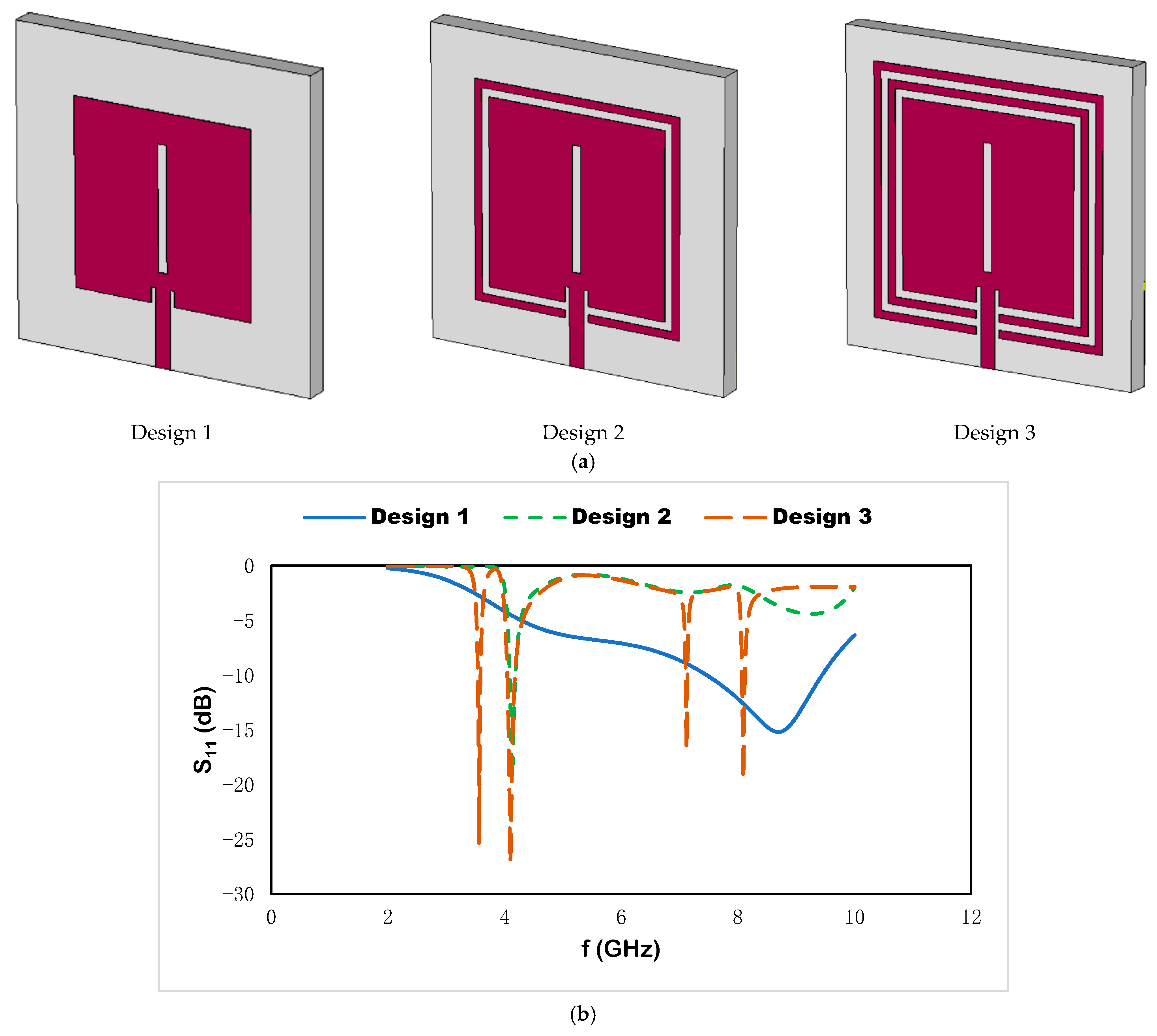
3.2. Metamaterial-Based Sensor
3.3. Effective Parameter
4. Results and Discussion
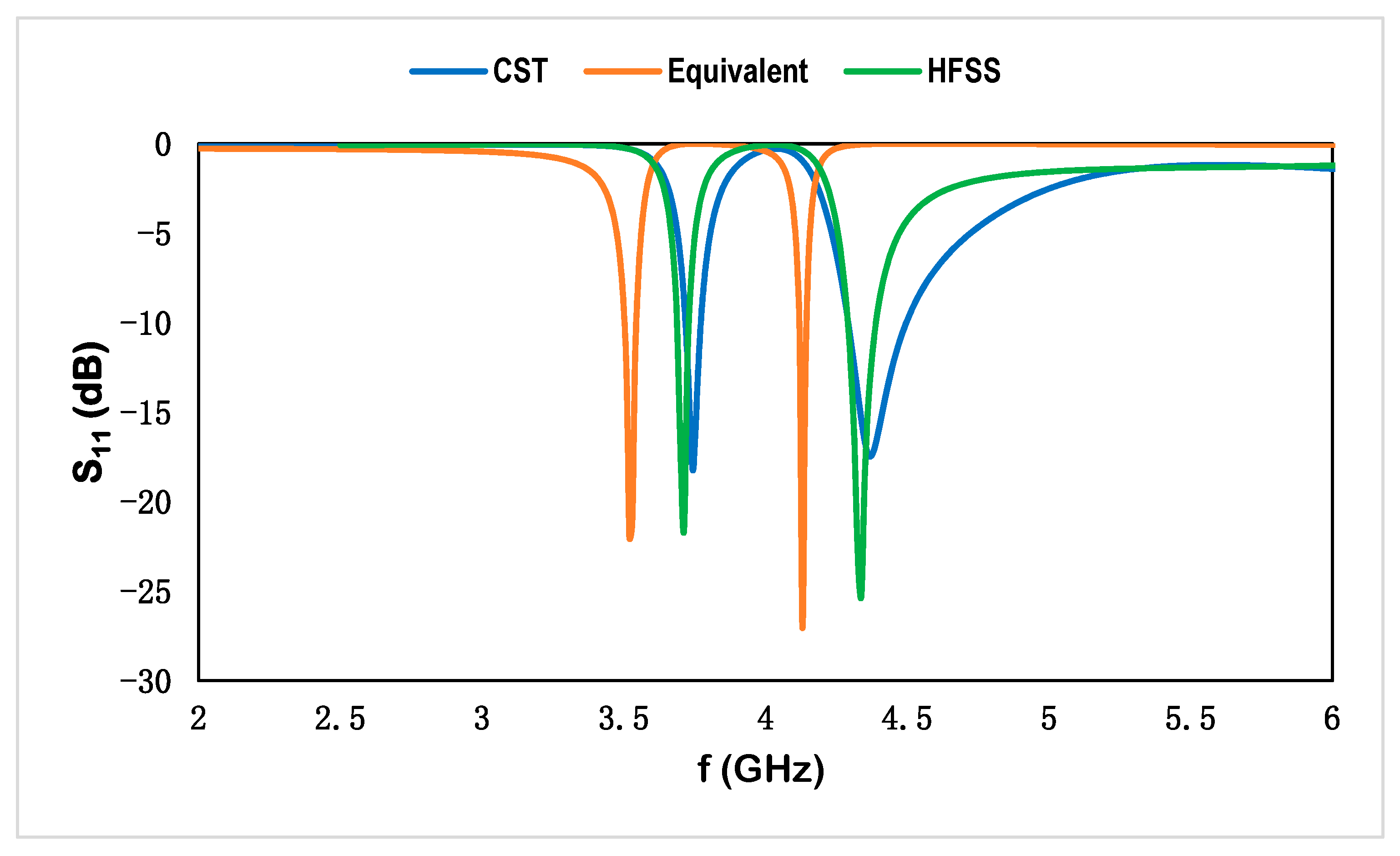
4.1. Results of Effective Properties for the Metamaterial Unit Cell
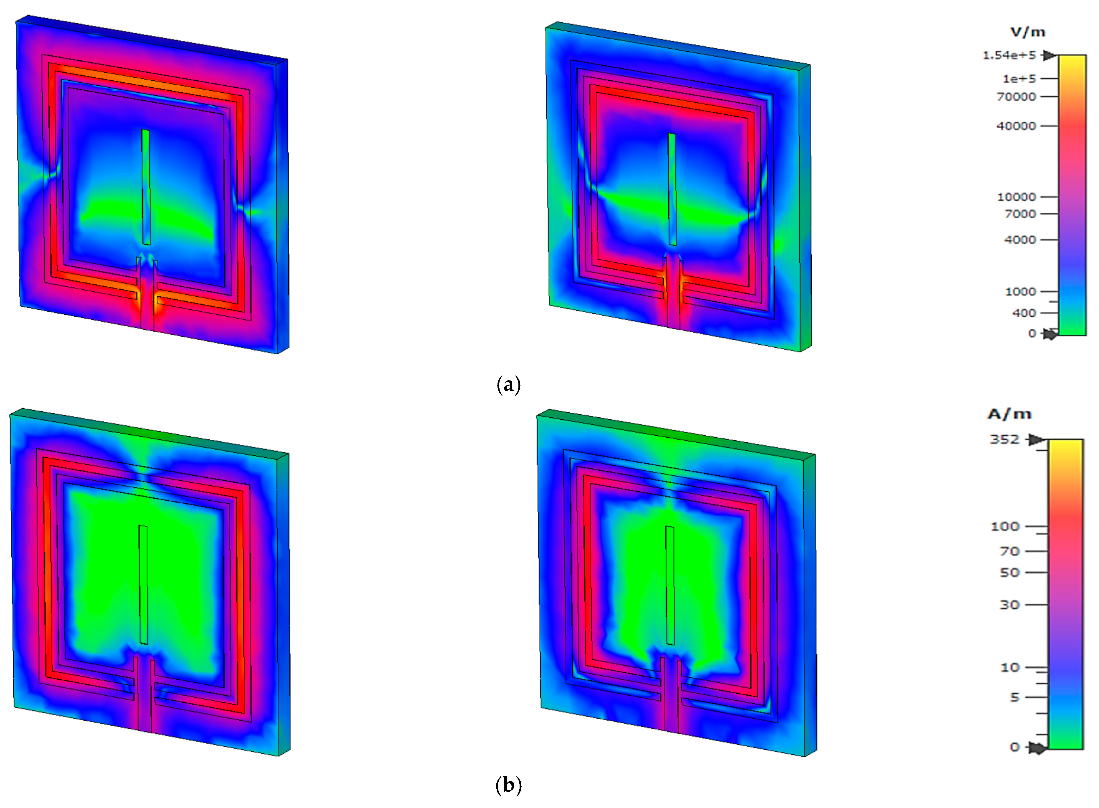
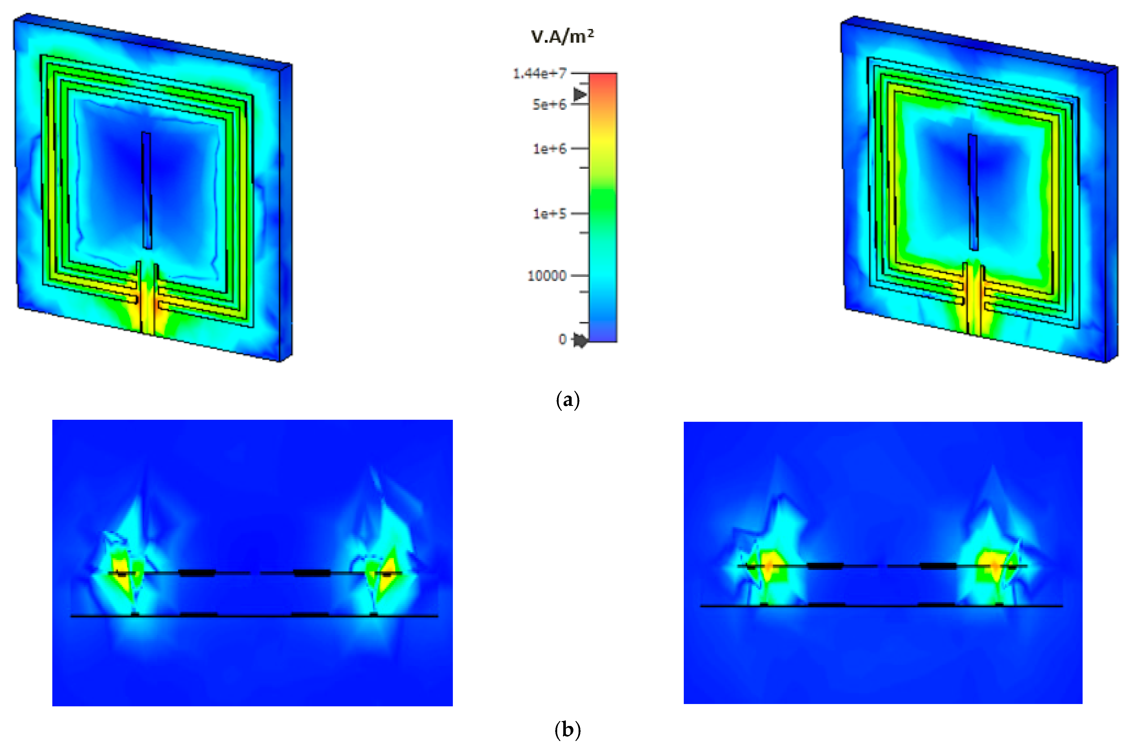
4.2. Electric and Magnetic Field, Surface Current, and Power Flow Distribution
4.3. Radiation and Dispersive Properties
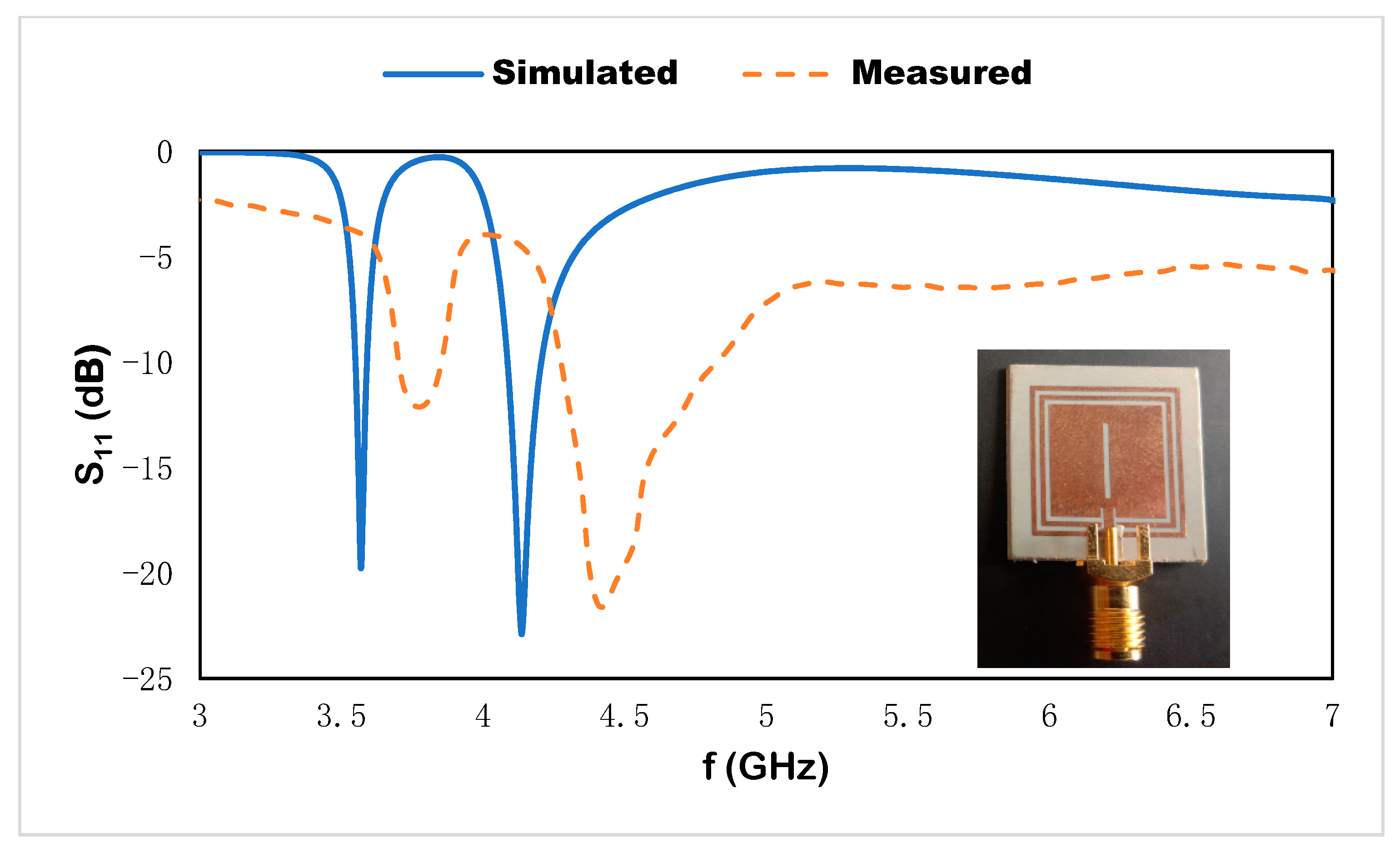
4.4. Simulated and Measured Result
5. Parametric Analysis
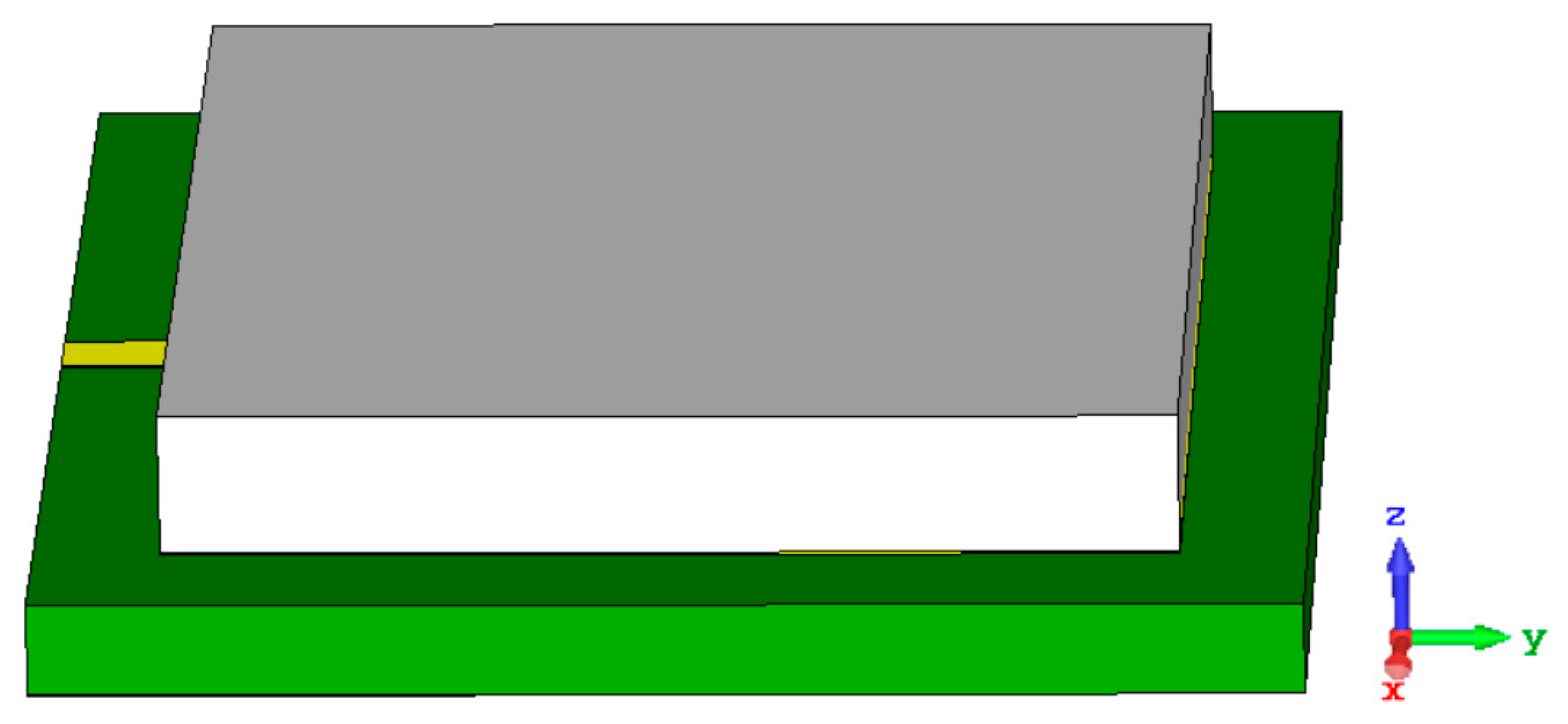
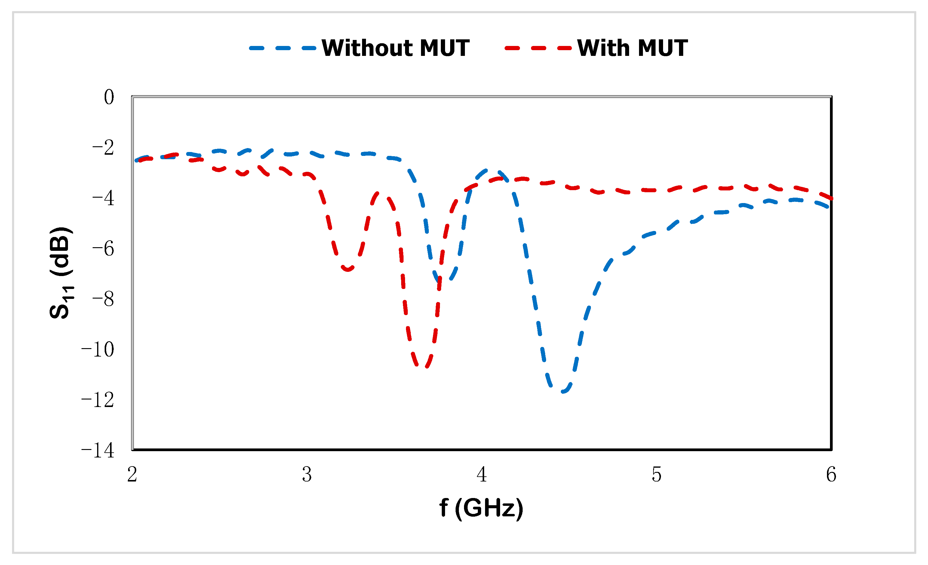
6. Microstrip-Based Sensor with MUT
7. Conclusions
Author Contributions
Funding
Data Availability Statement
Acknowledgments
Conflicts of Interest
References
- Liu, W.; Sun, H.; Xu, L. A microwave method for dielectric characterization measurement of small liquids using a metamaterial-based sensor. Sensors 2018, 18, 1438. [Google Scholar] [CrossRef] [PubMed] [Green Version]
- Xu, H.X.; Wang, G.M.; Zhang, C.X. Fractal-shaped metamaterials and applications to enhanced-performance devices exhibiting high selectivity. Int. J. Antennas Propag. 2012, 2012, 515167. [Google Scholar] [CrossRef] [Green Version]
- Mohammad, S.A.; Faruque, M.R.I.; Islam, M.T. Double H-shaped complementary split ring resonator with different orientations for quad-band satellite applications. Results Phys. 2020, 19, 103427. [Google Scholar]
- Iqbal, F.M.R.; Islam, M.T.; Misran, N. Design analysis of new metamaterial for EM absorption reduction. Prog. Electromagn. Res. 2012, 124, 119–135. [Google Scholar]
- Islam, S.S.; Faruque, M.R.; Islam, M.T. The design and analysis of a novel split-H-shaped metamaterial for multi-band microwave applications. Materials 2014, 7, 4994–5011. [Google Scholar] [CrossRef] [PubMed] [Green Version]
- Siddiky, A.M.; Faruque, M.R.; Abdullah, S.; Islam, M.T.; Nebhen, J. The circularly bent split ring resonator with a high effective medium ratio for multi frequency satellite band applications. J. Magn. Magn. Mater. 2022, 557, 169464. [Google Scholar] [CrossRef]
- Siddiky, A.M.; Faruque, M.R.I.; Abdullah, S.; Islam, M.T.; Khandaker, M.U.; Al-Mugren, K.S. Dual square split ring enclosed spiral shaped hybrid metamaterial resonator with size miniaturisation for microwave wireless applications. Sci. Rep. 2022, 12, 8028. [Google Scholar] [CrossRef]
- Ali, A.; Mitra, A.; Aïssa, B. Metamaterials and Metasurfaces: A Review from the Perspectives of Materials, Mechanisms and Advanced Metadevices. Nanomaterials 2022, 12, 1027. [Google Scholar] [CrossRef]
- Shahzad, W.; Hu, W.; Ali, Q.; Raza, H.; Abbas, S.M.; Ligthart, L.P. A Low-cost metamaterial sensor based on DS-CSRR for material characterization applications. Sensors 2022, 22, 2000. [Google Scholar] [CrossRef]
- Mosbah, S.; Zebiri, C.; Sayad, D.; Elfergani, I.; Bouknia, M.L.; Mekki, S.; Zegadi, R.; Palandoken, M.; Rodriguez, J.; Abd-Alhameed, R.A. Compact and Highly Sensitive Bended Microwave Liquid Sensor Based on a Metamaterial Complementary Split-Ring Resonator. Appl. Sci. 2022, 12, 2144. [Google Scholar] [CrossRef]
- Kim, Y.; Kim, H.; Yang, Y.; Badloe, T.; Jeon, N.; Rho, J. Three-dimensional artificial chirality towards low-cost and ultra-sensitive enantioselective sensing. Nanoscale 2022, 14, 3720–3730. [Google Scholar] [CrossRef] [PubMed]
- Zhao, W.; Wang, J.; Li, R.; Zhang, B. Ultranarrow dual-band metamaterial perfect absorber and its sensing application. J. Opt. 2022, 24, 035103. [Google Scholar] [CrossRef]
- Malena, L.; Fiser, O.; Stauffer, P.R.; Drizdal, T.; Vrba, J.; Vrba, D. Feasibility evaluation of metamaterial microwave sensors for non-invasive blood glucose monitoring. Sensors 2021, 21, 6871. [Google Scholar] [CrossRef] [PubMed]
- Harnsoongnoen, S. Metamaterial-inspired microwave sensor for detecting the concentration of mixed phosphate and nitrate in water. IEEE Trans. Instrum. Meas. 2021, 70, 1–6. [Google Scholar] [CrossRef]
- Dalgac, S.; Akdogan, V.; Kiris, S.; Incesu, A.; Akgol, O.; Unal, E.; Basar, M.T.; Karaaslan, M. Investigation of methanol contaminated local spirit using metamaterial based transmission line sensor. Measurement 2021, 178, 109360. [Google Scholar] [CrossRef]
- Lee, W.; Choi, S.; Kim, H.; Hwang, S.; Jeon, S.; Yoon, Y. Metamaterial-integrated high-gain rectenna for RF sensing and energy harvesting applications. Sensors 2021, 21, 6580. [Google Scholar] [CrossRef]
- Bahl, I.; Bhartia, P. Microwave Solid State Circuit Design; Wiley-Interscience: Hoboken, NJ, USA, 2003. [Google Scholar]
- James, R.; Hall, P.S.; Wood, C. Microstrip Antenna: Theory and Design; IET: London, UK, 1986; Volume 12. [Google Scholar]
- Chen, X.; Grzegorczyk, T.M.; Wu, B.I.; Pacheco, J., Jr.; Kong, J.A. Robust method to retrieve the constitutive effective parameters of metamaterials. Phys. Rev. E 2004, 70, 016608. [Google Scholar] [CrossRef] [Green Version]
- Saadat-Safa, M.; Nayyeri, V.; Ghadimi, A.; Soleimani, M.; Ramahi, O.M. A pixelated microwave near-field sensor for precise characterization of dielectric materials. Sci. Rep. 2019, 9, 13310. [Google Scholar] [CrossRef] [Green Version]
- Ebrahimi, A.; Scott, J.; Ghorbani, K. Microwave reflective biosensor for glucose level detection in aqueous solutions. Sens. Actuators A Phys. 2020, 301, 111662. [Google Scholar] [CrossRef]
- Alahnomi, R.; Binti, N.; Hamid, A.; Zakaria, Z.; Sutikno, T.; Azuan, A. Microwave planar sensor for permittivity determination of dielectric materials. Indones J. Electr. Eng. Comput. Sci. 2018, 11, 362–371. [Google Scholar] [CrossRef]
- Crupi, G.; Bao, X.; Babarinde, O.J.; Schreurs, D.M.M.-P.; Nauwelaers, B. Biosensor using a one-port interdigital capacitor: A resonance-based investigation of the permittivity sensitivity for microfluidic broadband bioelectronics applications. Electronics 2020, 9, 340. [Google Scholar] [CrossRef]


| Parameter | Length of the Outer Split Ring | Length of the Inner Split Ring | Width of the Outer Split Ring | Width of the Inner Split Ring | Cut Width in Microstrip Patch | Cut Depth of the Patch | Length of the Patch | Width of the Feed Line |
|---|---|---|---|---|---|---|---|---|
| mm | 16 | 14 | 0.5 | 0.5 | 5.2 | 0.3 | 12 | 1 |
| Resonant Frequency at 3.56 GHz | Resonant Frequency at 4.14 GHz | |
|---|---|---|
| Radiation efficiency | −1.224 | −0.3826 |
| Total radiation efficiency | −1.270 | −0.4056 |
| Gain | 2.092 | 2.819 |
| Realized gain | 2.047 | 2.797 |
| Radiation plot | 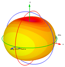 |  |
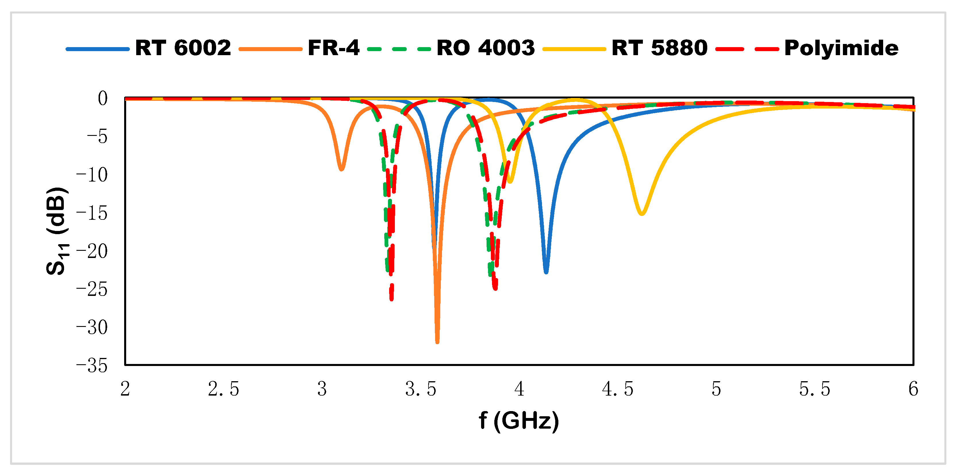
| Dielectric Constant | Resonant Frequencies | Depth Notch | |
|---|---|---|---|
| FR-4 | 4.3 | 3.11, 3.6 | −9.4, −32 |
| Rogers RT 5880 | 2.2 | 3.94, 4.6 | −11.5, −15.3 |
| Rogers RO 4003 | 3.55 | 3.33, 3.84 | −22.84, −24.24 |
| Polyimide | 3.5 | 3.4, 3.88 | −26.32, −25.10 |
| Rogers RT 6002 | 2.94 | 3.56, 4.14 | −19.8, −23 |
| First Resonant Peak | Second Resonant Peak | Sensitivity | |
|---|---|---|---|
| εr = 1 | 3.56 | 4.14 | - |
| εr = 1.5 | 3.44 | 3.91 | 235 |
| εr = 2 | 3.29 | 3.74 | 450 |
| εr = 2.5 | 3.14 | 3.58 | 660 |
| εr = 3 | 3.03 | 3.46 | 860 |
| εr = 3.5 | 2.92 | 3.32 | 1000 |
| εr = 4 | 2.83 | 3.22 | 1170 |
| Linear Regression Plot | Linear Regression Equation | R2 |
|---|---|---|
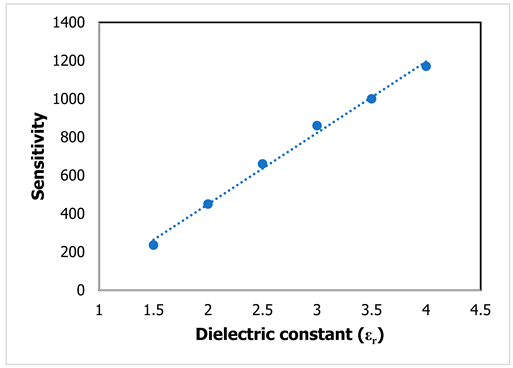 | y = 372.86x − 296.19 | R2 = 0.9943 |
| [20] | [21] | [22] | [23] | Proposed | |
|---|---|---|---|---|---|
| Substrate | Rogers RO 4003 | RO 4350 | Rogers 5880 | Quartz | Rogers RT 6002 |
| Type | Pixelated CSRR based microstrip | CSRR based microstrip | Closed ring patch | Coplanar interdigital capacitor | Dual SRR enclosed microstrip |
| Number of ports | two | single | single | single | single |
| Design simplicity | medium | medium | simple | medium | simple |
| Sensitivity parameter | S21 | S11 | S11 | Impedance | S11 |
| Dimension (mm2) | 50 × 50 | 30 × 25 | 38.69 × 68.12 | 0.3 × 0.7 | 20 × 20 |
| Operating frequency range (GHz) | 3–6 | 2.45–2.55 | 3.6–4.0 | 20–24 | 2.7–8.4 |
| Number of resonance frequency | 1 | 1 | 1 | 1 | 2 |
| Compactness ratio (λ/D) | 1.07 | 3.07 | 1.03 | 1.7 | 3.57 |
| Year | 2019 | 2020 | 2018 | 2020 | 2022 |
Publisher’s Note: MDPI stays neutral with regard to jurisdictional claims in published maps and institutional affiliations. |
© 2022 by the authors. Licensee MDPI, Basel, Switzerland. This article is an open access article distributed under the terms and conditions of the Creative Commons Attribution (CC BY) license (https://creativecommons.org/licenses/by/4.0/).
Share and Cite
Siddiky, A.M.; Faruque, M.R.I.; Islam, M.T.; Abdullah, S.; Khandaker, M.U.; Al-Mugren, K.S. Dual-Square-Split-Ring-Enclosed Microstrip-Based Sensor for Noninvasive Label-Free Detection. Materials 2022, 15, 7688. https://doi.org/10.3390/ma15217688
Siddiky AM, Faruque MRI, Islam MT, Abdullah S, Khandaker MU, Al-Mugren KS. Dual-Square-Split-Ring-Enclosed Microstrip-Based Sensor for Noninvasive Label-Free Detection. Materials. 2022; 15(21):7688. https://doi.org/10.3390/ma15217688
Chicago/Turabian StyleSiddiky, Air Mohammad, Mohammad Rashed Iqbal Faruque, Mohammad Tariqul Islam, Sabirin Abdullah, Mayeen Uddin Khandaker, and K. S. Al-Mugren. 2022. "Dual-Square-Split-Ring-Enclosed Microstrip-Based Sensor for Noninvasive Label-Free Detection" Materials 15, no. 21: 7688. https://doi.org/10.3390/ma15217688