
Texturing Methods of Abrasive Grinding Wheels: A Systematic Review


Abstract
:1. Introduction
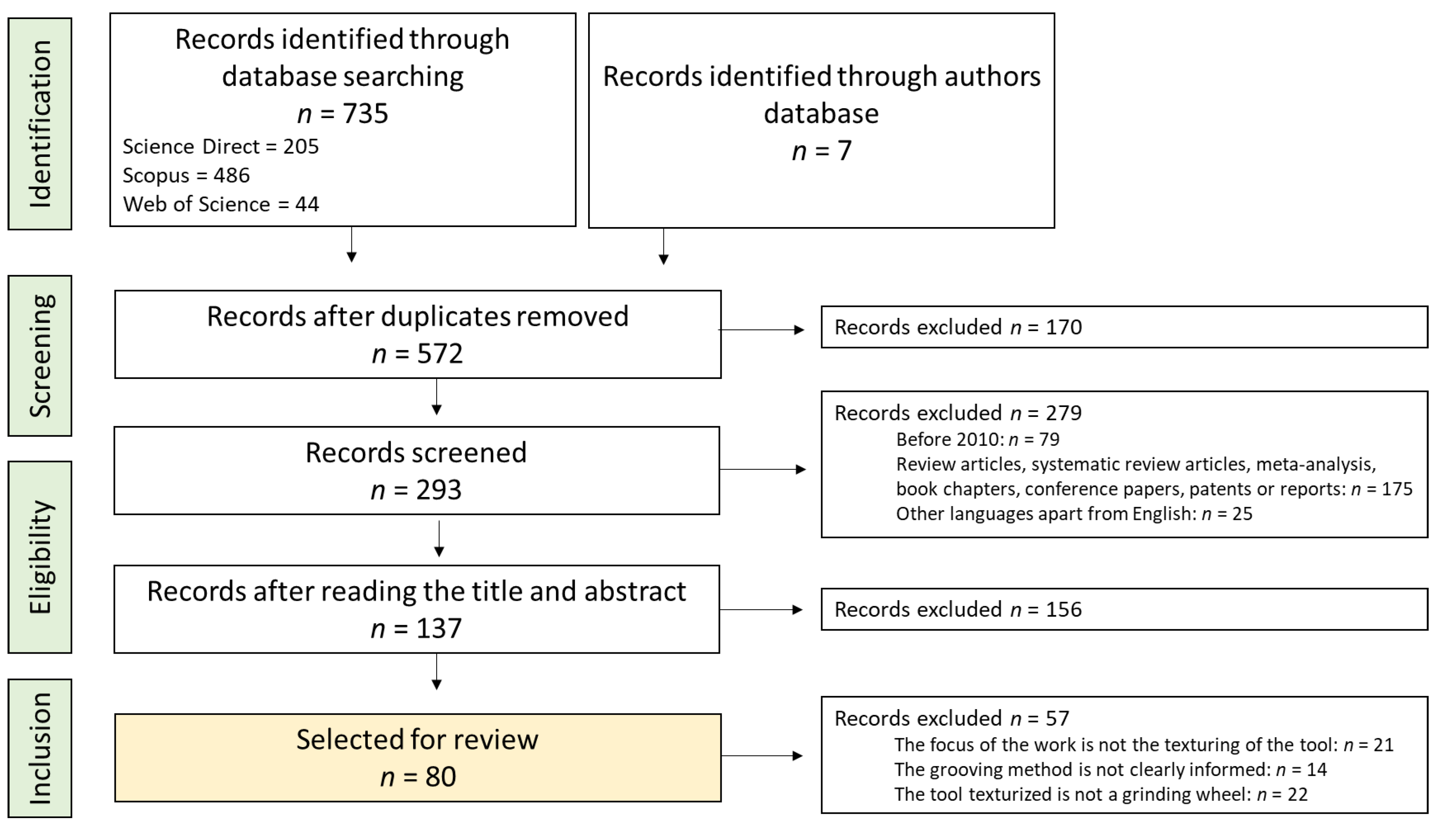
2. Methods
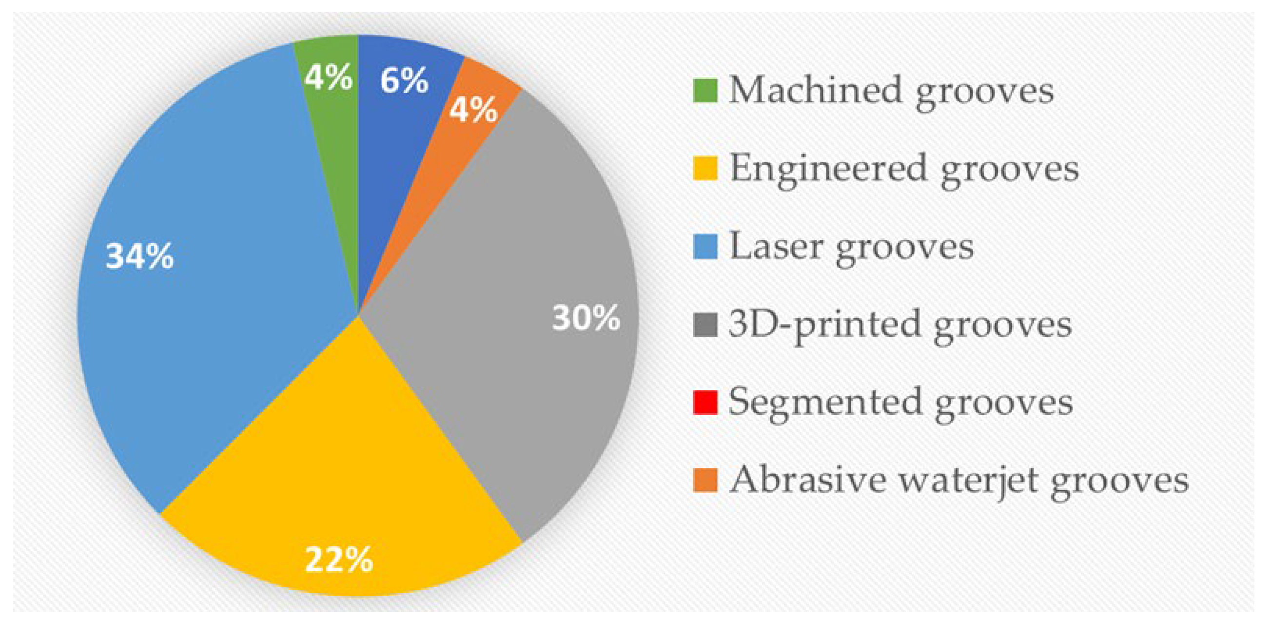
3. Results
4. Discussion
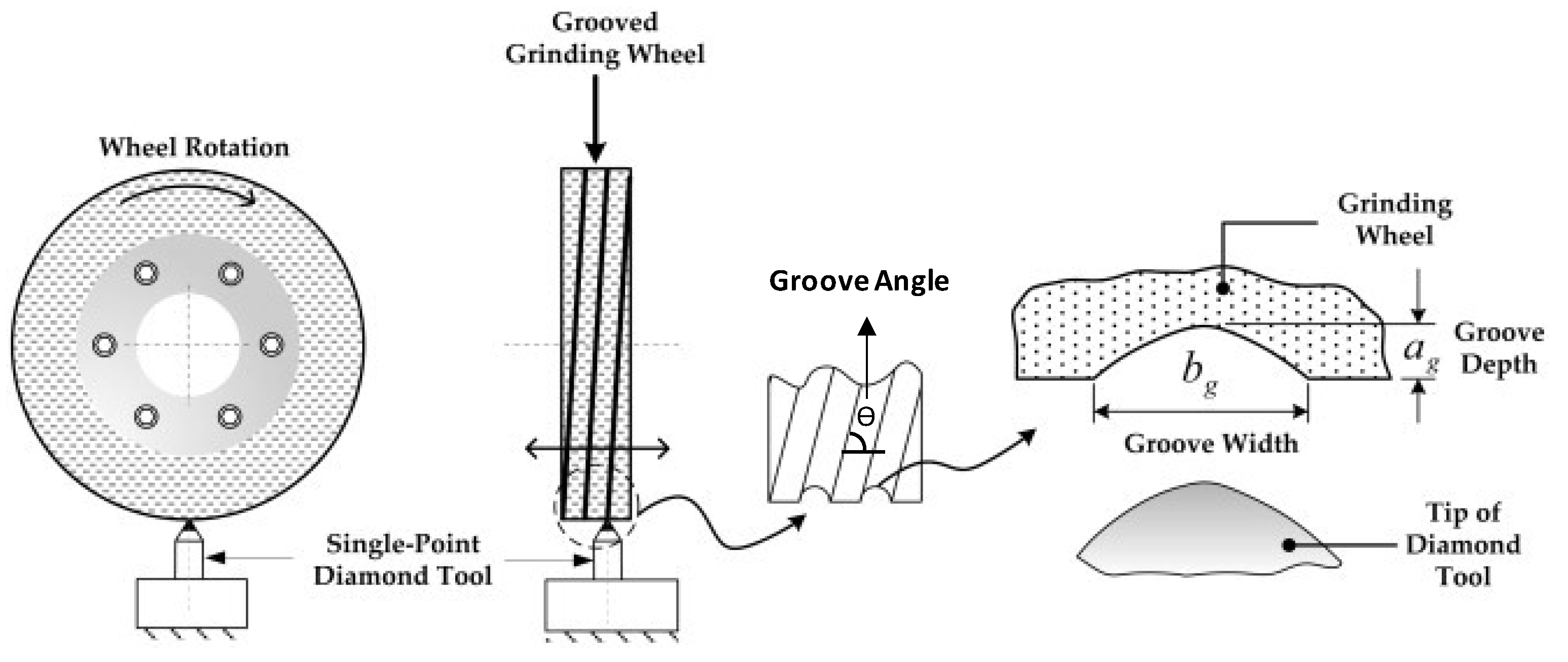
4.1. Machined Grooves
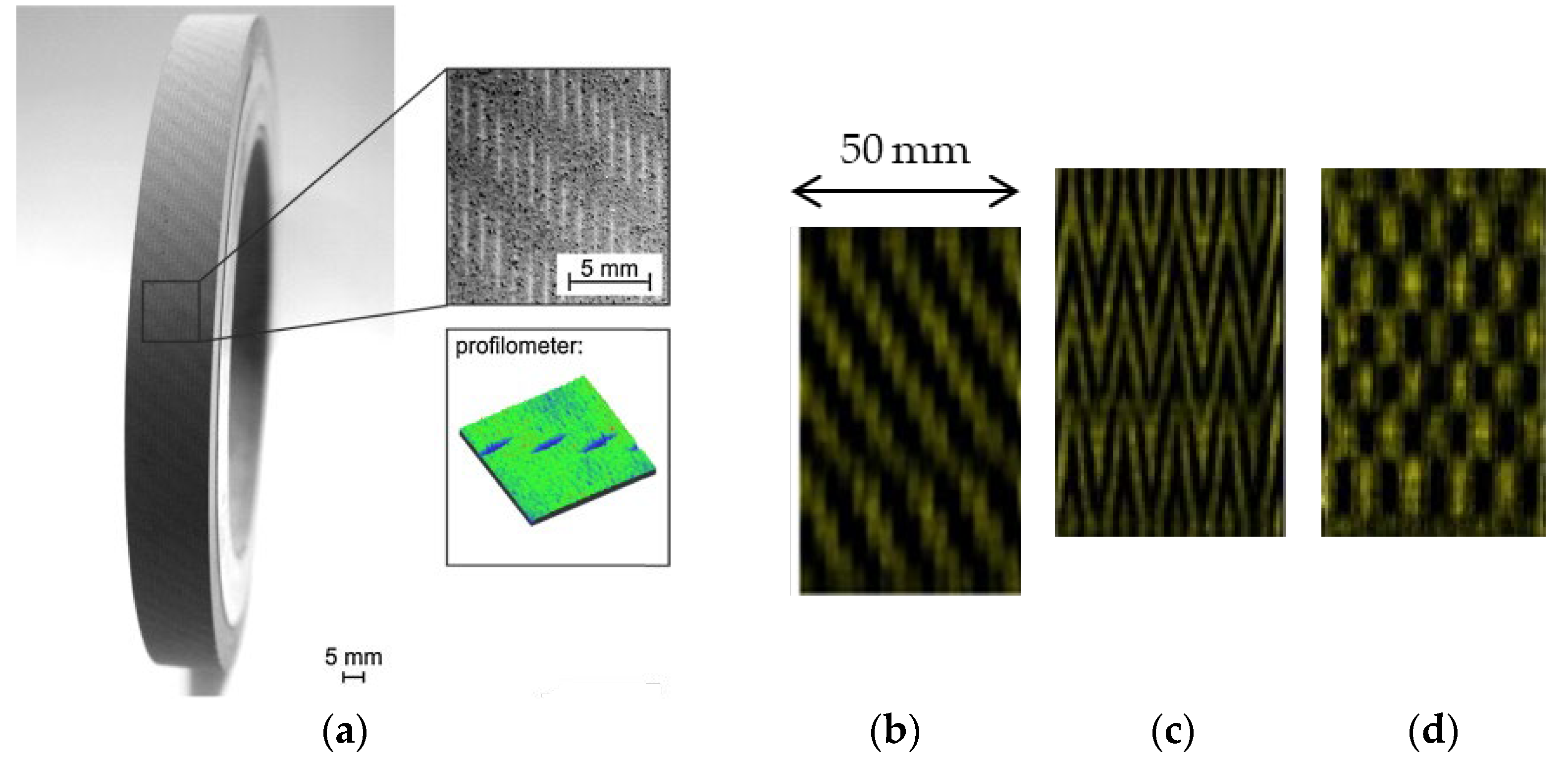
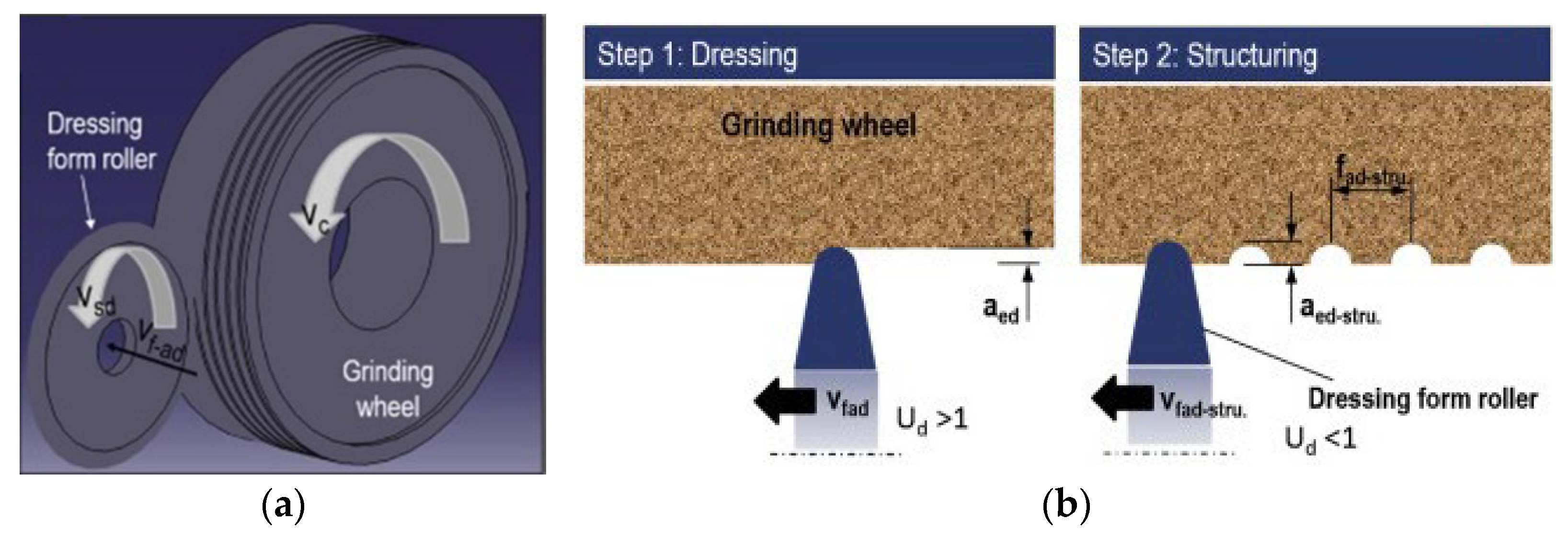
4.2. Engineered Grooves
4.3. Laser Grooves
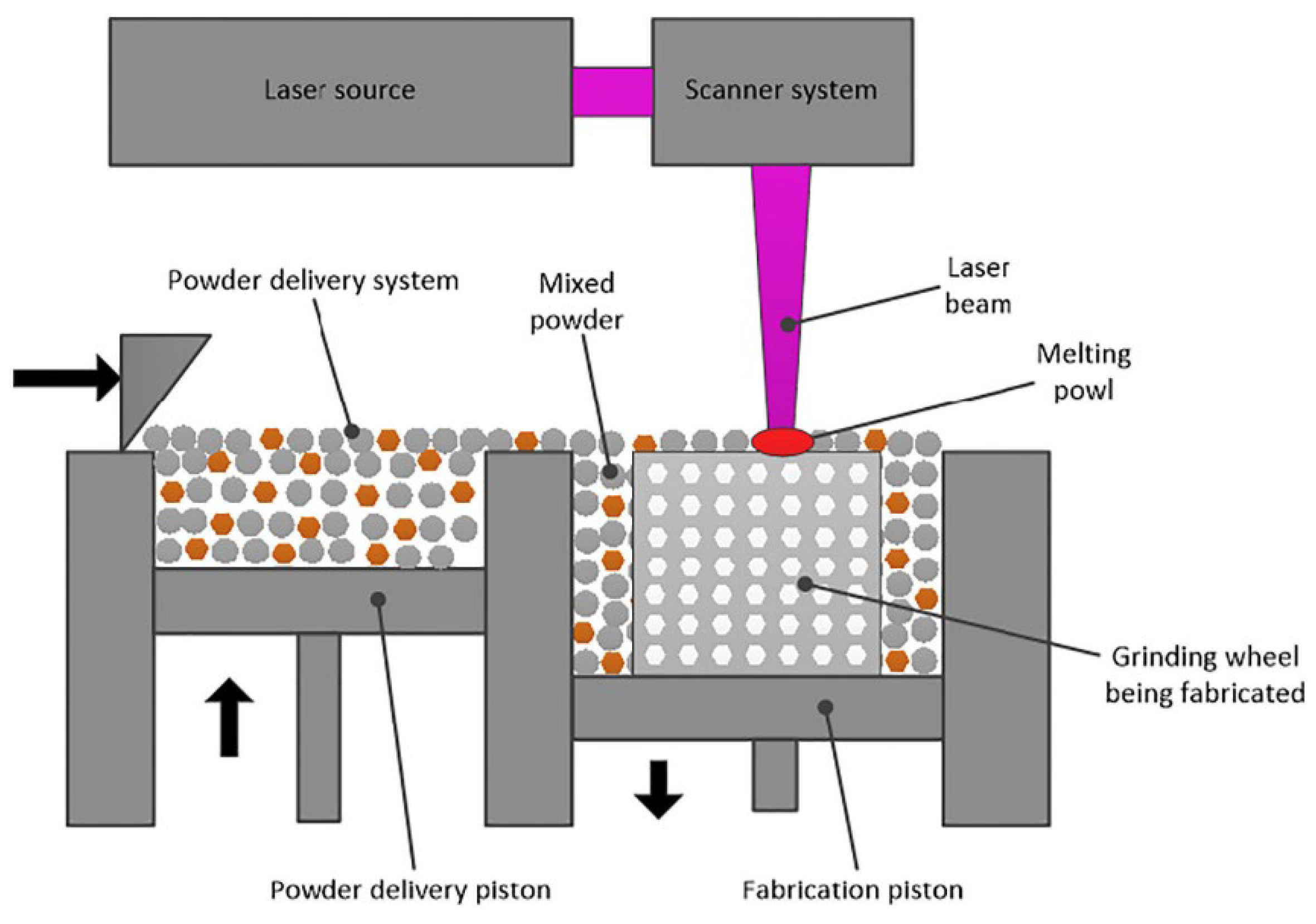
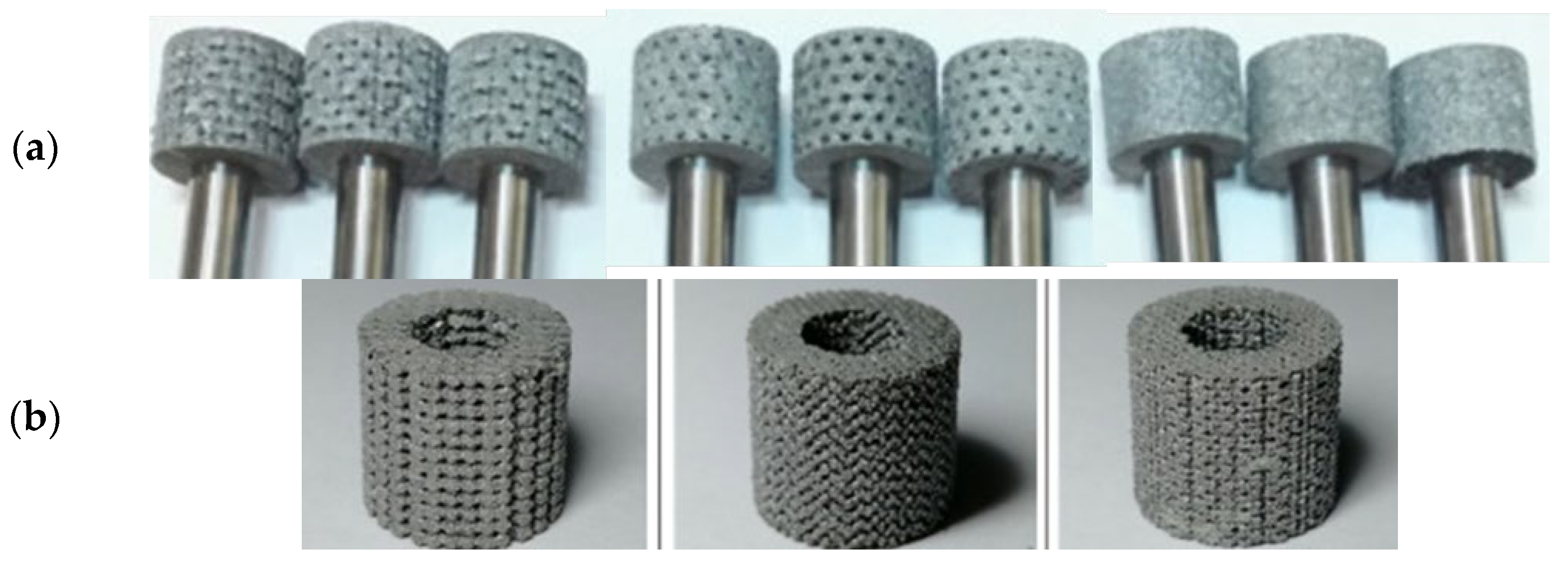
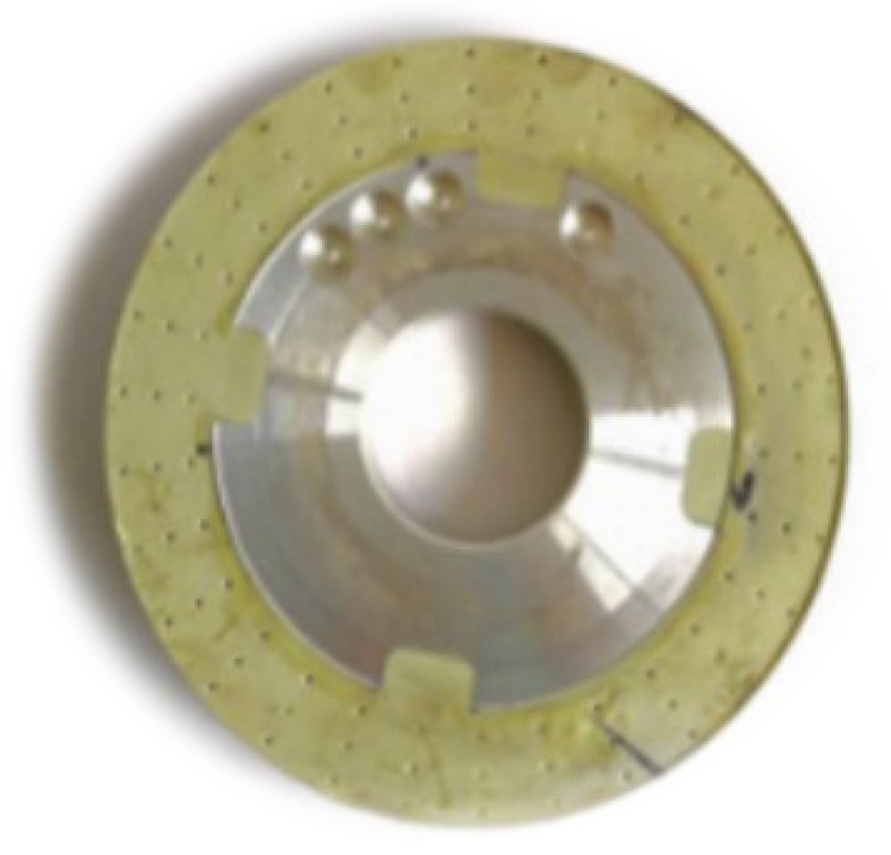
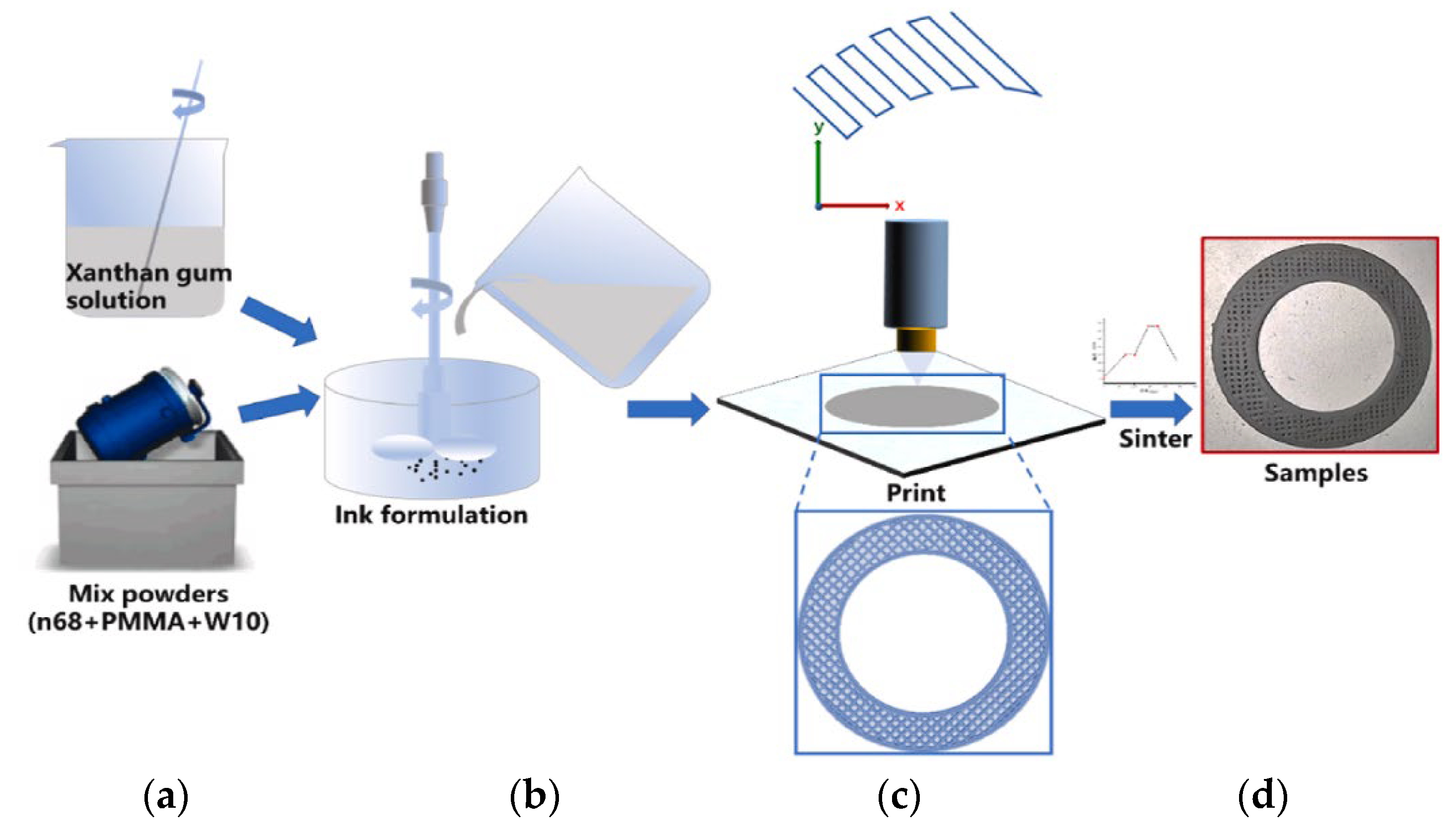
4.4. 3D-Printed Grooves
4.5. Segmented Grooves
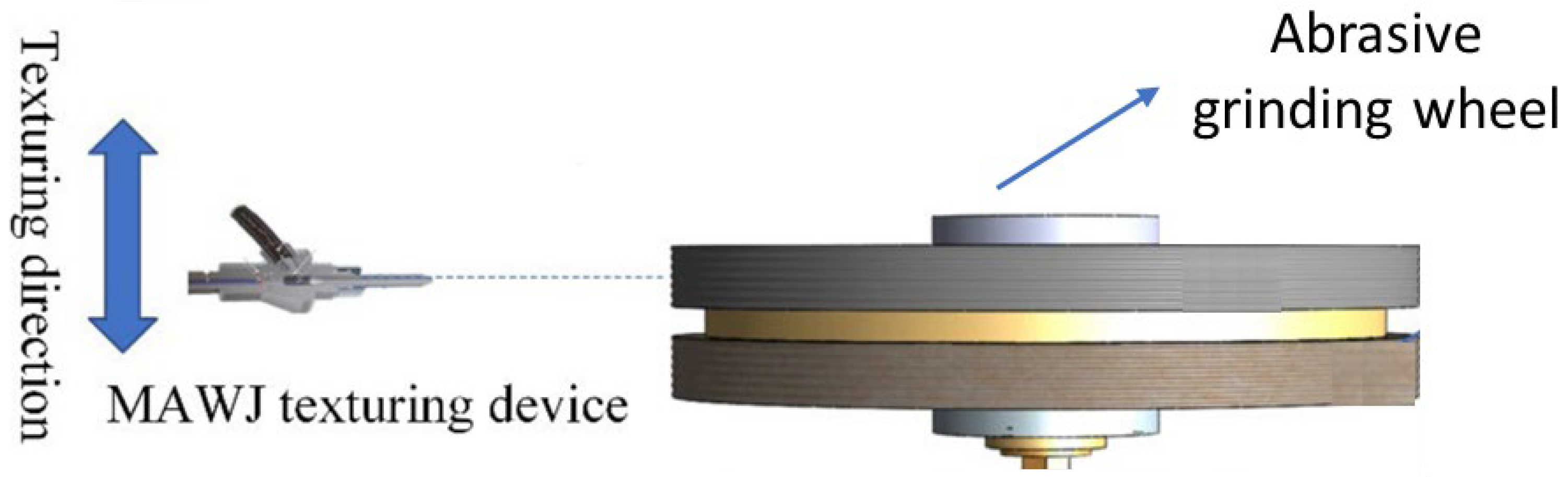
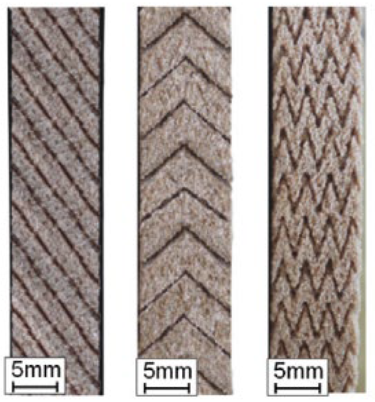
4.6. Abrasive Waterjet
5. Conclusions
- (a)
- In recent years, new texturing methods have gained attention (such as additive manufacturing production techniques), while the number of publications on machined grooves has been decreasing since 2018.
- (b)
- Among all the methods evaluated in this work, the engineered groove process is the one that has been demonstrated to be able to produce the most complex grooves. However, the application of the method is limited to monolayer grinding wheels. For wheels that are not monolayers, the laser method is the most suitable for producing grooves with greater geometric control. Furthermore, unlike machining techniques, the laser method has the advantage that the tool that produces the grooves does not wear out.
- (c)
- In general, methods for making textured abrasive wheels are constantly in evolution; more and more innovative geometries and techniques have been studied and proposed. However, there is still a marked gap in the manufacture of abrasive wheels with three-dimensional channel structures, showing the technological difficulty. Almost all the techniques used until now only produce superficial grooves, that is, after the grinding wheel wears out, a new operation is necessary to refashion the grooves. Additive manufacturing is a method capable of producing internal channels; however, it is an expensive process and without industrial application feasibility for series production.
- (d)
- For future work, it is suggested to explore the AWJ method, which, like the laser method, has the advantage of the absence of tool wear; however, there are still few publications on the subject. Three-dimensional grooves also represent a very promising field for future work. A technique capable of producing three-dimensional, textured, abrasive wheels in a simple and controlled manner has not yet been developed.
Author Contributions
Funding
Institutional Review Board Statement
Informed Consent Statement
Data Availability Statement
Conflicts of Interest
References
- Bazan, A.; Kawalec, A.; Rydzak, T.; Kubik, P. Variation of Grain Height Characteristics of Electroplated CBN Grinding-Wheel Active Surfaces Associated with Their Wear. Metals 2020, 10, 1479. [Google Scholar] [CrossRef]
- Gołąbczak, M.; Święcik, R.; Gołąbczak, A.; Kaczmarek, D.; Dębkowski, R.; Tomczyk, B. Electrodischarge Methods of Shaping the Cutting Ability of Superhard Grinding Wheels. Materials 2021, 14, 6773. [Google Scholar] [CrossRef] [PubMed]
- El-Hofy, H. Fundamentals of Machining Processes: Conventional and Nonconventional Processes, 3rd ed.; CRC Press: Boca Raton, FL, USA, 2018; ISBN 9780429443329. [Google Scholar]
- Nadolny, K.; Kieraś, S. Experimental Studies on the Centrifugal MQL-CCA Method of Applying Coolant during the Internal Cylindrical Grinding Process. Materials 2020, 13, 2383. [Google Scholar] [CrossRef] [PubMed]
- Zhang, X.; Wen, D.; Shi, Z.; Li, S.; Kang, Z.; Jiang, J.; Zhang, Z. Grinding Performance Improvement of Laser Micro-Structured Silicon Nitride Ceramics by Laser Macro-Structured Diamond Wheels. Ceram. Int. 2020, 46, 795–802. [Google Scholar] [CrossRef]
- Nguyen, T.; Zhang, L.C. Performance of a New Segmented Grinding Wheel System. Int. J. Mach. Tools Manuf. 2009, 49, 291–296. [Google Scholar] [CrossRef]
- Groover, M.P. Fundamentals of Modern Manufacturing: Materials, Processes, and Systems, 7th ed.; John Wiley & Sons: Hoboken, NJ, USA, 2020; ISBN 978-1-119-47529-3. [Google Scholar]
- Li, H.N.; Axinte, D. Textured Grinding Wheels: A Review. Int. J. Mach. Tools Manuf. 2016, 109, 8–35. [Google Scholar] [CrossRef]
- Uhlmann, E.; Muthulingam, A. Optimizing the Sharpening Process of Hybrid-Bonded Diamond Grinding Wheels by Means of a Process Model. Machines 2021, 10, 8. [Google Scholar] [CrossRef]
- Bazan, A.; Kawalec, A.; Rydzak, T.; Kubik, P.; Olko, A. Determination of Selected Texture Features on a Single-Layer Grinding Wheel Active Surface for Tracking Their Changes as a Result of Wear. Materials 2020, 14, 6. [Google Scholar] [CrossRef]
- AN, Q.; CHEN, J.; MING, W.; CHEN, M. Machining of SiC Ceramic Matrix Composites: A Review. Chin. J. Aeronaut. 2021, 34, 540–567. [Google Scholar] [CrossRef]
- Li, C.; Li, X.; Huang, S.; Li, L.; Zhang, F. Ultra-Precision Grinding of Gd3Ga5O12 Crystals with Graphene Oxide Coolant: Material Deformation Mechanism and Performance Evaluation. J. Manuf. Process. 2021, 61, 417–427. [Google Scholar] [CrossRef]
- Gao, T.; Li, C.; Yang, M.; Zhang, Y.; Jia, D.; Ding, W.; Debnath, S.; Yu, T.; Said, Z.; Wang, J. Mechanics Analysis and Predictive Force Models for the Single-Diamond Grain Grinding of Carbon Fiber Reinforced Polymers Using CNT Nano-Lubricant. J. Mater. Process. Technol. 2021, 290, 116976. [Google Scholar] [CrossRef]
- Ge, M.; Ji, S.; Tan, D.; Cao, H. Erosion Analysis and Experimental Research of Gas-Liquid-Solid Soft Abrasive Flow Polishing Based on Cavitation Effects. Int. J. Adv. Manuf. Technol. 2021, 114, 3419–3436. [Google Scholar] [CrossRef]
- Ge, J.; Li, C.; Gao, Z.; Ren, Y.; Xu, X.; Li, C.; Xie, Y. Softness Abrasive Flow Polishing Method Using Constrained Boundary Vibration. Powder Technol. 2021, 382, 173–187. [Google Scholar] [CrossRef]
- Brinksmeier, E.; Karpuschewski, B.; Yan, J.; Schönemann, L. Manufacturing of Multiscale Structured Surfaces. CIRP Ann. 2020, 69, 717–739. [Google Scholar] [CrossRef]
- Jin, D.X.; Meng, Z. Research for Discontinuous Grinding Wheel with Multi-Porous Grooves. Key Eng. Mater. 2004, 259–260, 117–121. [Google Scholar] [CrossRef]
- Kim, J.D.; Kang, Y.H.; Jin, D.X.; Lee, Y.S. Development of Discontinuous Grinding Wheel with Multi-Porous Grooves. Int. J. Mach. Tools Manuf. 1997, 37, 1611–1624. [Google Scholar] [CrossRef]
- Scrivener, A. Means for Shaping the Operative Surfaces of Grinding Wheels. US Patent 2,135,202, 29 October 1938. [Google Scholar]
- Sherk, H.E. Slotted Abrasive Wheel. U.S. Patent US2049874, 4 August 1936. [Google Scholar]
- De Graaff, W.T. Grinding Wheel Having Dead End Grooves and Method for Grinding Therewith. U.S. Patent 5611724A, 18 March 1997. [Google Scholar]
- Nakayama, K.; Takagi, J.; Abe, T. Grinding Wheel with Helical Grooves-an Attempt to Improve the Grinding Performance. CIRP Ann. 1977, 25, 133–138. [Google Scholar]
- Zhang, G.; Deng, X.; Liu, D.; Song, T. A Nano-MQL Grinding of Single-Crystal Nickel-Base Superalloy Using a Textured Grinding Wheel. Int. J. Adv. Manuf. Technol. 2022, 121, 2787–2801. [Google Scholar] [CrossRef]
- Forbrigger, C.; Bauer, R.; Warkentin, A. A Review of State-of-the-Art Vitrified Bond Grinding Wheel Grooving Processes. Int. J. Adv. Manuf. Technol. 2016, 90, 2207–2216. [Google Scholar] [CrossRef]
- Page, M.J.; McKenzie, J.E.; Bossuyt, P.M.; Boutron, I.; Hoffmann, T.C.; Mulrow, C.D.; Shamseer, L.; Tetzlaff, J.M.; Akl, E.A.; Brennan, S.E.; et al. The PRISMA 2020 Statement: An Updated Guideline for Reporting Systematic Reviews. Int. J. Surg. 2021, 88, 105906. [Google Scholar] [CrossRef]
- Mohamed, A.M.O.; Bauer, R.; Warkentin, A. Application of Shallow Circumferential Grooved Wheels to Creep-Feed Grinding. J. Mater. Process. Technol. 2013, 213, 700–706. [Google Scholar] [CrossRef]
- Oliveira, J.F.G.; Bottene, A.C.; França, T.V. A Novel Dressing Technique for Texturing of Ground Surfaces. CIRP Ann. 2010, 59, 361–364. [Google Scholar] [CrossRef]
- Gavas, M.; Karacan, Ä.; Kaya, E. A Novel Method to Improve Surface Quality in Cylindrical Grinding. Exp. Tech. 2011, 35, 26–32. [Google Scholar] [CrossRef]
- Tawakoli, T.; Lee, D.H.; Rasifard, A. Dry Plunge Cylindrical Grinding Utilising Structured Grinding Wheel. Int. J. Mechatron. Manuf. Syst. 2012, 5, 154–164. [Google Scholar] [CrossRef]
- Aurich, J.C.; Kirsch, B. Improved Coolant Supply through Slotted Grinding Wheel. CIRP Ann. Manuf. Technol. 2013, 62, 363–366. [Google Scholar] [CrossRef]
- Nadolny, K. Micro-Discontinuities of the Grinding Wheel and Their Effects on Its Durability during Internal Cylindrical Grinding. Mach. Sci. Technol. 2013, 17, 74–92. [Google Scholar] [CrossRef]
- Silva, E.J.D.; de Oliveira, J.F.G.; Salles, B.B.; Cardoso, R.S.; Reis, V.R.A. Strategies for Production of Parts Textured by Grinding Using Patterned Wheels. CIRP Ann. 2013, 62, 355–358. [Google Scholar] [CrossRef]
- Köklü, U. Grinding with Helically Grooved Wheels. Proc. Inst. Mech. Eng. Part E J. Process. Mech. Eng. 2014, 228, 33–42. [Google Scholar] [CrossRef]
- Mohamed, A.-M.O.; Bauer, R.; Warkentin, A. A Novel Method for Grooving and Re-Grooving Aluminum Oxide Grinding Wheels. Int. J. Adv. Manuf. Technol. 2014, 73, 715–725. [Google Scholar] [CrossRef]
- Gavas, M.; Kỳna, M.; Köklü, U. Effects of Various Helically Angled Grinding Wheels on the Surface Roughness and Roundness in Grinding Cylindrical Surfaces. Mater. Technol. 2015, 49, 865–870. [Google Scholar] [CrossRef]
- Denkena, B.; Grove, T.; Göttsching, T. Grinding with Patterned Grinding Wheels. CIRP J. Manuf. Sci. Technol. 2015, 8, 12–21. [Google Scholar] [CrossRef]
- Denkena, B.; Grove, T.; Göttsching, T.; da Silva, E.J.; Coelho, R.T.; Filleti, R. Enhanced Grinding Performance by Means of Patterned Grinding Wheels. Int. J. Adv. Manuf. Technol. 2015, 77, 1935–1941. [Google Scholar] [CrossRef] [Green Version]
- Wójcik, R.; Nadolny, K. The Effect of the Grinding Wheel Modification on the State of the Workpiece Surface Layer after Internal Cylindrical Grinding of Steel C45. Proc. Inst. Mech. Eng. E J. Process. Mech. Eng. 2017, 231, 1162–1173. [Google Scholar] [CrossRef]
- Azarhoushang, B.; Daneshi, A.; Lee, D.H. Evaluation of Thermal Damages and Residual Stresses in Dry Grinding by Structured Wheels. J. Clean. Prod. 2017, 142, 1922–1930. [Google Scholar] [CrossRef]
- Caydas, U.; Çelk, M. Genetic Algorithm-Based Optimization for Surface Roughness in Cylindrically Grinding Process Using Helically Grooved Wheels. Surf. Rev. Lett. 2017, 24, 1850031. [Google Scholar] [CrossRef]
- Liu, Y.; Gong, S.; Li, J.; Cao, J. Effects of Dressed Wheel Topography on Patterned Surface Textures and Grinding Force. Int. J. Adv. Manuf. Technol. 2017, 93, 1751–1760. [Google Scholar] [CrossRef]
- Silva, E.J.; Kirsch, B.; Bottene, A.C.; Simon, A.; Aurich, J.C.; Oliveira, J.F.G. Manufacturing of Structured Surfaces via Grinding. J. Mater. Process. Technol. 2017, 243, 170–183. [Google Scholar] [CrossRef]
- Mohamed, A.L.-M.O.; Warkentin, A.; Bauer, R. Prediction of Workpiece Surface Texture Using Circumferentially Grooved Grinding Wheels. Int. J. Adv. Manuf. Technol. 2017, 89, 1149–1160. [Google Scholar] [CrossRef]
- Cao, H.; Chen, X.; Li, H. Dressing Strategy and Grinding Control for Cylindrical Microstructural Surface. Int. J. Adv. Manuf. Technol. 2018, 99, 707–727. [Google Scholar] [CrossRef] [Green Version]
- Daneshi, A.; Müller, K.; Azarhoushang, B. Cylindrical Plunge Grinding of Twist Free Surfaces by Structured Wheels. Precis. Eng. 2018, 51, 481–489. [Google Scholar] [CrossRef]
- Silva, E.J.D.; Marcos, G.P.; Venter, G.S.; Bottene, A.C.; Oliveira, J.F.G.D.; Rodrigues, C.A. Development of a Patterning System for Vitrified CBN Wheels Based on Modal Analysis. CIRP Ann. 2018, 67, 341–344. [Google Scholar] [CrossRef]
- Dewar, S.; Bauer, R.; Warkentin, A. Application of High-Angle Helical-Grooved Vitrified Wheels to Cylindrical Plunge Grinding. Int. J. Adv. Manuf. Technol. 2018, 96, 2443–2453. [Google Scholar] [CrossRef]
- Forbrigger, C.; Bauer, R.; Warkentin, A. Improving the Accuracy of a Profile Grinding Wheel Grooving Robot Attachment for a CNC Grinding Machine. Int. J. Adv. Manuf. Technol. 2018, 98, 3205–3216. [Google Scholar] [CrossRef]
- Forbrigger, C.; Warkentin, A.; Bauer, R. Improving the Performance of Profile Grinding Wheels with Helical Grooves. Int. J. Adv. Manuf. Technol. 2018, 97, 2331–2340. [Google Scholar] [CrossRef]
- Denkena, B.; Grove, T.; Gartzke, T. Wear Mechanisms of CVD Diamond Tools for Patterning Vitrified Corundum Grinding Wheels. Wear 2019, 436–437, 203007. [Google Scholar] [CrossRef]
- Patel, A.; Bauer, R.J.; Warkentin, A. Investigation of the Effect of Speed Ratio on Workpiece Surface Topography and Grinding Power in Cylindrical Plunge Grinding Using Grooved and Non-Grooved Grinding Wheels. Int. J. Adv. Manuf. Technol. 2019, 105, 2977–2987. [Google Scholar] [CrossRef]
- Riebel, A.; Bauer, R.; Warkentin, A. Investigation into the Effect of Wheel Groove Depth and Width on Grinding Performance in Creep-Feed Grinding. Int. J. Adv. Manuf. Technol. 2020, 106, 4401–4409. [Google Scholar] [CrossRef]
- Zhang, Y.; Fang, C.; Huang, G.; Xu, X. Modeling and Simulation of the Distribution of Undeformed Chip Thicknesses in Surface Grinding. Int. J. Mach. Tools Manuf. 2018, 127, 14–27. [Google Scholar] [CrossRef]
- Yuan, H.P.; Gao, H.; Liang, Y.D. Fabrication of a New-Type Electroplated Wheel with Controlled Abrasive Cluster and Its Application in Dry Grinding of CFRP. Int. J. Abras. Technol. 2010, 3, 299–315. [Google Scholar] [CrossRef]
- Wang, S.; Li, C.; Jia, D.; Zhang, Y.; Zhang, Q. Modelling and Simulation of the Surface Topography Generation with Engineered Grinding Wheel. Int. J. Comput Mater. Sci. Surf. Eng. 2015, 6, 111–129. [Google Scholar] [CrossRef]
- Yu, H.; Wang, J.; Lu, Y. Modeling and Analysis of Dynamic Cutting Points Density of the Grinding Wheel with an Abrasive Phyllotactic Pattern. Int. J. Adv. Manuf. Technol. 2016, 86, 1933–1943. [Google Scholar] [CrossRef]
- Yu, H.; Wang, J.; Lu, Y. Simulation of Grinding Surface Roughness Using the Grinding Wheel with an Abrasive Phyllotactic Pattern. Int. J. Adv. Manuf. Technol. 2016, 84, 861–871. [Google Scholar] [CrossRef]
- Yu, H.; Lu, Y.; Wang, J. Study on Wear of the Grinding Wheel with an Abrasive Phyllotactic Pattern. Wear 2016, 358–359, 89–96. [Google Scholar] [CrossRef]
- Zhang, M.; Tan, Y.; Zhou, F.; Mao, C.; Xie, Z.; Li, C. Analysis of Flow Field in Cutting Zone for Spiral Orderly Distributed Fiber Tool. Int. J. Adv. Manuf. Technol. 2017, 92, 4345–4354. [Google Scholar] [CrossRef]
- Ding, W.; Dai, C.; Yu, T.; Xu, J.; Fu, Y. Grinding Performance of Textured Monolayer CBN Wheels: Undeformed Chip Thickness Nonuniformity Modeling and Ground Surface Topography Prediction. Int. J. Mach. Tools Manuf. 2017, 122, 66–80. [Google Scholar] [CrossRef]
- Lyu, Y.; Yu, H.; Wang, J.; Chen, C.; Xiang, L. Study on the Grinding Temperature of the Grinding Wheel with an Abrasive Phyllotactic Pattern. Int. J. Adv. Manuf. Technol. 2017, 91, 895–906. [Google Scholar] [CrossRef]
- Yu, H.; Lyu, Y.; Wang, J.; Wang, X. A Biomimetic Engineered Grinding Wheel Inspired by Phyllotaxis Theory. J. Mater. Process. Technol. 2018, 251, 267–281. [Google Scholar] [CrossRef]
- Yu, H.; Lyu, Y.; Wang, J. Experimental Investigation on Grinding Temperature of Ti–6Al–4 V Using Biomimetic Engineered Grinding Wheel. Int. J. Precis. Eng. 2019, 6, 163–173. [Google Scholar] [CrossRef]
- Yu, H.; Lyu, Y.; Wang, J. Green Manufacturing with a Bionic Surface Structured Grinding Wheel-Specific Energy Analysis. Int. J. Adv. Manuf. Technol. 2019, 104, 2999–3005. [Google Scholar] [CrossRef]
- Yu, H.; Zhang, W.; Lyu, Y.; Wang, J. Research on Grinding Forces of a Bionic Engineered Grinding Wheel. J. Manuf. Process. 2019, 48, 185–190. [Google Scholar] [CrossRef]
- Zhang, Y.; Xu, X. Influence of Surface Topography Evolution of Grinding Wheel on the Optimal Material Removal Rate in Grinding Process of Cemented Carbide. Int. J. Refract. Met. Hard Mater. 2019, 80, 130–143. [Google Scholar] [CrossRef]
- Zhang, Y.; Fang, C.; Huang, G.; Cui, C.; Xu, X. Numerical and Experimental Studies on the Grinding of Cemented Carbide with Textured Monolayer Diamond Wheels. Int. J. Refract. Met. Hard Mater. 2019, 84, 105022. [Google Scholar] [CrossRef]
- Qiu, Y.; Huang, H. Research on the Fabrication and Grinding Performance of 3-Dimensional Controllable Abrasive Arrangement Wheels. Int. J. Adv. Manuf. Technol. 2019, 104, 1839–1853. [Google Scholar] [CrossRef]
- Zhu, Y.; Ding, W.; Rao, Z.; Zhao, Z. Self-Sharpening Ability of Monolayer Brazed Polycrystalline CBN Grinding Wheel during High-Speed Grinding. Ceram. Int. 2019, 45, 24078–24089. [Google Scholar] [CrossRef]
- Zhang, F.-L.; Li, M.-C.; Wang, J.; Huang, H.-P.; Wang, C.-Y.; Zhou, Y.-M. Effect of Arraying Parameters on Dry Grinding Performance of Patterned Monolayer Brazed CBN Wheel. Int. J. Adv. Manuf. Technol. 2020, 107, 2081–2089. [Google Scholar] [CrossRef]
- Peng, R.; Liu, K.; Tong, J.; Tang, X. Performance of the Internal-Cooling Grooved Grinding Wheel with Patterned Abrasives. Int. J. Adv. Manuf. Technol. 2020, 106, 1633–1644. [Google Scholar] [CrossRef]
- Peng, R.; Tong, J.; Tang, X.; Huang, X.; Liu, K. Application of a Pressurized Internal Cooling Method in Grinding Inconel 718: Modeling-Simulation and Testing-Validation. Int. J. Mech. Sci. 2021, 189, 105985. [Google Scholar] [CrossRef]
- Peng, R.; Luo, Y.; Liu, B.; Tong, J.; Zhao, L. Application of Bionic Phyllotaxis in Internal Cooling Cup Wheel: Modeling-Simulation and Experimental Verification. Int. J. Adv. Manuf. Technol. 2021, 114, 3803–3822. [Google Scholar] [CrossRef]
- Guo, Z.; Cheng, J.; Wu, J.; Zhang, X.; Liu, B. Modeling and Experimental Study on the Grinding Performance of Precision Diamond Grinding Tool with Defined Texture. Int. J. Adv. Manuf. Technol. 2022. [Google Scholar] [CrossRef]
- Wang, W.; Zhang, Q.; Chu, C.; Zhang, Z.; Xu, J. Simulation and Experimental Study of the Ground Surface Topography of GH4169 by Grains Arrayed Brazed Diamond Wheels. Int. J. Adv. Manuf. Technol. 2022, 118, 303–317. [Google Scholar] [CrossRef]
- Peng, R.; Zhao, L.; Tong, J.; Chen, M.; Zhou, M.; Li, A. Design and Evaluation of an Internal-Cooling Grooved Grinding Wheel. J. Manuf. Process. 2022, 73, 1–16. [Google Scholar] [CrossRef]
- Wardlaw, C.W. Phyllotaxis and Organogenesis in Ferns. Nature 1949, 164, 167–169. [Google Scholar] [CrossRef]
- Azarhoushang, B.; Zahedi, A. Laser Conditioning and Structuring of Grinding Tools—A Review. Adv. Manuf. 2017, 5, 35–49. [Google Scholar] [CrossRef]
- Shankar, U.; Babu, N.R. A Model for Predicting the Geometry of Crater on Grinding Wheel Surface Ablated with a Single Pulsed Laser. Procedia Manuf. 2018, 26, 509–520. [Google Scholar] [CrossRef]
- Li, H.N.; Zhao, Y.J.; Cao, S.; Chen, H.; Wu, C.; Qi, H.; Sun, X.; Wang, H.; Li, C.; Liu, G. Controllable Generation of 3D Textured Abrasive Tools via Multiple-Pass Laser Ablation. J. Mater. Process. Technol. 2021, 295, 117149. [Google Scholar] [CrossRef]
- Cai, S.; Liu, W.; Song, J.; Deng, K.; Tang, Y. Research and Progress on Truing and Sharpening Process of Diamond Abrasive Grinding Tools. Appl. Sci. 2022, 12, 4683. [Google Scholar] [CrossRef]
- Guo, B.; Zhao, Q.; Yu, X. Surface Micro-Structuring of Coarse-Grained Diamond Wheels by Nanosecond Pulsed Laser for Improving Grinding Performance. Int. J. Precis. Eng. 2014, 15, 2025–2030. [Google Scholar] [CrossRef]
- Deng, H.; He, J. A Study of the Grinding Performance of Laser Micro-Structured Coarse-Grained Diamond Grinding Wheels. Int. J. Adv. Manuf. Technol. 2017, 93, 1989–1997. [Google Scholar] [CrossRef]
- Zhang, X.H.; Kang, Z.X.; Li, S.; Wu, Q.P.; Zhang, Z.C. Experimental Investigations on the Impact of Different Laser Macro-Structured Diamond Grinding Wheels on Alumina Ceramic. Int. J. Adv. Manuf. Technol. 2018, 96, 1959–1969. [Google Scholar] [CrossRef]
- Guo, B.; Wu, M.; Zhao, Q.; Liu, H.; Zhang, J. Improvement of Precision Grinding Performance of CVD Diamond Wheels by Micro-Structured Surfaces. Ceram. Int. 2018, 44, 17333–17339. [Google Scholar] [CrossRef]
- Zhang, X.; Kang, Z.; Li, S.; Shi, Z.; Wen, D.; Jiang, J.; Zhang, Z. Grinding Force Modelling for Ductile-Brittle Transition in Laser Macro-Micro-Structured Grinding of Zirconia Ceramics. Ceram. Int. 2019, 45, 18487–18500. [Google Scholar] [CrossRef]
- Zhang, X.; Zhang, Z.; Deng, Z.; Li, S.; Wu, Q.; Kang, Z. Precision Grinding of Silicon Nitride Ceramic with Laser Macro-Structured Diamond Wheels. Opt. Laser Technol. 2019, 109, 418–428. [Google Scholar] [CrossRef]
- Wu, M.; Guo, B.; Zhao, Q.; Zhang, J.; Fang, X.; He, P. High Efficiency Precision Grinding of Micro-Structured SiC Surface Using Laser Micro-Structured Coarse-Grain Diamond Grinding Wheel. Int. J. Precis. Eng. 2019, 6, 577–586. [Google Scholar] [CrossRef]
- Azarhoushang, B.; Kadivar, M.; Bösinger, R.; Shamray, S.; Zahedi, A.; Daneshi, A. High-Speed High-Efficient Grinding of CMCs with Structured Grinding Wheels. Int. J. Abras. Technol. 2019, 9, 1–15. [Google Scholar] [CrossRef]
- Deng, H.; Xu, Z.; Wang, L.; Zhu, P. Laser Micro-Structuring of a Coarse-Grained Diamond Grinding Wheel. Int. J. Adv. Manuf. Technol. 2019, 101, 2947–2954. [Google Scholar] [CrossRef]
- Li, C.; Shi, Z.J.; Zhang, X.H.; Shi, Z.Y.; Li, S.; Jiang, R.Y.; Wang, Z.R.; Zhang, Z.C. An Investigation on Grinding Mechanism of Alumina Ceramic Using a Grooved Grinding Wheel with Inclined Cross Section. Int. J. Adv. Manuf. Technol. 2020, 111, 2391–2399. [Google Scholar] [CrossRef]
- Li, H.N.; Xie, K.G.; Wu, B.; Zhu, W.Q. Generation of Textured Diamond Abrasive Tools by Continuous-Wave CO2 Laser: Laser Parameter Effects and Optimisation. J. Mater. Process. Technol. 2020, 275, 116279. [Google Scholar] [CrossRef]
- Wu, S.; Zhang, F.; Ni, Y.; Chen, F.; Yan, Z. Grinding of Alumina Ceramic with Microtextured Brazed Diamond End Grinding Wheels. Ceram. Int. 2020, 46, 19767–19784. [Google Scholar] [CrossRef]
- Zhang, X.; Wang, Z.; Shi, Z.; Shi, Z.; Jiang, R.; Kang, Z. Improved Grinding Performance of Zirconia Ceramic Using an Innovative Biomimetic Fractal-Branched Grinding Wheel Inspired by Leaf Vein. Ceram. Int. 2020, 46, 22954–22963. [Google Scholar] [CrossRef]
- Zhao, X.; Yu, T.; Jia, C.; Lu, S.; Chen, L.; Wang, W. Study on Textured CBN Grinding Wheel by Laser Cladding. Int. J. Adv. Manuf. Technol. 2020, 106, 865–876. [Google Scholar] [CrossRef]
- Monier, A.; Guo, B.; Zhao, Q.; Mahmoud, T.S. Modeling and Simulation of the Advanced Structured Surfaces Machined by Specially Patterned Grinding Wheels via the Structuring Grinding Process. Int. J. Adv. Manuf. Technol. 2022, 119, 3321–3342. [Google Scholar] [CrossRef]
- Hou, Z.; Yao, Z.; Sun, Y.; Shen, H. Grooving Profile Control for Structured Grinding Wheels with Picosecond Pulsed Laser. Int. J. Adv. Manuf. Technol. 2022, 119, 5851–5862. [Google Scholar] [CrossRef]
- Geng, Z.; Tong, Z.; Huang, G.; Zhong, W.; Cui, C.; Xu, X.; Jiang, X. Micro-Grooving of Brittle Materials Using Textured Diamond Grinding Wheels Shaped by an Integrated Nanosecond Laser System. Int. J. Adv. Manuf. Technol. 2022, 119, 5389–5399. [Google Scholar] [CrossRef]
- Huang, J.; Lu, J.; Wang, Y.; Ma, Z. Fabrication of Porous Structure Vitrified Bond Diamond Grinding Wheel via Direct Ink Writing. Ceram. Int. 2021, 47, 34050–34058. [Google Scholar] [CrossRef]
- Tian, C.; Li, X.; Zhang, S.; Guo, G.; Wang, L.; Rong, Y. Study on Design and Performance of Metal-Bonded Diamond Grinding Wheels Fabricated by Selective Laser Melting (SLM). Mater. Des. 2018, 156, 52–61. [Google Scholar] [CrossRef]
- Du, Z.-J.; Zhang, F.-L.; Xu, Q.-S.; Huang, Y.-J.; Li, M.-C.; Huang, H.-P.; Wang, C.-Y.; Zhou, Y.-M.; Tang, H.-Q. Selective Laser Sintering and Grinding Performance of Resin Bond Diamond Grinding Wheels with Arrayed Internal Cooling Holes. Ceram. Int. 2019, 45, 20873–20881. [Google Scholar] [CrossRef]
- Wang, C.; Wang, D.; Tian, C.; Wang, L.; Rong, Y.; Li, X. Grinding Performance Evaluation of 3D-Printed Porous Metal-Bonded Grinding Wheel in BK7 Glass Grinding. Int. J. Adv. Manuf. Technol. 2021, 117, 1445–1457. [Google Scholar] [CrossRef]
- Li, X.; Wang, C.; Tian, C.; Fu, S.; Rong, Y.; Wang, L. Digital Design and Performance Evaluation of Porous Metal-Bonded Grinding Wheels Based on Minimal Surface and 3D Printing. Mater. Des. 2021, 203, 109556. [Google Scholar] [CrossRef]
- Tawakoli, T.; Azarhoushang, B. Intermittent Grinding of Ceramic Matrix Composites (CMCs) Utilizing a Developed Segmented Wheel. Int. J. Mach. Tools Manuf. 2011, 51, 112–119. [Google Scholar] [CrossRef]
- Tawakoli, T.; Azarhoushang, B. Theoretical and Experimental Investigation of Intermittent Grinding of SiC with a Segmented Grinding Wheel. Int. J. Abras. Technol. 2011, 4, 90–99. [Google Scholar] [CrossRef]
- Azarhoushang, B. Wear of Non-Segmented and Segmented Diamond Wheels in High-Speed Deep Grinding of Carbon Fibre-Reinforced Ceramics. Int. J. Adv. Manuf. Technol. 2014, 74, 1293–1302. [Google Scholar] [CrossRef]
- Wang, J. Abrasive Waterjet Machining of Engineering Materials; Trans Tech Publications: Zurich, Switzerland, 2003; ISBN 0878499180. [Google Scholar]
- Su, F.; Zhang, Z.; Yao, P.; Yu, H.; Xing, H.; Ge, M.; Zhao, Y. Fabrication of Cylindrical Microlens Array on RB-SiC Moulds by Precision Grinding with MAWJ-Textured Diamond Wheels. Appl. Sci. 2022, 12, 6893. [Google Scholar] [CrossRef]
- Li, H.N.; Axinte, D. On the Inverse Design of Discontinuous Abrasive Surface to Lower Friction-Induced Temperature in Grinding: An Example of Engineered Abrasive Tools. Int. J. Mach. Tools Manuf. 2018, 132, 50–63. [Google Scholar] [CrossRef]
- Zhang, Z.; Yao, P.; Huang, C.; Wang, J.; Xue, D.; Deng, W.; Zhang, Z. Investigation and Modeling of Microgrooves Generated on Diamond Grinding Wheel by Abrasive Waterjet Based on Box–Behnken Experimental Design. Int. J. Adv. Manuf. Technol. 2019, 100, 321–332. [Google Scholar] [CrossRef]
- Zhang, Z.; Yao, P.; Wang, J.; Bao, X.; Ye, Z.; Huang, C.; Zhu, H.; Zou, B.; Liu, H. The Mechanisms of High-Efficiency Grinding for Micro/Meso-Structural Arrays on Ceramic Moulds through an Innovative Wheel Truing Technology. Ceram. Int. 2021, 47, 27624–27638. [Google Scholar] [CrossRef]


| Author and Year | Summary |
|---|---|
| Oliveira et al., (2010) [27] | The work presented a texturing method based on an electro-mechanical exciter connected to the dressing tool which receives a synchronized signal from a control program that engraves patterns on the grinding wheel. |
| Gavas et al., (2011) [28] | A study of the influence of grooves and work material type on workpiece surface roughness was developed. |
| Tawakoli et al., (2011) [29] | Dry and wet grinding with grooved grinding wheels with 25, 50, and 100% active areas was evaluated. |
| Aurich et al., (2013) [30] | Evaluation of three types of grinding wheel: with internal lubricant supply channels and with and without channels and external lubrication. |
| Mohamed et al., (2013) [26] | A single-point diamond dressing instrument was used to cut grinding wheels with a shallow circumferential groove, with different active areas (50, 70, and 100%). |
| Nadolny et al., (2013) [31] | The kinematic parameters of microdiscontinuities were presented. The construction of a particular device that enables the obtainment of macrodiscontinuities with specific and defined surface shapes was also detailed. |
| Silva et al., (2013) [32] | A characterization and dimensional evaluation of the textures produced by the method described by Oliveira et al. [27] was presented. |
| Köklü et al., (2014) [33] | Study of the surface and dimensional qualities generated by varied-angle grooves as well as one of the key metrics of surface integrity residual stress. |
| Mohamed et al., (2014) [34] | A grinding wheel grooving method that can both groove and re-groove a grinding wheel was presented. |
| Gavas et al., (2015) [35] | The influence of different helically angled grinding wheels on surface roughness and roundness in diverse workpieces. |
| Denkena et al., (2015a) [36] | A novel approach for grinding wheel structures was presented. The approach is founded on the kinematics of fly cutting. |
| Denkena et al., (2015b) [37] | Presented a novel approach for the patterning of grinding wheels. The designs were manufactured with a patterning tool equipped with one to four diamonds and a normal dressing spindle. |
| Wójcik et al., (2017) [38] | A study of the influence of the grinding wheel modification (grooves) on workpiece surface roughness and residual stresses. |
| Azarhoushang et al., (2017) [39] | Grooved grinding wheel for dry grinding in three different conditions (30, 60, and 75% passive area). |
| Caydas et al., (2017) [40] | The purpose of the study was to determine the effects of the number of helically grooved wheels, workpiece rotation speed, and depth of cut on surface roughness in cylindrical grinding. |
| Liu et al., (2017) [41] | An analytical model representing the textures of grooved wheels based on ridge width, ridge length, texture angle, and ridge function parameters was constructed. |
| Silva et al., (2017) [42] | Discussion of the possibilities and limitations of structuring surfaces using two kinds of grooved grinding wheels. Workpieces were structured using a patterned grinding wheel, specially conditioned during the dressing operation. |
| Mohamed et al., (2017) [43] | Investigation of the ability of circumferentially grooved grinding wheels to create parallel ridges on a workpiece. |
| Cao et al., (2018) [44] | The effects of dressing and grinding settings on a collection of microstructural texturing models were discussed. The structural surface characteristics and the corresponding theoretical models were validated by experimental results. |
| Daneshi et al., (2018) [45] | The mathematical modeling of the process kinematics was used to simulate cylindrical plunge grinding by structured wheels (with 30, 60, and 70% passive area). Attention was given to the problem of transferring the texture from the grinding wheel to the workpiece. |
| Silva et al., (2018) [46] | Describes the creation of a patterning system for grinding wheels based on modal vibration analysis. The design, modeling, and simulation of the texturing device were described. |
| Dewar et al., (2018) [47] | The performances of non-grooved and grooved vitrified grinding wheels were compared using cylindrical plunge grinding trials. The grooving method used was the one developed in [34]. |
| Forbrigger et al., (2018a) [48] | A profile grinding wheel grooving robot attachment was created, as well as a mechanism for assessing and adjusting for the robot’s kinematic error. |
| Forbrigger et al., (2018b) [49] | Helical grooves were used on profile grinding wheels. A generalized approach for computing the grooving factor for any grooved/textured profile grinding wheel was also presented. |
| Denkena et al., (2019) [50] | The wear behavior of chemical-vapor-deposited thick-film diamonds (CVD-Ds) in patterning grinding wheels was studied. CVD-D inserts were utilized as the structuring tool’s cutting edges. |
| Patel et al., (2019) [51] | Using cylindrical plunge grinding with grooved and non-grooved wheels, the relationship between workpiece surface roughness and speed ratio was carefully investigated. |
| Riebel et al., (2020) [52] | An experimental study of the relationship between grinding wheel groove depth and width in relation to grinding performance. |
| Author and Year | Grooving Tool | Groove Geometry | |||
|---|---|---|---|---|---|
| Form | Angle (deg) | Depth (mm) | Width (mm) | ||
| Oliveira et al., (2010) [27] | Single-point | Helical, zigzag, and cross linear | - | 0.002–0.025 | 2 |
| Gavas et al., (2011) [28] | Disc | Helical | 90.52 | 3 | 5 |
| Tawakoli et al., (2011) [29] | Disc | Helical | 90 | 0.1 | 0.6 |
| Aurich et al., (2013) [30] | Milling cutter | Slits | 15 | - | - |
| Mohamed et al., (2013) [26] | Single-point | Helical | - | 0.1 | 0.5–1.08 |
| Nadolny et al., (2013) [31] | Single-point | Helical | - | 0.5 | 1.7 |
| Silva et al., (2013) [32] | Single-point | Slits | - | 0.005 | 1.5 |
| Köklü et al., (2014) [33] | Disc | Helical | 15, 30, 45 | 3 | 2.6 |
| Mohamed et al., (2014) [34] | Multi-point | Helical | - | 0.1–0.36 | 0.92–1.60 |
| Gavas et al., (2015) [35] | Disc | Helical | 15, 30, 46 | 3 | 2.6 |
| Denkena et al., (2015a) [36] | Multi-point | Slits | - | 0.020–0.2 | 0.2–0.5 |
| Denkena et al., (2015b) [37] | Single-point and multi-point | Slits | - | 0.020–0.1 | 0.2–0.5 |
| Wójcik et al., (2017) [38] | Disc | Helical | 15 | 4 | 3 |
| Azarhoushang et al., (2017) [39] | Disc | Helical | - | ~0.0058–0.0135 | ~0.2640–0.353 |
| Caydas et al., (2017) [40] | Disc | Helical | 45 | 3 | 3 |
| Liu et al., (2017) [41] | Single-point | Helical | 5.16 | 1.55 | ~0.1 |
| Silva et al., (2017) [42] | Single-point | Slits and zigzag | - | 0.005 | 0.587–10.35 |
| Mohamed et al., (2017) [43] | Single-point | Helical | 10–90 | ~0.005–0.025 | ~5 |
| Cao et al., (2018) [44] | Multi-point | Helical | - | 0.02–0.05 | ~0.12 |
| Daneshi et al., (2018) [45] | Disc | Helical | - | ~0.0135 | ~0.353 |
| Silva et al., (2018) [46] | Disc | Slits | - | 0.005 | 0.0012–0.006 |
| Dewar et al., (2018) [47] | Single-point | Helical | 90 | 0.102 | 0.884 |
| Forbrigger et al., (2018a) [48] | Single-point | Helical | - | ~5 | 5 |
| Forbrigger et al., (2018b) [49] | Single-point | Helical | 89.8 | 0.1–0.2 | 0.96–0.99 |
| Denkena et al., (2019) [50] | CVD-D insert | Slits | - | - | 0.156–0.488 |
| Patel et al., (2019) [51] | Single-point | Helical | - | 0.102 | 1.15 |
| Author and Year | Summary |
|---|---|
| Yuan et al., (2010) [54] | An electroplated wheel with a controlled abrasive cluster was presented, and its performance in dry grinding carbono–epoxy composites was compared to that of a standard grinding wheel. |
| Wang et al., (2015) [55] | Models of the grinding wheel’s kinematics and elastic and plastic deformation were created. The surface topographies of three different engineered grinding wheels were also evaluated by numerical simulations. |
| Yu et al., (2016a) [56] | The dynamic cutting-point density model was constructed using a grinding wheel with an abrasive phyllotactic pattern, which may be applied to other manufactured grinding wheels with ordered, distributed abrasive grains. |
| Yu et al., (2016b) [57] | The surface roughness model using a grinding wheel with an abrasive phyllotactic pattern and a wheel with a general grain structure pattern was established. The model was also validated through experiments with various grinding parameters. |
| Yu et al., (2016c) [58] | The wear of abrasive particles on two differently designed grinding wheels was evaluated. One grinding wheel with a random distribution of grains was compared to an engineered one with a bio-inspired phyllotactic pattern. |
| Zhang et al., (2017) [59] | A spiral, orderly, distributed fiber tool was proposed. The flow field of cutting fluid was simulated by 3D fluid simulation software. Cutting experiments were used to validate the modeling results. |
| Ding et al., (2017) [60] | A model of surface topology reconstruction for the textured monolayer CBN wheels was established. Grinding-wheel wear experiments were conducted to investigate the evolution and influence of grain protrusion height nonuniformity in textured monolayer wheels. |
| Lyu et al., (2017) [61] | A mathematical model of the engineered grinding wheels was developed to predict the temperature in the grinding zone. The simulations were validated through surface grinding experiments with various grinding parameters. |
| Yu et al., (2018) [62] | The grinding fluid in the grinding zone was simulated for a bionic grinding wheel based on computational fluid dynamics (CFD) software. |
| Zhang et al., (2018) [53] | A wheel topography model was developed that can be integrated with a workpiece model, a kinematic model, and a calculation model of undeformed chip thickness of a single grain to obtain the distribution of undeformed chip thicknesses. |
| Yu et al., (2019a) [63] | Research and trials to determine the best grain arrangement on the grinding wheel to lower the grinding temperature were presented. |
| Yu et al., (2019b) [64] | A bionic structured surface inspired by phyllotaxis theory was created to reduce specific grinding energy in the grinding process. |
| Yu et al., (2019c) [65] | A bionic structured surface inspired by phyllotaxis theory was created to reduce grinding forces in the grinding process. |
| Zhang et al., (2019a) [66] | An integrated model based on the surface topography of an engineered grinding wheel was established. The grinding process was simulated, and the results were analyzed to obtain a surface roughness model and a specific grinding energy model based on the undeformed chip thickness distribution. |
| Zhang et al., (2019b) [67] | The effects of material removal rate, texture dimension, and radial dressing of grinding wheels on the distribution characteristics of undeformed chip thickness were studied through numerical and experimental analysis. |
| Qiu et al., (2019) [68] | On the basis of additive manufacturing technology, stereolithography apparatus equipment was created to manufacture resin-bonded grinding wheels with 3D programmable abrasive configurations. |
| Zhu et al., (2019) [69] | Wear and self-sharpening phenomena were evaluated and discussed for polycrystalline CBN grinding wheels with helically arranged grains. |
| Zhang et al., (2020) [70] | Patterned monolayer wheels were prepared. The effects of grit spacing, grit size, and arraying angle on grinding force, grinding temperature, and surface roughness were evaluated in a dry grinding operation. |
| Peng et al., (2020) [71] | An internal-coolant grooved wheel with various abrasive patterns was designed and prepared. The experiments explored the influence of abrasive patterns on grinding wheel performance. |
| Peng et al., (2021a) [72] | An internal-coolant grooved wheel was prepared. The CFD method was utilized to examine the flow field in the curved channel, together with the heat field and flow field in the grinding zone. |
| Peng et al., (2021b) [73] | An internal-coolant grooved wheel was prepared with a bionic phyllotaxis texture. The CFD approach was used to investigate the flow characteristics of the cup wheel with varied surface structures. |
| Guo et al., (2022) [74] | The grinding mechanism of engineered grinding tools (with different geometries) and a corresponding grinding force model were established. |
| Wang et al., (2022) [75] | A new simulation model was presented to predict the topography of the machined surface in superalloy grinding, considering the specific geometry and gesture of diamond grains. |
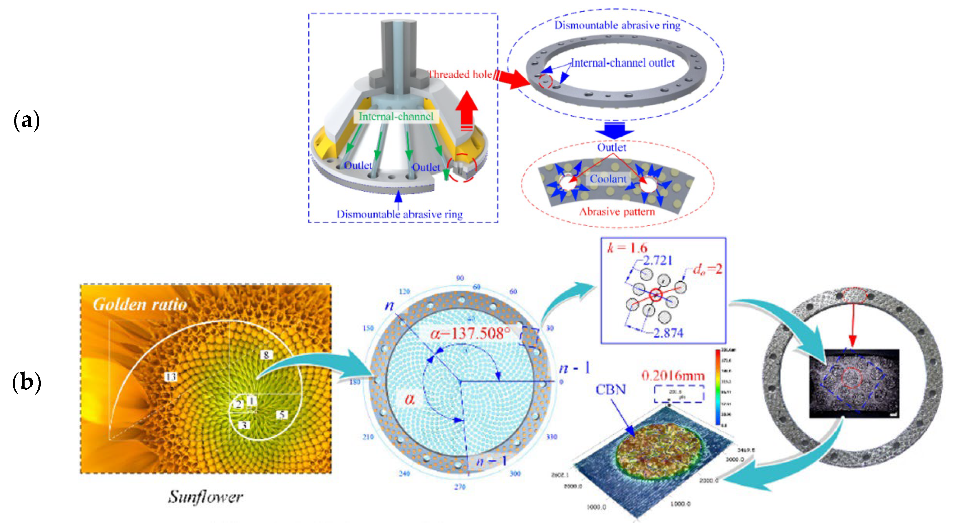
| Peng et al., (2022) [76] | A bowl-shaped grinding wheel with internal cooling and a phyllotactic abrasive pattern was designed. A CFD study optimized the grinding wheel’s interior structure. |
| Author and Year | Groove Geometry | ||
|---|---|---|---|
| Form | Grain Size (mesh) | Width (mm) | |
| Yuan et al., (2010) [54] | Phyllotactic | - | 1.7 |
| Wang et al., (2015) [55] | Rectangular | 80 | 0.98 |
| Yu et al., (2016a) [56] | Phyllotactic | - | ~0.29–0.39 |
| Yu et al., (2016b) [57] | Phyllotactic | 70/80 | ~0.87–1.21 |
| Yu et al., (2016c) [58] | Phyllotactic | 70/80 | ~0.87–1.21 |
| Zhang et al., (2017) [59] | Helical | - | 1.6–2.9 |
| Ding et al., (2017) [60] | Helical | 80/100 | 1.2 |
| Lyu et al., (2017) [61] | Phyllotactic | 70/80 | ~0.87–1.21 |
| Yu et al., (2018) [62] | Phyllotactic | - | ~0.88–1.21 |
| Zhang et al., (2018) [53] | Helical | 40/50 | 2.5 |
| Yu et al., (2019a) [63] | Phyllotactic | 40/50 | ~0.75–1.06 |
| Yu et al., (2019b) [64] | Phyllotactic | 40/50 | ~0.75–1.06 |
| Yu et al., (2019c) [65] | Phyllotactic | 40/50 | ~0.75–1.06 |
| Zhang et al., (2019a) [66] | Helical | 40/50 | 1.2–2.4 |
| Zhang et al., (2019b) [67] | Helical | 40/50 | 1.2–2.4 |
| Qiu et al., (2019) [68] | Spiral, rectangular, and circular | - | 2.0–3 |
| Zhu et al., (2019) [69] | Helical | 80/100 | 1.2 |
| Zhang et al., (2020) [70] | Rectangular | - | 1.0–3 |
| Peng et al., (2020) [71] | Helical and rectangular | 80 | 1.5 |
| Peng et al., (2021a) [72] | Helical | - | 1 |
| Peng et al., (2021b) [73] | Phyllotactic | 80 | - |
| Guo et al., (2022) [74] | Helical | - | ~0.5 |
| Wang et al., (2022) [75] | Helical | 40/45 | 1.2 |
| Peng et al., (2022) [76] | Phyllotactic | 80 | - |
| Author and Year | Summary |
|---|---|
| Guo et al., (2014) [82] | The effects of laser parameters on microstructured surfaces (focal point shift, laser power, scanning speed, and scanning passes) were explored and adjusted. |
| Deng et al., (2017) [83] | The effects of groove angle and geometry on the surface quality of the workpiece were evaluated. |
| Zhang et al., (2018) [84] | Evaluation of six different groove geometries on grinding performance and wear behavior. |
| Guo et al., (2018) [85] | The effect of microgrooves combined with microrefinement of the abrasive grains on the surface of a CVD diamond wheel and on grinding force and grind quality. |
| Zhang et al., (2019a) [86] | To produce macro–microstructured patterns on the wheel’s surface, a methodical strategy was developed and implemented. A theoretical model of grinding force was provided and experimentally validated. |
| Zhang et al., (2019b) [87] | Evaluation of five different groove geometries on grinding operations. Grinding forces were compared and the influences of workpiece speed, grinding wheel speed, and depth of cut on grinding force were discussed. |
| Wu et al., (2019) [88] | Grooves were produced on an abrasive grinding wheel to later transfer the texture to the surface of hard and brittle working materials. |
| Azarhoushang et al., (2019) [89] | Evaluation of the grinding of ceramic matrix composites with grinding wheels structured by two different methods (laser and segmented). The grinding tests were carried out at different material-removal rates and cutting speeds. The laser method was more emphasized in the paper. |
| Deng et al., (2019) [90] | In a coarse-grained diamond grinding wheel, the groove shape, structuring efficiency, and rate of structured grains were all assessed. |
| Li et al., (2020a) [91] | Grinding wheels with inclined and rectangular-cross-section grooves were compared in the grinding process. |
| Li et al., (2020b) [92] | The influence of laser beam parameters on the generation of different groove geometries was studied. |
| Wu et al., (2020) [93] | Two different microtexture geometries were ablated directly on diamond grains on an engineered grinding wheel using a pulsed laser. |
| Zhang et al., (2020) [94] | A type of biomimetic fractal-branched grinding wheel was designed based on leaf veins. Grinding tests were performed and the experimental results were compared with those for a conventional grinding wheel. |
| Zhao et al., (2020) [95] | To produce patterned CBN/CuSnTi-grinding wheels, a coaxial powder feeding laser cladding technique utilizing CAD/CAM technology was introduced. |
| Li et al., (2021) [80] | The effects of laser pass numbers and scanning speeds on groove geometry were discussed. |
| Monier et al., (2022) [96] | The ability to pattern a wheel with advanced regular and irregular pattern geometries was evaluated by computational simulation. However, only a geometry was produced and tested in grinding. |
| Hou et al., (2022) [97] | A laser scanning method was used to create grooves on grinding wheels using an ultrafast laser processing device. |
| Geng et al., (2022) [98] | For metal-bond diamond grinding wheels, a conditioning approach was designed. The same laser source was used throughout the conditioning chain, including the truing, dressing, and texturing of the grinding wheel. |
| Author and Year | Groove Geometry | |||
|---|---|---|---|---|
| Form | Angle (deg) | Depth (mm) | Width (mm) | |
| Guo et al., (2014) [82] | Helical | - | - | ~0.004–0.016 |
| Deng et al., (2017) [83] | “V” and “W” shapes | 0, 30, 60 and 90 | 0.0382 | 0.0753 |
| Zhang et al., (2018) [84] | Helical, cross linear, zigzag, and “U” shape | 0, 30, 45 and 90 | 0.85 | 1.2 |
| Guo et al., (2018) [85] | Helical | - | 0.008 | 0.004–0.006 |
| Zhang et al., (2019a) [86] | Cross linear, waves, and zig zag | 30, 45 and 90 | 0.85 | 1.2 |
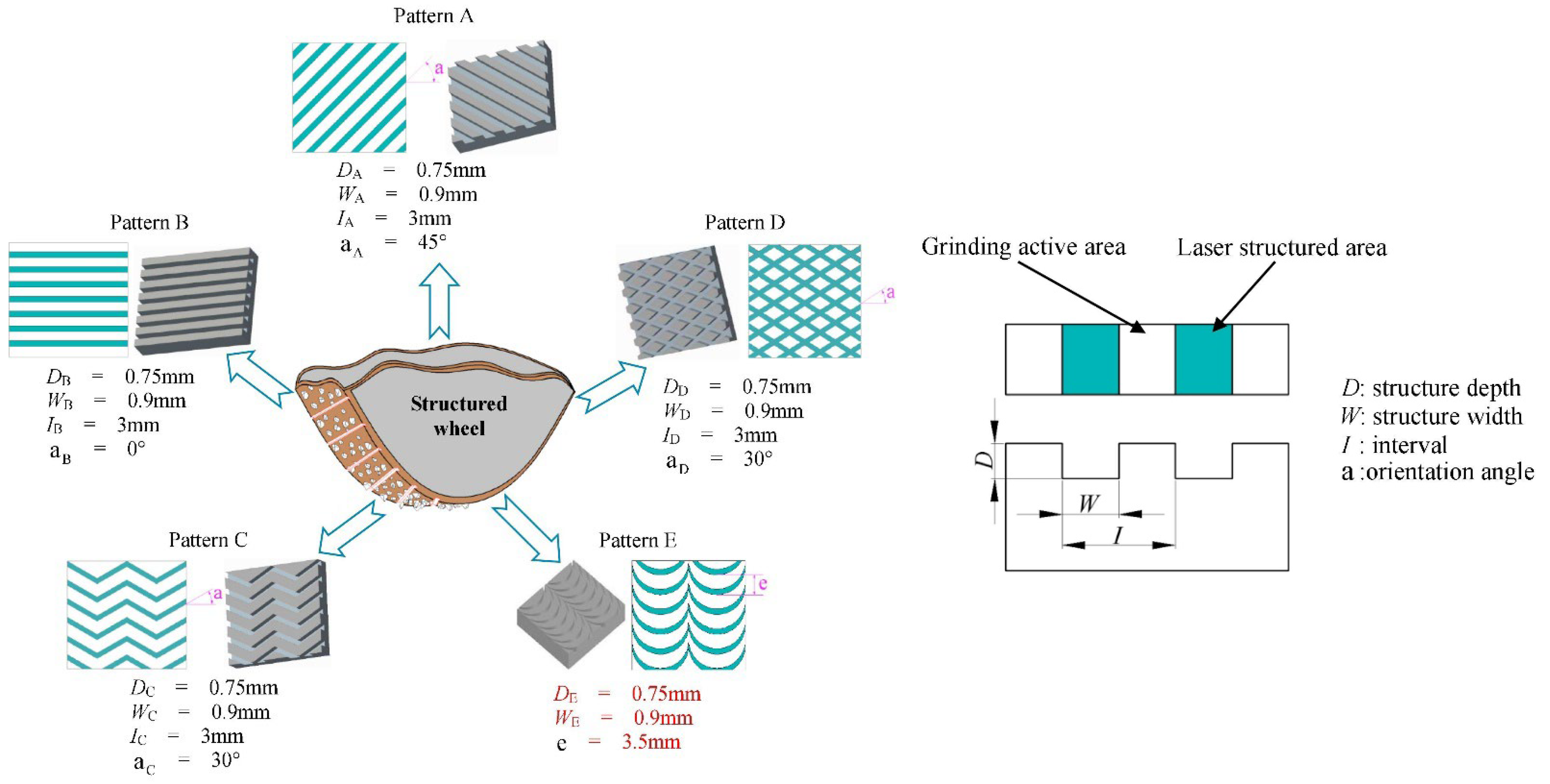
| Zhang et al., (2019b) [87] | Helical, cross linear, zigzag, and waves | 0, 30 and 45 | 0.75 | 0.9 |
| Wu et al., (2019) [88] | Helical | 4.52 | ~0.102 | ~0.187 |
| Azarhoushang et al., (2019) [89] | Slots (segmented grooves) and cross linear (laser grooves) | - | 0.35 | 0.85 |
| Deng et al., (2019) [90] | “V” and “W” shapes | - | 0.02–0.071 | 0.003–37.6 |
| Li et al., (2020a) [91] | Helical | - | 0.95 and 1 | 0.65 |
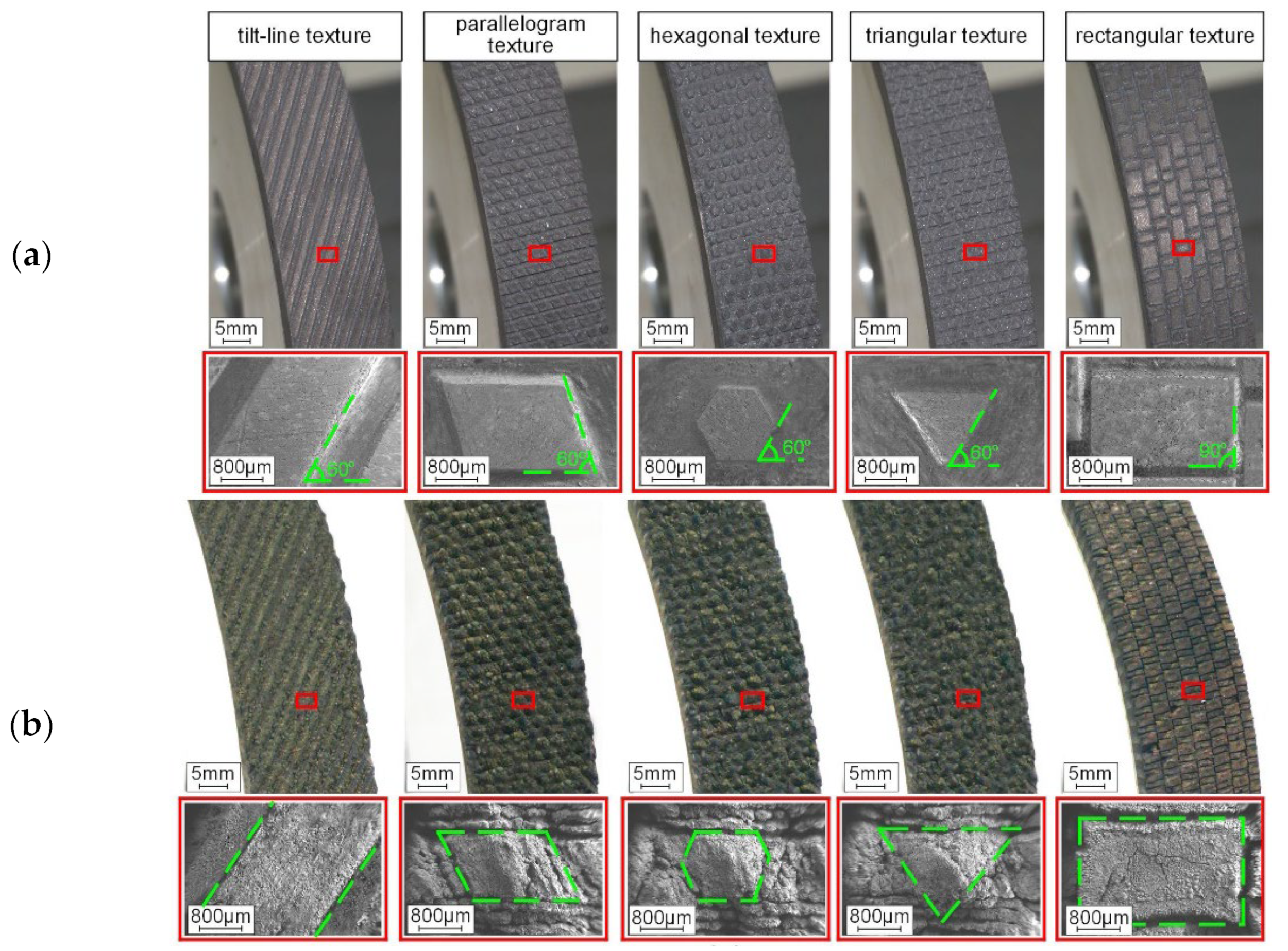
| Li et al., (2020b) [92] | Helical, parallelogram, hexagonal, triangular, and rectangular | 60 and 90 | 0.3–1 | 0.8–1.8 |
| Wu et al., (2020) [93] | Cross linear, with and without holes | - | 0.15–0.2 | 0.02–0.05 |
| Zhang et al., (2020) [94] | Leaf vein | - | 1 | 3 |
| Zhao et al., (2020) [95] | Helical, zigzag, and “U” shape | - | - | - |
| Li et al., (2021) [80] | “V” shape and hemispheres | - | 0.4–4 | ~0.18–0.3 |
| Monier et al., (2022) [96] | Slots | - | - | ~0.19–0.33 |
| Hou et al., (2022) [97] | Lines with “U” shapes | - | 1 | 1 |
| Geng et al., (2022) [98] | Helical and cross linear | - | 0.08–0.25 | 0.2–0.35 |
| Author and Year | Summary |
|---|---|
| Tian et al., (2018) [100] | In this work, a novel approach for fabricating porous, metal-bonded grinding wheels using selective laser melting (SLM) technology was developed. |
| Du et al., (2019) [101] | In this investigation, resin-bonded diamond grinding wheels with internal cooling holes were 3D-printed using selective laser sintering (SLS). |
| Wang et al., (2021) [102] | The method described by Tian et al. [100] was used to produce four wheels with different groove geometries. The focus of the work was the grinding performance that could be achieved with different grinding wheels. |
| Li et al., (2021) [103] | The method described by Tian et al. [100] was used to produce three wheels with different groove geometries. Here, the focus was on the design and modeling of the different grinding wheels. |
| Huang et al., (2021) [99] | This work describes the use of direct ink writing (DIW) to manufacture three types of vitrified grinding wheels with varied groove geometries. |
| Author and Year | Method | Groove Geometry | |
|---|---|---|---|
| Form | Width (mm) | ||
| Tian et al., (2018) [100] | SLM | Honeycomb and octahedron structure | - |
| Du et al., (2019) [101] | SLS | Holes | 1.5 and 2.5 |
| Wang et al., (2021) [102] | SLM | Octahedron, Schwarz P, Schwarz D, and Schoen I-WP structures | - |
| Li et al., (2021) [103] | SLM | Schwarz P, Schwarz D, and Schoen I-WP structures | - |
| Huang et al., (2021) [99] | DIW | Triangle and lattice | 4 and 6 |
| Author and Year | Summary |
|---|---|
| Tawakoli et al., (2011a) [105] | A segmented grinding wheel was designed, fabricated, and tested. The conventional grinding process was compared with the intermittent grinding process. |
| Tawakoli et al., (2011b) [104] | Study of the feasibility of intermittent grinding with a segmented wheel using two ceramic matrix composite (CMC) materials. |
| Azarhoushang et al., (2014) [106] | Study of the wear of non-segmented and segmented diamond wheels in high-speed deep grinding of carbon-fiber-reinforced ceramics. |
| Author and Year | Summary |
|---|---|
| Li et al., (2018) [109] | This research presented a method for designing groove shapes based on the intended operating temperature. |
| Zhang et al., (2019) [110] | This study aimed to estimate the essential profile characteristics, including groove depth and groove breadth, of the grooves on AWJ-textured metal-bonded grinding wheels. |
| Zhang et al., (2021) [111] | The mechanisms behind the AWJ truing process and the integrated rough–fine grinding process were studied to guide the development of the technology. |
| Author and Year | Groove Geometry | |||
|---|---|---|---|---|
| Form | Angle (deg) | Width (mm) | Depth (mm) | |
| Li et al., (2018) [109] | Helical, zigzag, and “V” shape | 31.4, 50.5, and 180 | 1.74 and 1.91 | - |
| Zhang et al., (2019) [110] | Helical | 90 | ~0.9–1.1 | 0.6–1 |
| Zhang et al., (2021) [111] | Helical | 90 | 1.6 | 0.5 |
Publisher’s Note: MDPI stays neutral with regard to jurisdictional claims in published maps and institutional affiliations. |
© 2022 by the authors. Licensee MDPI, Basel, Switzerland. This article is an open access article distributed under the terms and conditions of the Creative Commons Attribution (CC BY) license (https://creativecommons.org/licenses/by/4.0/).
Share and Cite
Costa, S.; Pereira, M.; Ribeiro, J.; Soares, D. Texturing Methods of Abrasive Grinding Wheels: A Systematic Review. Materials 2022, 15, 8044. https://doi.org/10.3390/ma15228044
Costa S, Pereira M, Ribeiro J, Soares D. Texturing Methods of Abrasive Grinding Wheels: A Systematic Review. Materials. 2022; 15(22):8044. https://doi.org/10.3390/ma15228044
Chicago/Turabian StyleCosta, Sharlane, Mário Pereira, João Ribeiro, and Delfim Soares. 2022. "Texturing Methods of Abrasive Grinding Wheels: A Systematic Review" Materials 15, no. 22: 8044. https://doi.org/10.3390/ma15228044
APA StyleCosta, S., Pereira, M., Ribeiro, J., & Soares, D. (2022). Texturing Methods of Abrasive Grinding Wheels: A Systematic Review. Materials, 15(22), 8044. https://doi.org/10.3390/ma15228044