Article

Analysis of Acousto-Optic Figure of Merit in KGW and KYW Crystals

by
Konstantin B. Yushkov
*,
Natalya F. Naumenko
and
Vladimir Ya. Molchanov
Acousto-Optical Research Center, University of Science and Technology MISIS, 119049 Moscow, Russia
*
Author to whom correspondence should be addressed.
Materials 2022, 15(22), 8183; https://doi.org/10.3390/ma15228183
Submission received: 25 October 2022 / Revised: 15 November 2022 / Accepted: 15 November 2022 / Published: 17 November 2022
(This article belongs to the Special Issue Acousto-Optical Spectral Technologies)

Abstract

:
Monoclinic potassium rare-earth crystals are known as efficient materials for solid-state lasers and acousto-optic modulators. A number of specific configurations for acousto-optic devices based on those crystals have recently been proposed, but the acousto-optic effect of those crystals has only been analyzed fragmentarily for some interaction directions. In this work, we numerically searched for the global maxima of an acousto-optic figure of merit for isotropic diffraction in KGd(WO4)2 and KY(WO4)2 crystals. It was demonstrated that the global maxima of the acousto-optic figure of merit in those crystals occur in the slow optical mode propagating along the crystal’s twofold symmetry axis and in the acoustic wave propagating orthogonally, both for quasi-longitudinal and quasi-shear acoustic modes. The proposed calculation method can be readily used for the optimization of the acousto-optic interaction geometry in crystals with arbitrary symmetry.

1. Introduction

In the recent decade, there has been a growth of interest in the acousto-optic (AO) properties of biaxial crystals [1,2,3,4,5,6,7,8,9,10,11,12,13,14,15,16,17,18,19,20,21,22,23,24]. The main factors motivating the research in this area are (1) the good optical and acousto-optic properties of some biaxial crystals used in nonlinear optics and laser physics, and (2) a larger number of material constants in biaxial crystals as compared to uniaxial ones, which provides more useful configurations of AO interactions. Moreover, biaxial crystals are of special interest in AO research since they can provide unique configurations of the Bragg diffraction for laser beam deflection and spatial filtering [11,19,24].
In particular, potassium rare-earth tungstate crystals, also known as the KREW family, have recently been recognized as efficient crystal materials for applications in acousto-optics [2,3,4]. Those crystals belong to the monoclinic crystal system, which ensures a large number of independent elastic and photoelastic constants. Potassium gadolinium tungstate (KGW), KGd(WO 4 ) 2 , and potassium yttrium tungstate (KYW), KY(WO 4 ) 2 , are the most prominent crystals of the KREW family. Previous studies included measurements and computations of the AO figure of merit M 2 only for certain geometries of an AO interaction, with light propagating near the twofold symmetry axis of the crystal and ultrasound propagating on the symmetry plane [3,4,7,14,22]. A fair AO figure of merit in KREW crystals has been combined with a high laser-induced damage threshold [23,25]. This allowed for the design and fabrication of several experimental configurations of AO modulators (AOMs) and Q-switches for infrared (IR)-pulsed lasers [14,15,17,23]. Specific combinations of the acoustic and photoelastic properties of those crystals has prompted the creation of novel designs for AO devices, including spatial light modulators [18] as well as two-coordinate monolithic deflectors and polarization switches [22].
In this work, we explore the spatial distributions of an AO figure of merit M 2 in monoclinic KREW crystals with an arbitrary orientation of light and ultrasound under the assumption of a small-angle orthogonal diffraction. A procedure that can be used to search for the global maxima of the M 2 for isotropic AO diffraction in crystals with arbitrary symmetry is proposed and validated. Numerical results for KGW and KYW crystals are obtained and analyzed.

2. Materials and Methods

2.1. KREW Crystals’ Physical Properties

KYW and KGW are monoclinic crystals of the 2/m point group. The orientation of the dielectric axes relative to the crystal’s unit cell is shown in Figure 1. We use the axes setting for monoclinic crystals, with the Z axis being parallel to the twofold symmetry axis of the crystal ( b crystallographic axis and N p dielectric axis); X and Y are the dielectric axes N m and N g , respectively.
The acoustic and photoelastic constants of KREW crystals have been measured by Mazur et al. [2,6]. The stiffness and photoelastic tensors, c i j k l and p i j k l , are written in Voight’s notation. In monoclinic crystals, there are 13 independent stiffness coefficients c q r :
c q r = c 11 c 12 c 13 0 0 c 16 c 12 c 22 c 23 0 0 c 26 c 13 c 23 c 33 0 0 c 36 0 0 0 c 44 c 45 0 0 0 0 c 45 c 55 0 c 16 c 26 c 36 0 0 c 66
and 20 independent photoelastic coefficients p q r :
p q r = p 11 p 12 p 13 0 0 p 16 p 21 p 22 p 23 0 0 p 26 p 31 p 31 p 33 0 0 p 36 0 0 0 p 44 p 45 0 0 0 0 p 54 p 55 0 p 61 p 62 p 63 0 0 p 66 .
The values of the stiffness, photoelastic, and dielectric constants for the KGW crystal are listed in Appendix A.1, and those for the KYW crystal are in Appendix A.2.

2.2. Acousto-Optic Figure of Merit

The efficiency of the AO interaction in crystals depends on both acoustic and optical wave propagation directions with respect to the crystal axes. Any direction of the acoustic wave vector s is associated with three bulk acoustic wave (BAW) eigenmodes having orthogonal polarization vectors u and different phase velocities v. The exceptions are the acoustic axes, i.e., the directions corresponding to the degeneracy of two acoustic modes [21]. Any propagation direction of light m in a birefringent crystal is associated with two orthogonal eigenmodes that have polarization vectors d and refractive indices n. There are two types of AO diffraction: isotropic diffraction, which corresponds to the same polarization of incident and diffracted beams, and anisotropic diffraction, which corresponds to the orthogonal polarization of the beams.
Furthermore, we assume the isotropic diffraction type and remain within a small-angle approximation, i.e., that the optical wave normal vector m and the polarization vector d are the same for incident and diffracted waves. This approximation is valid for most of the configurations of isotropic diffraction, except for those where light propagates near the optic axis of a biaxial crystal. In the neighborhood of conical optic axes, the polarizations of eigenwaves d rapidly change with the wave normal direction m , and isotropic diffraction may be mixed with the anisotropic one [24]. In the other cases, i.e., those far from singular points of the refractive index surface and those in the typical range of ultrasound frequencies of the Bragg diffraction—from a few tens to a few hundred MHz—the double Bragg angle is on the order of 1 ° , and the difference between polarization vectors d in the directions of incident and diffracted light is small. Thus, the small-angle approximation allows one to eliminate the ultrasound frequency from the problem parameters. In addition, the error of the experimental measurement of the photoelastic constants is more than 10% [6], therefore the error of M 2 p eff 2 can be estimated to be at 20 %.
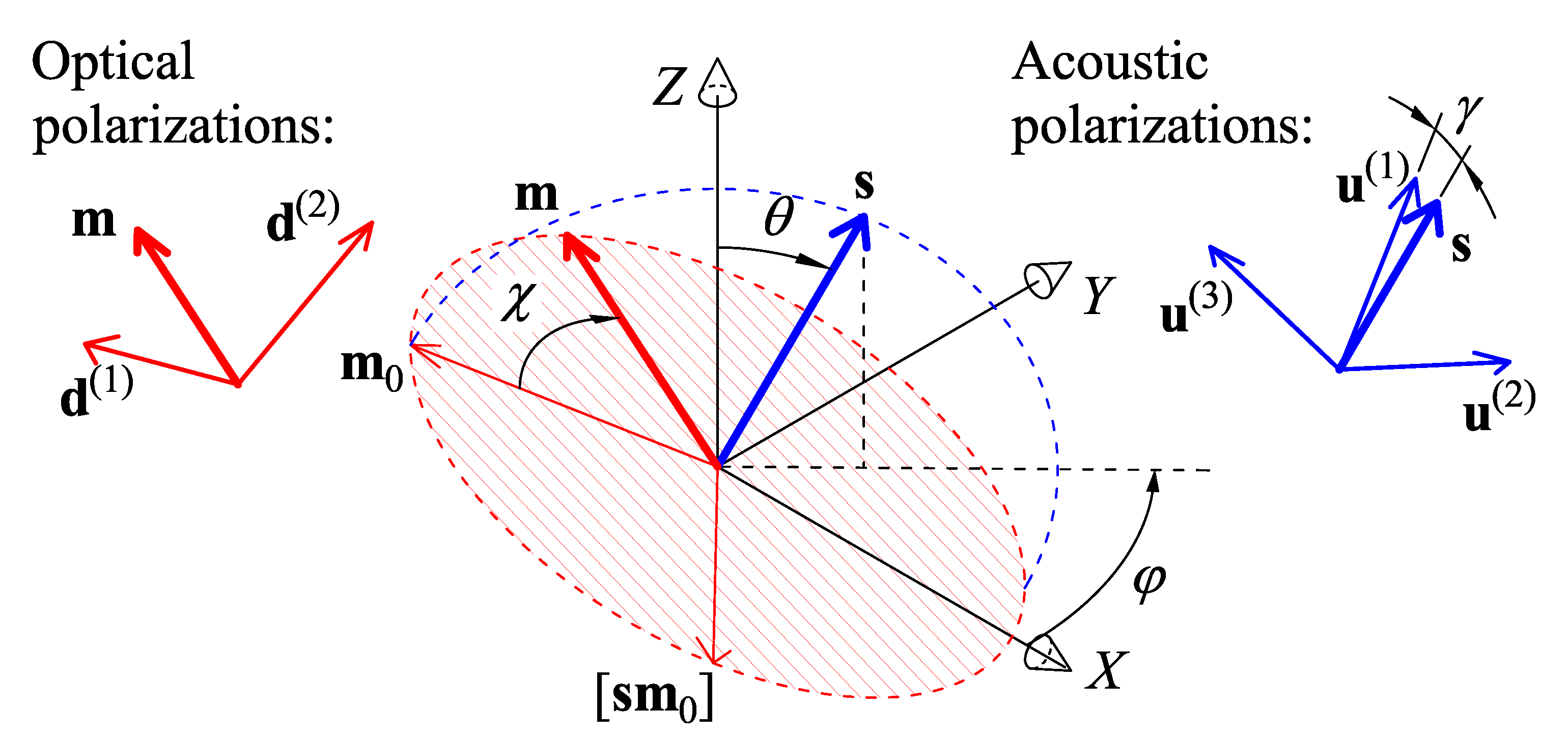
Figure 2 illustrates the orientation of the acoustic and optical wave vectors and polarizations. Standard procedures for calculating the optical and acoustic eigenmodes in crystals are described elsewhere [26,27]. Hereinafter, we sort the acoustic and optical modes of crystals from the fastest to the slowest, i.e., v ( 1 ) > v ( 2 ) v ( 3 ) and n ( 1 ) n ( 2 ) . The fastest acoustic mode u ( 1 ) is a quasi-longitudinal (QL) wave, and the other modes, u ( 2 ) and u ( 3 ) , are quasi-shear (QS) waves. The polarization angle of acoustic waves is defined as γ = ( s , u ( 1 ) ) .
The direction of the acoustic wave vector is a function of two Euler angles, φ [ 0 , 360 ° ] and θ [ 0 , 90 ° ] , and is relative to the axes Z and X:
s ( φ , θ ) = { sin θ cos φ , sin θ sin φ , cos θ } .
Small-angle approximation is equivalent to orthogonal diffraction geometry, ( m s ) = 0 , so one can use the parametrization of m as follows:
m ( s , χ ) = m 0 cos χ + [ m 0 s ] sin χ ,
where the initial direction m 0 is orthogonal to the line of nodes:
m 0 ( φ , θ ) = { cos θ cos φ , cos θ sin φ , sin θ } .
For a certain interaction geometry, the effective photoelastic constant is expressed as follows [28]:
p eff ( α , β ) ( s , m ) = d i ( β ) d j ( β ) p i j k l s k u l ( α )
where α = 1 , 2 , 3 is the acoustic mode number, β = 1 , 2 is the optical mode number, and summation over repeated lower indices is assumed. In Equation (7), d i and d j are the components of the optical polarization eigenvector d ( β ) ( m ) corresponding to the β -th optical mode, and u ( s ) is the acoustic displacement vector corresponding to the α -th acoustic mode.
M 2 ( α , β ) ( s , m ) = n ( β ) 6 p eff ( α , β ) 2 ρ v ( α ) 3
Numerical maximum search was used to find the optimal propagation of the optical beam that maximizes M 2 for a given BAW propagation direction. The result of this search is the optical direction, expressed through angle χ :
χ max ( α , β ) ( s ) = arg max χ [ 0 , 360 ° ] M 2 ( α , β ) ( s , m ( s , χ ) )
The final result is the maximum figure of merit for a chosen acoustic direction s and combination of modes ( α , β ) .
M 2 max ( α , β ) ( φ , θ ) = M 2 ( α , β ) ( s , m ( s , χ max ( α , β ) ) )
In total, there are 6 combinations of optical and acoustic modes. Each combination was processed independently.

2.3. Software

The original software for computing M 2 max was developed in the Fortran programming language. The initial data are the set of material constants (dielectric permittivity tensor ε i i , stiffness c p q and photoelastic p q r matrices) defined in the crystals’ dielectric axes. The software is based on numerical techniques of linear algebra instead of analytical solutions. Therefore, it is universal and can be applied to crystals of any symmetry.
Standard methods for calculating the optical and acoustic eigenmodes in crystals were used for every acoustic wave normal vector s and optical wave normal vector m [26,27]. Then, Equations (6)–(9) were used for each possible pair of mode indices α and β . In the computations, the grid steps were 2 ° for φ and 1 ° for θ and χ .

3. Results

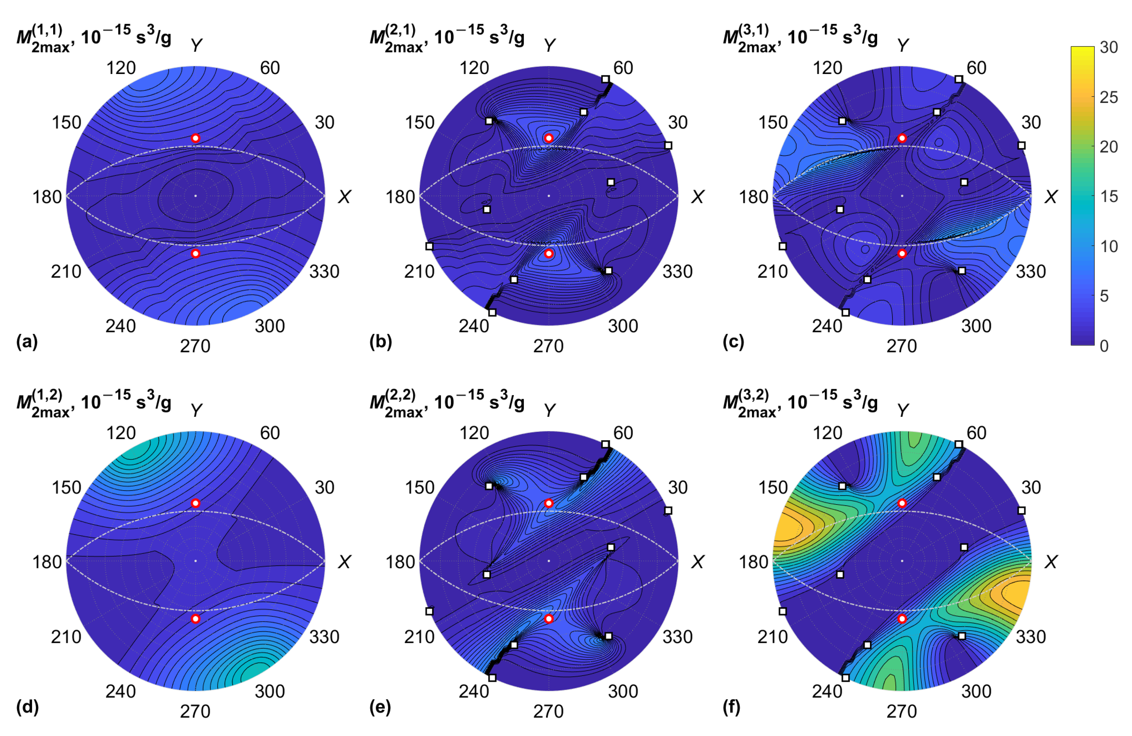
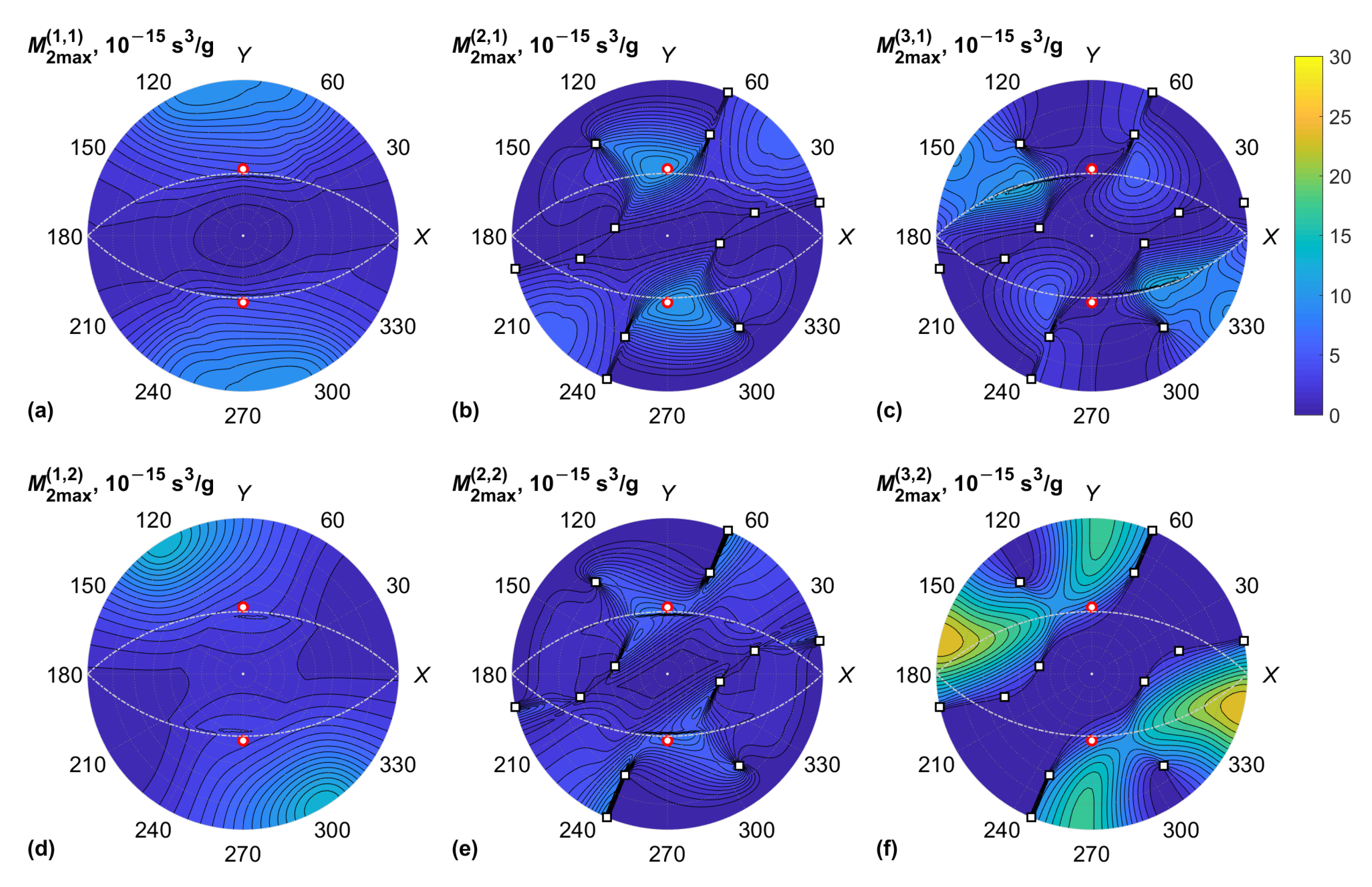
The results of the numerical simulations for KGW and KYW are M 2 max ( α , β ) and χ max ( α , β ) , as functions of the Euler angles φ and θ for three BAW modes ( α = 1 , 2 , 3 ) and two optical modes ( β = 1 , 2 ) of the crystals. Full numerical data on χ max and M 2 max can be found in the related dataset in [29]. All diagrams are plotted in stereographic projection showing the upper hemisphere, θ [ 0 , 90 ° ] .
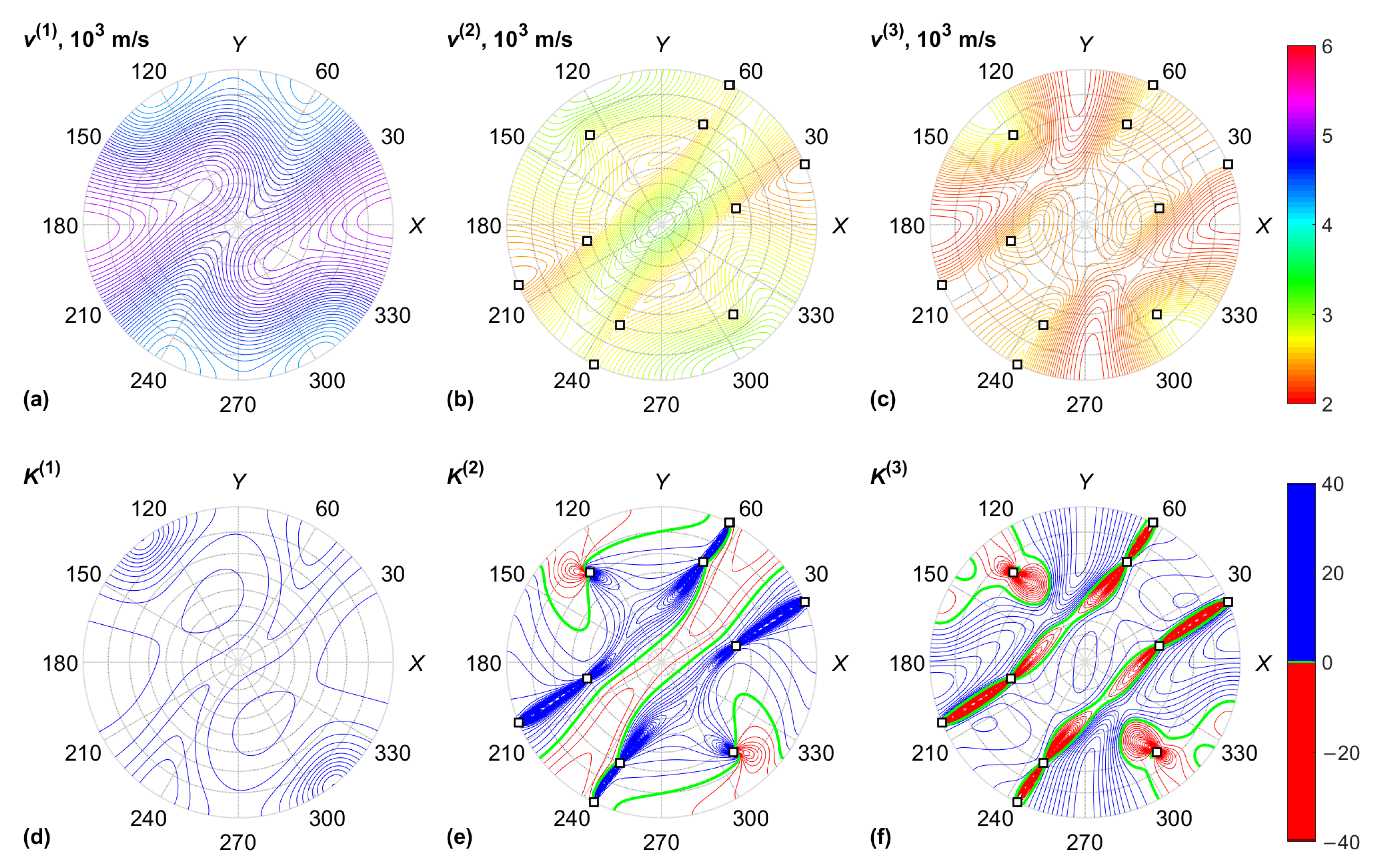
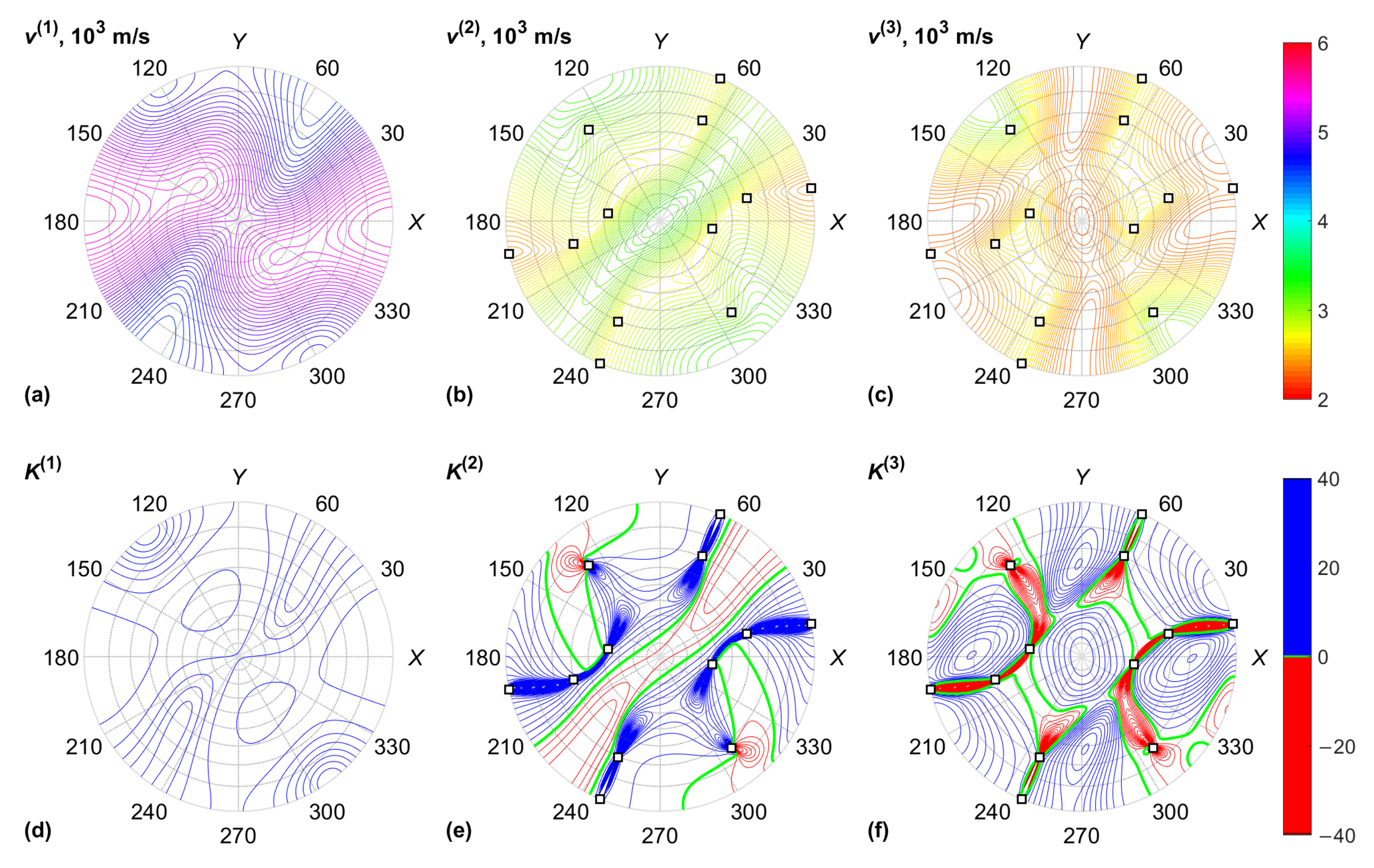
The data for the KGW crystal are plotted in Figure 3 and Figure 4, including the acoustic properties of the crystal: BAW velocities v ( α ) and normalized Gaussian curvatures K ( α ) of the slowness surfaces. The Gaussian curvature is the product of two dimensionless BAW diffraction coefficients, which characterize the anisotropy of acoustic beam diffraction in crystals [30]. This coefficient tends to infinity in the neighborhood of conical acoustic axes. Similar results for the KYW crystal are plotted in Figure 5 and Figure 6.
Table 1 summarizes diffraction geometry parameters that maximize the AO figure of merit M 2 in KGW and KYW crystals. The table includes the direction angles φ and θ of the BAW, the optical rotation angle χ that defines the diffraction plane, and polarizations of the interacting beams. The data for the QS modes include the global maxima over both QS modes.
General features of M 2 data presented in Figure 4 and Figure 6 are the following: Firstly, the maxima of the figure of merit are associated with the minima of BAW velocity since M 2 v 3 . Secondly, rapid changes in M 2 for the QS BAW modes took place near the acoustic axes of the crystal and the directions of high acoustic anisotropy between them. The reason for this is the fast rotation of BAW polarization vectors u ( 2 ) and u ( 3 ) near the directions of high anisotropy [30]. Rapid changes in M 2 max were also observed for some BAW directions orthogonal to the optic axes of the crystal since the optical wave normal vector m in this case crossed the optic axis associated with polarization singularity. However, we note that the small-angle approximation has a limited validity when light propagates near an optic axis because of the high optical anisotropy and singularity of the polarization field affecting the AO phase matching [24]. For this reason, the AO diffraction of light propagating near the optic axis of a biaxial crystal cannot be used for the design of AO modulators. On the other hand, it enables the design of unique types of AO devices for the deflection of light and processing vector beams [1,5,11,19]. In this case, the AO figure of merit should be calculated with respect to the actual frequency of ultrasound and the polarizations of optical eigenmodes.

4. Discussion

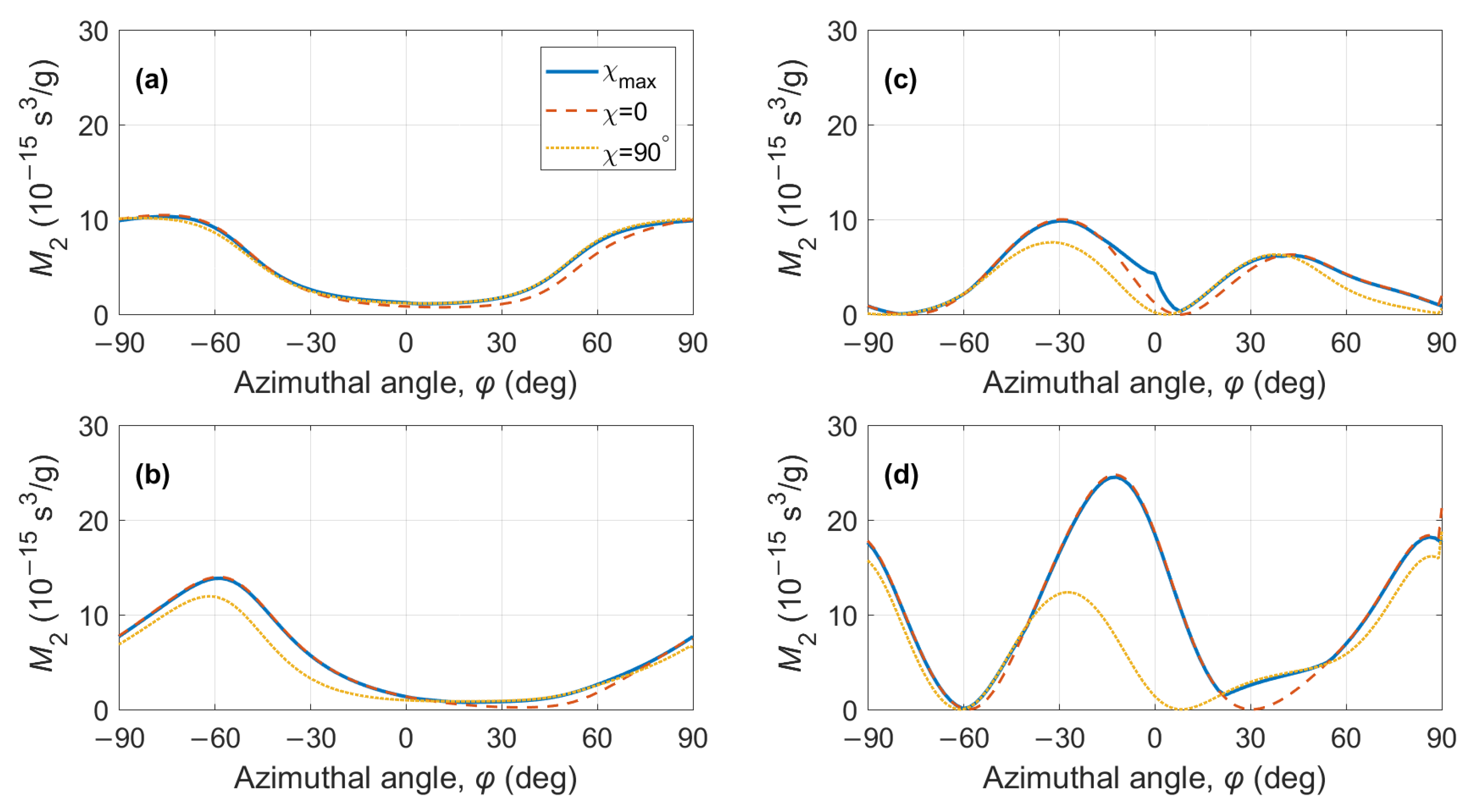
According to the plots in Figure 4 and Figure 6, the global maxima of the figure of merit M 2 occurred for the QS BAW mode propagating on the X Y plane and which has a displacement orthogonal to the Z axis. The peaks of M 2 were higher for the slow optical mode ( β = 2 ). The global maxima were achieved at χ = 0 , which corresponds to the optical wave normal vector m parallel to the Z axis. To prove this, we selected the BAW propagation in the X Y plane, i.e., θ = 90 ° , and φ is a variable; we then calculated the figure of merit M 2 ( χ ) analytically.
Analytical expressions for p eff can be readily derived for the case of χ = 0 , i.e., an optical wave propagating along the Z axis [22]:
p ql ( i ) = p i 1 cos φ cos ( φ + γ ) + p i 2 sin φ sin ( φ + γ ) + p i 6 sin ( 2 φ + γ ) ;
p qs ( i ) = p i 1 cos φ sin ( φ + γ ) + p i 2 sin φ cos ( φ + γ ) + p i 6 cos ( 2 φ + γ ) ,
where i = 1 for the fast optical mode with the polarization vector d ( 1 ) = { 1 , 0 , 0 } , and i = 2 for the slow optical mode with d ( 2 ) = { 0 , 1 , 0 } . Equations (10) and (11) describe the interaction geometry with the optical beam propagating along the Z axis, i.e., at χ = 0 . These equations are also valid at i = 3 for the fast optical mode propagating orthogonally to s on the X Y plane, i.e., at χ = ± 90 ° . This mode has a polarization vector of d ( 1 ) = { 0 , 0 , 1 } . The slow optical mode for this direction has a polarization of d ( 2 ) = { cos φ , sin φ , 0 } and the following effective photoelastic constants:
p ql χ = 90 ° = p ql ( 1 ) cos 2 φ + p ql ( 2 ) sin 2 φ + p ql ( 6 ) sin 2 φ ;
p qs χ = 90 ° = p qs ( 1 ) cos 2 φ + p qs ( 2 ) sin 2 φ + p qs ( 6 ) sin 2 φ .
To the best of our knowledge, the p 61 , p 62 , p 63 , and p 66 constants have not yet been measured [6], and in all simulations, they were used with zero values.
The maximum values M 2 max are compared with the calculated data in Figure 7 and Figure 8. In panels (a) and (b), the maximum figure of merit was found for the QL BAW mode and compared to the calculations in Equations (10) and (12). In panels (c) and (g), the maximum figure of merit was found for both QS BAW modes, the fast and the slow, and then compared to the calculations from Equations (11) and (13).

5. Conclusions

We have reported a procedure that can be used to search for the global maxima of the AO figure of merit in crystals of lower symmetry classes. The procedure was able to find the optimal propagation direction of light and the corresponding figure of merit as the functions of the BAW propagation direction in crystals. We demonstrated this procedure with the use of two monoclinic crystals, KGW and KYW, which have previously shown high AO efficiency in certain configurations of AO interaction in the near-IR spectral region.
Our numerical simulations demonstrated that the global maxima of the figure of merit M 2 for isotropic diffraction in KGW and KYW crystals can be obtained for the BAW propagation on the X Y plane and the optical propagation along the Z crystal axis. This conclusion is valid both for QL and QS BAW modes, and the highest M 2 values are produced for the slow optical mode polarized along the Y (i.e., N g ) dielectric axis. Nevertheless, we note that numerical data on M 2 in KREW crystals should be refined in the future since 8 out of the 20 photoelastic constants of these crystals have not been measured to date.

Author Contributions

Conceptualization, K.B.Y. and V.Y.M.; methodology, K.B.Y.; software, N.F.N.; investigation, K.B.Y. and N.F.N.; data curation, K.B.Y.; writing—original draft preparation, K.B.Y.; writing—review and editing, N.F.N. and V.Y.M.; project administration, V.Y.M. All authors have read and agreed to the published version of the manuscript.

Funding

This research was funded by the Ministry of Science and Higher Education of the Russian Federation (Priority2030) and the University of Science and Technology MISIS (K7-2022-052).

Institutional Review Board Statement

Not applicable.

Informed Consent Statement

Not applicable.

Data Availability Statement

The data presented in this study are openly available on Mendeley Data at http://dx.doi.org/10.17632/cg38s35c8d.1, accessed on 24 October 2022.

Conflicts of Interest

The authors declare no conflict of interest.

Abbreviations

The following abbreviations are used in this manuscript:
AOAcousto-optic
BAWBulk acoustic wave
IRInfrared
KGWKGd(WO 4 ) 2 , potassium gadolinium tungstate
KREWPotassium rare-earth tungstate
KYWKY(WO 4 ) 2 , potassium yttrium tungstate
QLQuasi-longitudinal
QSQuasi-shear

Appendix A

Appendix A.1

Material constants of the KGW crystal relevant to this research are the following: The crystal density is ρ = 7.270 g/cm 3 . The elastic constants of the KYW crystal are as follows [2]:
c q r = 197.8 51.1 92.5 0 0 3.7 140.0 61.3 0 0 0.9 171.7 0 0 3.0 64.0 12.1 0 45.2 0 31.4 · GPa
The lower sub-diagonal part of the matrix is not shown because of its symmetry. The photoelastic tensor of the KGW crystal is the following [6]:
p q r = 0.11 0.23 0.14 0 0 0.053 0.13 0.28 0.09 0 0 0.13 0.13 0.23 0.04 0 0 0.025 0 0 0 p 44 p 45 0 0 0 0 p 54 p 55 0 p 61 p 62 p 63 0 0 p 66
Eight coefficients in the lower half of the matrix are not known. The optical properties of KGW are described with single-term, IR-corrected Sellmeier’s equations [31]:
ε 11 = n m 2 = 0.8753 + 3.0976 λ 2 / ( λ 2 0.1554 2 ) 0.00042 λ 2 ; ε 22 = n g 2 = 1.5157 + 2.6141 λ 2 / ( λ 2 0.1733 2 ) + 0.00183 λ 2 ; ε 33 = n p 2 = 0.9927 + 2.8661 λ 2 / ( λ 2 0.1523 2 ) 0.00139 λ 2 ,
which correspond to the following refractive indices at λ = 1.06   μ m: n p = ε 33 = 1.979 , n m = ε 11 = 2.010 , and n g = ε 22 = 2.050 . The angle between the dielectric axis Y and the crystallographic axis c is δ = 21.5 ° . This angle was not explicitly used in the calculations, but it is necessary for recalculating the stiffness and photoelastic constants in different frames of reference.

Appendix A.2

Material constants of the KYW crystal relevant to this research are the following: The crystal density is ρ = 6.565 g/cm 3 . The elastic constants of the KYW crystal are the following [2]:
c q r = 202.2 51.0 90.9 0 0 3.3 150.6 60.9 0 0 2.7 176.8 0 0 6.2 61.9 15.4 0 41.8 0 33.5 · GPa
The photoelastic tensor of the KYW crystal is as follows [6]:
p q r = 0.12 0.33 0.17 0 0 0.04 0.14 0.27 0.10 0 0 0.14 0.15 0.35 0.05 0 0 0.02 0 0 0 p 44 p 45 0 0 0 0 p 54 p 55 0 p 61 p 62 p 63 0 0 p 66
Eight coefficients in the lower half of the matrix are not known, similar to thet KGW crystal. The optical properties of KYW are described with single-term, IR-corrected Sellmeier’s equations [31]:
ε 11 = n m 2 = 2.5253 + 1.4638 λ 2 / ( λ 2 0.2083 2 ) 0.00237 λ 2 ; ε 22 = n g 2 = 2.3951 + 1.7564 λ 2 / ( λ 2 0.2025 2 ) 0.00226 λ 2 ; ε 33 = n p 2 = 2.6986 + 1.1578 λ 2 / ( λ 2 0.2127 2 ) 0.00215 λ 2 ,
which correspond to the following refractive indices at λ = 1.06   μ m: n p = ε 33 = 1.975 , n m = ε 11 = 2.011 , and n g = ε 22 = 2.053 . The angle between the dielectric axis Y and the crystallographic axis c is δ = 17.5 ° .

References

  1. Belyi, V.N.; Khilo, N.A.; Kurilkina, S.N.; Kazak, N.S. Spin-to-orbital angular momentum conversion for Bessel beams propagating along the optical axes of homogeneous uniaxial and biaxial crystals. J. Opt. 2013, 15, 044018. [Google Scholar] [CrossRef]
  2. Mazur, M.M.; Velikovskiy, D.Y.; Mazur, L.I.; Pavluk, A.A.; Pozhar, V.E.; Pustovoit, V.I. Elastic and photo-elastic characteristics of laser crystals potassium rare-earth tungstates KRE(WO4)2, where RE = Y, Yb, Gd and Lu. Ultrasonics 2014, 54, 1311–1317. [Google Scholar] [CrossRef]
  3. Mazur, M.M.; Mazur, L.I.; Pozhar, V.E. Optimum configuration for acousto-optical modulator made of KGW. Phys. Proc. 2015, 70, 741–744. [Google Scholar] [CrossRef] [Green Version]
  4. Mazur, M.M.; Mazur, L.I.; Pozhar, V.E. Optimal configuration of an acoustooptic modulator based on a KY(WO4)(2) crystal. Tech. Phys. Lett. 2015, 41, 249–251. [Google Scholar] [CrossRef]
  5. Belyi, V.N.; Kulak, G.V.; Krokh, G.V.; Shakin, O.V. Collinear acousto-optical transformation of Bessel light beams in biaxial gyrotropic crystals. J. Appl. Spectrosc. 2016, 83, 283–287. [Google Scholar] [CrossRef]
  6. Mazur, M.M.; Mazur, L.I.; Pozhar, V.E. Specific directions of ultrasound propagation in double potassium tungstates for light modulation. Ultrasonics 2017, 73, 231–235. [Google Scholar] [CrossRef] [PubMed]
  7. Mazur, M.M.; Mazur, L.I.; Pozhar, V.E.; Shorin, V.N.; Konstantinov, Y.P. Acousto-optic modulators based on a KYW crystal. Quantum Electron. 2017, 47, 661–664. [Google Scholar] [CrossRef]
  8. Martynyuk-Lototska, I.; Trach, I.; Kokhan, O.; Vlokh, R. Efficient acousto-optic crystal, TlInS2: Acoustic and elastic anisotropy. Appl. Opt. 2017, 56, 3179–3184. [Google Scholar] [CrossRef]
  9. Wu, Q.; Gao, Z.; Tian, X.; Su, X.; Li, G.; Sun, Y.; Xia, S.; He, J.; Tao, X. Biaxial crystal β-BaTeMo2O9: Theoretical analysis and the feasibility as high-efficiency acousto-optic Q-switch. Opt. Express 2017, 25, 24893–24900. [Google Scholar] [CrossRef]
  10. Mytsyk, B.; Kryvyy, T.; Demyanyshyn, N.; Mys, O.; Martynyuk-Lototska, I.; Kokhan, O.; Vlokh, R. Piezo-, elasto- and acousto-optic properties of Tl3AsS4 crystals. Appl. Opt. 2018, 57, 3796–3801. [Google Scholar] [CrossRef]
  11. Milkov, M.G.; Voloshinov, V.B.; Isaenko, L.I.; Vedenyapin, V.N. An experimental study of ultra-wide-band and ultra-wide-aperture non-collinear acousto-optic diffraction in an optically biaxial potassium arsenate titanyl crystal. Moscow Univ. Phys. Bull. 2018, 72, 83–88. [Google Scholar] [CrossRef]
  12. Kupreychik, M.I.; Balakshy, V.I. Peculiarities of acousto-optic interaction in biaxial crystal of alpha-iodic acid. Appl. Opt. 2018, 57, 5549–5555. [Google Scholar] [CrossRef] [PubMed]
  13. Kupreychik, M.I.; Balakshy, V.I. Investigation of close to collinear anisotropic acousto-optic interaction in a biaxial crystal of alpha-iodic acid. In Proceedings of the Fourteenth School on Acousto-Optics and Applications; Grulkowski, I., Linde, B.B.J., Duocastella, M., Eds.; SPIE: Bellingham, WA, USA, 2019; Volume 11210, p. 112100O. [Google Scholar] [CrossRef]
  14. Yushkov, K.B.; Chizhikov, A.I.; Naumenko, N.F.; Molchanov, V.Y.; Pavlyuk, A.A.; Makarevskaya, E.V.; Zakharov, N.G. KYW crystal as a new material for acousto-optical Q-switches. In Proceedings of the Components and Packaging for Laser Systems V; Glebov, A.L., Leisher, P.O., Eds.; SPIE: Bellingham, WA, USA, 2019; Volume 10899, p. 1089913. [Google Scholar] [CrossRef]
  15. Pushkin, A.V.; Mazur, M.M.; Sirotkin, A.A.; Firsov, V.V.; Potemkin, F.V. Powerful 3-μm lasers acousto-optically Q-switched with KYW and KGW crystals. Opt. Lett. 2019, 44, 4837–4840. [Google Scholar] [CrossRef] [PubMed]
  16. Porokhovnichenko, D.L.; Dyakonov, E.A.; Kuznetsov, S.V.; Voronov, V.V.; Fedorov, P.P.; Zaramenskikh, K.S.; Gasanov, A.A.; Zhukova, L.V.; Korsakov, A.S.; Salimgareev, D.D. Indium iodide single crystal: Breakthrough material for infrared acousto-optics. Opt. Lett. 2020, 45, 3435–3438. [Google Scholar] [CrossRef] [PubMed]
  17. Mazur, M.M.; Mazur, L.I.; Sirotkin, A.A.; Ryabinin, A.V.; Shorin, V.N. Acousto-optic modulators of high-power laser radiation on the basis of KGW and KYW crystals. Quantum Electron. 2020, 50, 957–961. [Google Scholar] [CrossRef]
  18. Chizhikov, A.I.; Molchanov, V.Y.; Naumenko, N.F.; Yushkov, K.B. Acousto-optic spatial light modulator (SLM) based on KYW crystal. In Proceedings of the Laser Beam Shaping XX; Dudley, A., Laskin, A.V., Eds.; SPIE: Bellingham, WA, USA, 2020; Volume 11486, p. 114860B. [Google Scholar] [CrossRef]
  19. Kupreychik, M.I.; Balakshy, V.I.; Pozhar, V.E. Wide-angle acousto-optic devices based on isotropic light scattering in biaxial crystals. J. Phys. Conf. Ser. 2021, 2091, 012010. [Google Scholar] [CrossRef]
  20. Yushkov, K.B. Noncritical acousto-optic Bragg phase matching: Analysis of orthorhombic and monoclinic crystal systems. Appl. Opt. 2021, 60, 7113–7121. [Google Scholar] [CrossRef]
  21. Yushkov, K.B.; Naumenko, N.F. Optical beam diffraction tensor in birefringent crystals. J. Opt. 2021, 60, 095602. [Google Scholar] [CrossRef]
  22. Chizhikov, A.I.; Naumenko, N.F.; Yushkov, K.B.; Molchanov, V.Y.; Pavlyuk, A.A. Acousto-optic modulation of light polarisation in monoclinic crystals. Quantum Electron. 2021, 51, 343–347. [Google Scholar] [CrossRef]
  23. Chizhikov, A.I.; Mukhin, A.V.; Egorov, N.A.; Gurov, V.V.; Molchanov, V.Y.; Naumenko, N.F.; Vorontsov, K.V.; Yushkov, K.B.; Zakharov, N.G. High-efficient KYW acousto-optic Q-switch for a Ho:YAG laser. Opt. Lett. 2022, 47, 1085–1088. [Google Scholar] [CrossRef]
  24. Kupreychik, M.I.; Yushkov, K.B. Topological evolution of acousto-optic transfer functions in biaxial crystals. J. Opt. Soc. Am. B Opt. Phys. 2022, 12. [Google Scholar] [CrossRef]
  25. Ristau, D. Laser-Induced Damage in Optical Materials; CRC Press: Boca Raton, FL, USA, 2015. [Google Scholar]
  26. Yariv, A.; Yeh, P. Optical Waves in Crystals; Wiley: New York, NY, USA, 1984. [Google Scholar]
  27. Dieulesaint, E.; Royer, D. Ondes Élastiques Dans les Solides. Application au Traitment de signal; Mason: Paris, France, 1974. [Google Scholar]
  28. Goutzoulis, A.; Pape, D. Design and Fabrication of Acousto-Optic Devices; Marcel Dekker: New York, NY, USA, 1994; p. 497. [Google Scholar]
  29. Yushkov, K.; Naumenko, N. Acousto-Optic Figure of Merit of KREW Crystals;Version 1; Published on 24 October 24 2022. Available online: https://data.mendeley.com/datasets/cg38s35c8d/1 (accessed on 24 October 2022). [CrossRef]
  30. Naumenko, N.F.; Yushkov, K.B.; Molchanov, V.Y. Extreme acoustic anisotropy in crystals visualized by diffraction tensor. Eur. Phys. J. Plus 2021, 136, 95. [Google Scholar] [CrossRef]
  31. Loiko, P.; Segonds, P.; Inácio, P.L.; Peña, A.; Debray, J.; Rytz, D.; Filippov, V.; Yumashev, K.; Pujol, M.C.; Mateos, X.; et al. Refined orientation of the optical axes as a function of wavelength in three monoclinic double tungstate crystals KRE(WO4)2 (RE = Gd, Y or Lu). Opt. Mater. Express 2016, 6, 2984–2990. [Google Scholar] [CrossRef]
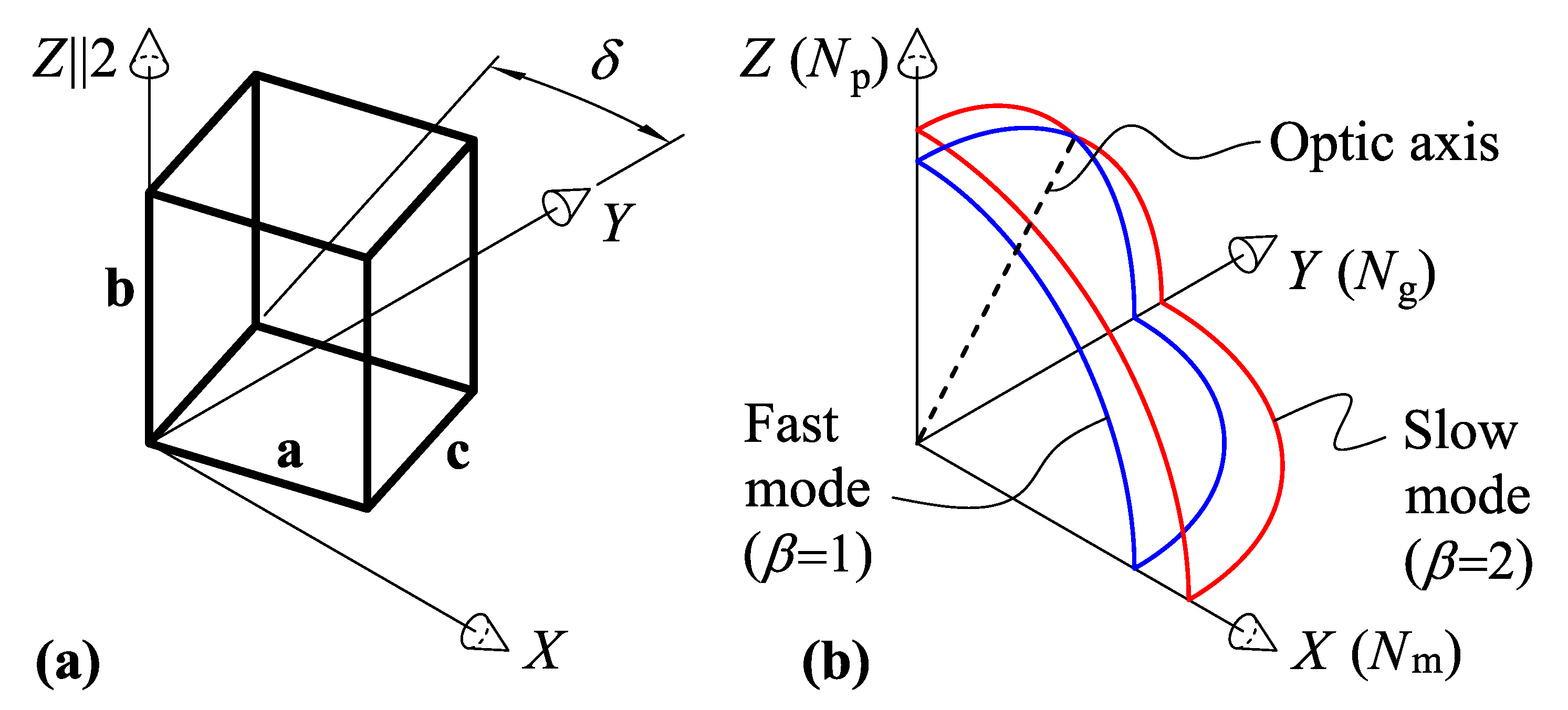
Figure 1. Dielectric properties of the KYW and KGW monoclinic crystals: (a) crystal’s unit cell; (b) refractive index surface cut-out. Z is the twofold symmetry axis; X Y is the symmetry plane; optic axis (dashed line) is on the Z Y plane.
Materials 15 08183 g001
Figure 2. Spatial diagrams for M 2 calculations: a selection of acoustic and optical wave propagation directions and polarizations of optical and acoustic waves. Dashed plane is orthogonal to the acoustic direction unit vector s . The locus of optical wave normal vectors m for the given acoustic wave vector direction s is shown with hatching.
Materials 15 08183 g002
Figure 3. KGW crystal, acoustic properties: (a) QL BAW mode velocity; (b) fast QS BAW mode velocity; (c) slow QS BAW mode velocity; (d) QL BAW diffraction coefficient; (e) fast QS BAW diffraction coefficient; (f) slow QS BAW diffraction coefficient. Conical acoustic axes of the crystal are marked with squares.
Materials 15 08183 g003
Figure 4. KGW crystal, maximum AO figure of merit, M 2 max ( α , β ) vs. BAW direction ( φ , θ ) : (a) QL BAW mode ( α = 1 ), fast optical mode ( β = 1 ); (b) fast QS BAW mode ( α = 2 ), fast optical mode ( β = 1 ); (c) slow QS BAW mode ( α = 3 ), fast optical mode ( β = 1 ); (d) QL BAW mode ( α = 1 ), slow optical mode ( β = 2 ); (e) fast QS BAW mode ( α = 2 ), slow optical mode ( β = 2 ); (f) slow QS BAW mode ( α = 3 ), slow optical mode ( β = 2 ). Conical acoustic axes of the crystal are marked with squares; optic axes are marked with red circles; directions orthogonal to optic axes are shown with dash-dotted lines.
Materials 15 08183 g004
Figure 5. KYW crystal, acoustic properties: (a) QL BAW mode velocity; (b) fast QS BAW mode velocity; (c) slow QS BAW mode velocity; (d) QL BAW diffraction coefficient; (e) fast QS BAW diffraction coefficient; (f) slow QS BAW diffraction coefficient. Conical acoustic axes of the crystal are marked with squares.
Materials 15 08183 g005
Figure 6. KYW crystal, maximum AO figure of merit: (a) QL BAW mode, fast optical mode; (b) fast QS BAW mode, fast optical mode; (c) slow QS BAW mode, fast optical mode; (d) QL BAW mode, slow optical mode; (e) fast QS BAW mode, slow optical mode; (f) slow QS BAW mode, slow optical mode. Conical acoustic axes of the crystal are marked with squares; optic axes are marked with red circles; directions orthogonal to optic axes are shown with dash-dotted lines.
Materials 15 08183 g006
Figure 7. KGW crystal, AO figure of merit for acoustic propagation on the X Y plane ( θ = 90 ° ): (a) QL BAW mode, fast optical mode; (b) QL BAW mode, slow optical mode; (c) QS BAW mode, fast optical mode; (d) QS BAW mode, slow optical mode. Solid lines—data from Figure 4; dashed and dotted lines—calculation according to Equations (10)–(13).
Materials 15 08183 g007
Figure 8. KYW crystal, AO figure of merit for acoustic propagation on the X Y plane ( θ = 90 ° ): (a) QL BAW mode, fast optical mode; (b) QL BAW mode, slow optical mode; (c) QS BAW mode, fast optical mode; (d) QS BAW mode, slow optical mode. Solid lines—data from Figure 6; dashed and dotted lines—calculation according to Equations (10)–(13).
Materials 15 08183 g008
Table 1. Maxima of the AO figure of merit in KGW and KYW crystals.
ParameterKGW CrystalKYW Crystal
BAW mode, α 1313
Polarization type and angle, γ QL ( 0.7 ° )QS ( 6.5 ° )QL ( 1.0 ° )QS ( 4.7 ° )
Velocity, v ( 10 3 m/s)4.332.224.732.38
Azimuthal angle, φ 62 ° 16 ° 58 ° 12 °
Polar angle, θ 90 ° 90 ° 90 ° 90 °
Optical mode, β 2222
Rotation angle, χ 0000
Figure of merit, M 2 ( 10 15 s 3 /g)15.827.813.824.5
Publisher’s Note: MDPI stays neutral with regard to jurisdictional claims in published maps and institutional affiliations.