
Fault Current Limitation in Electrical Power Networks Containing HTS Cable and HTS Fuse

 , and
, and
Abstract
:1. Introduction
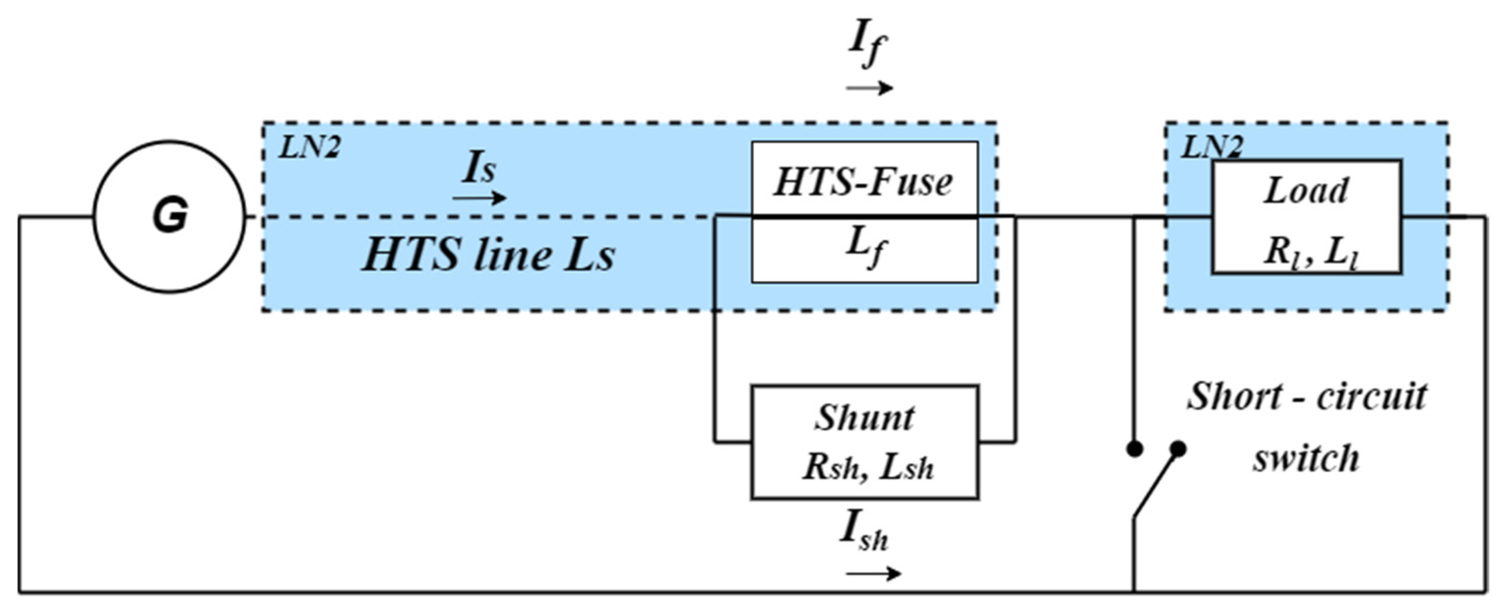
2. Model Circuit
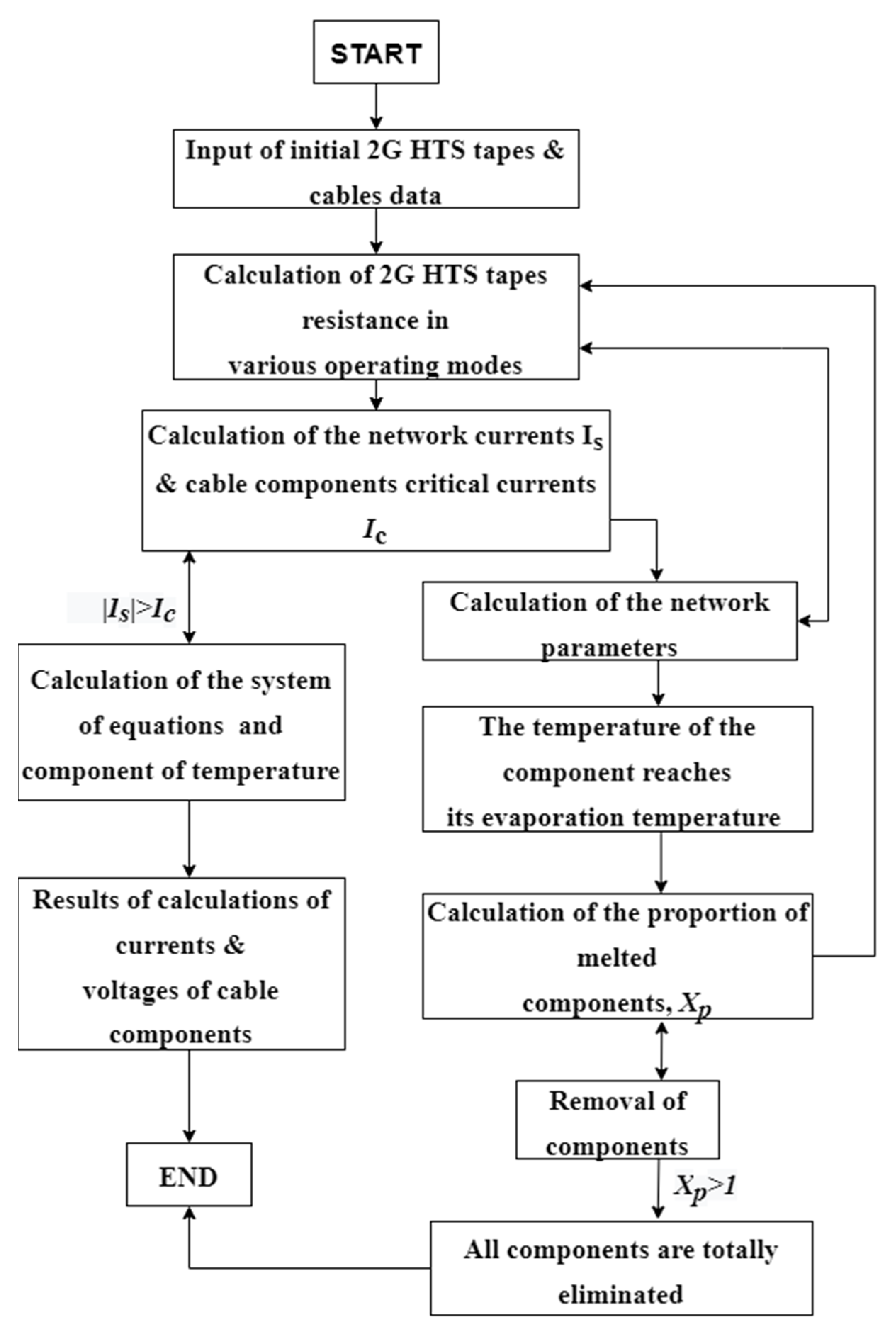
3. Algorithm of Calculations
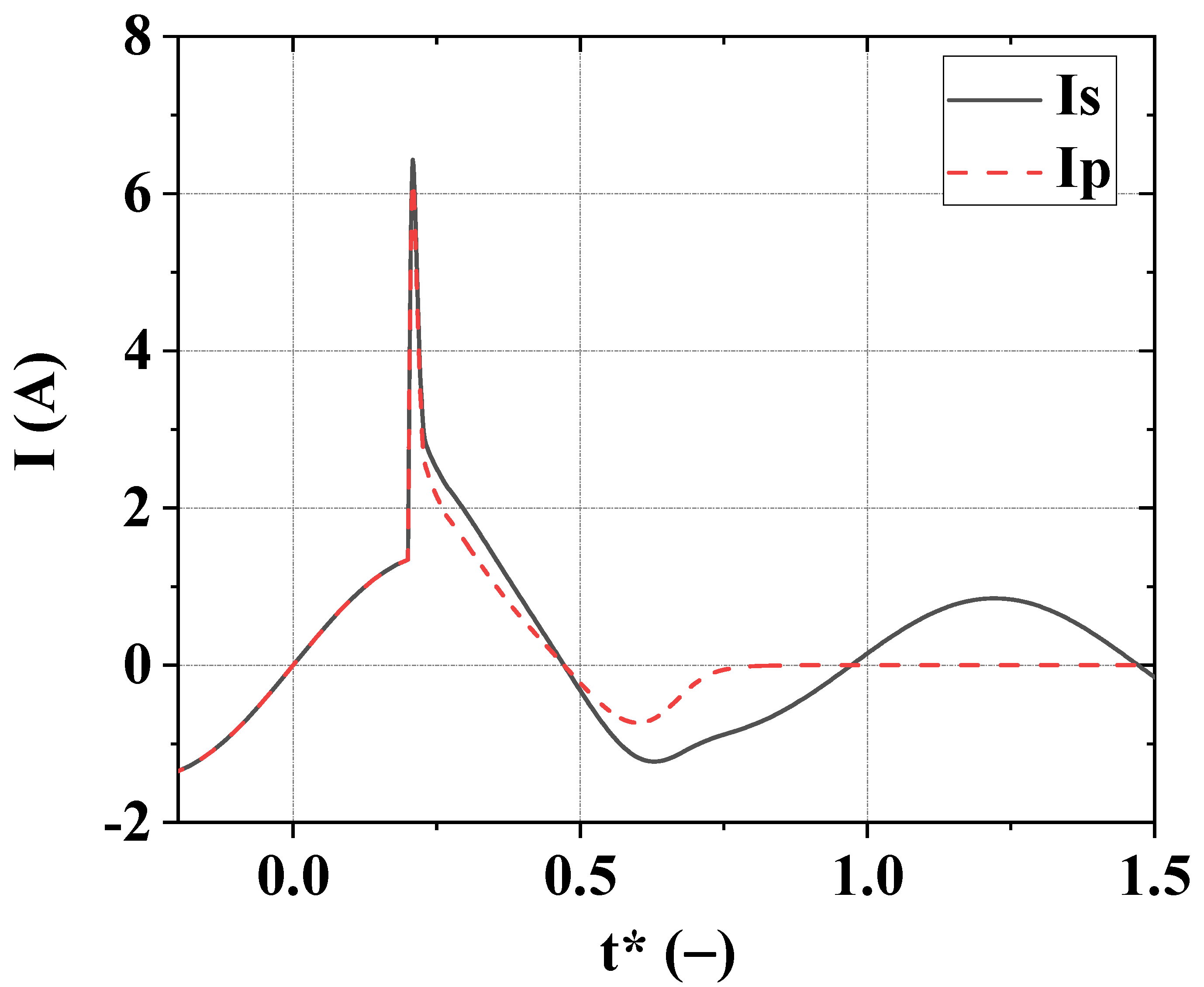
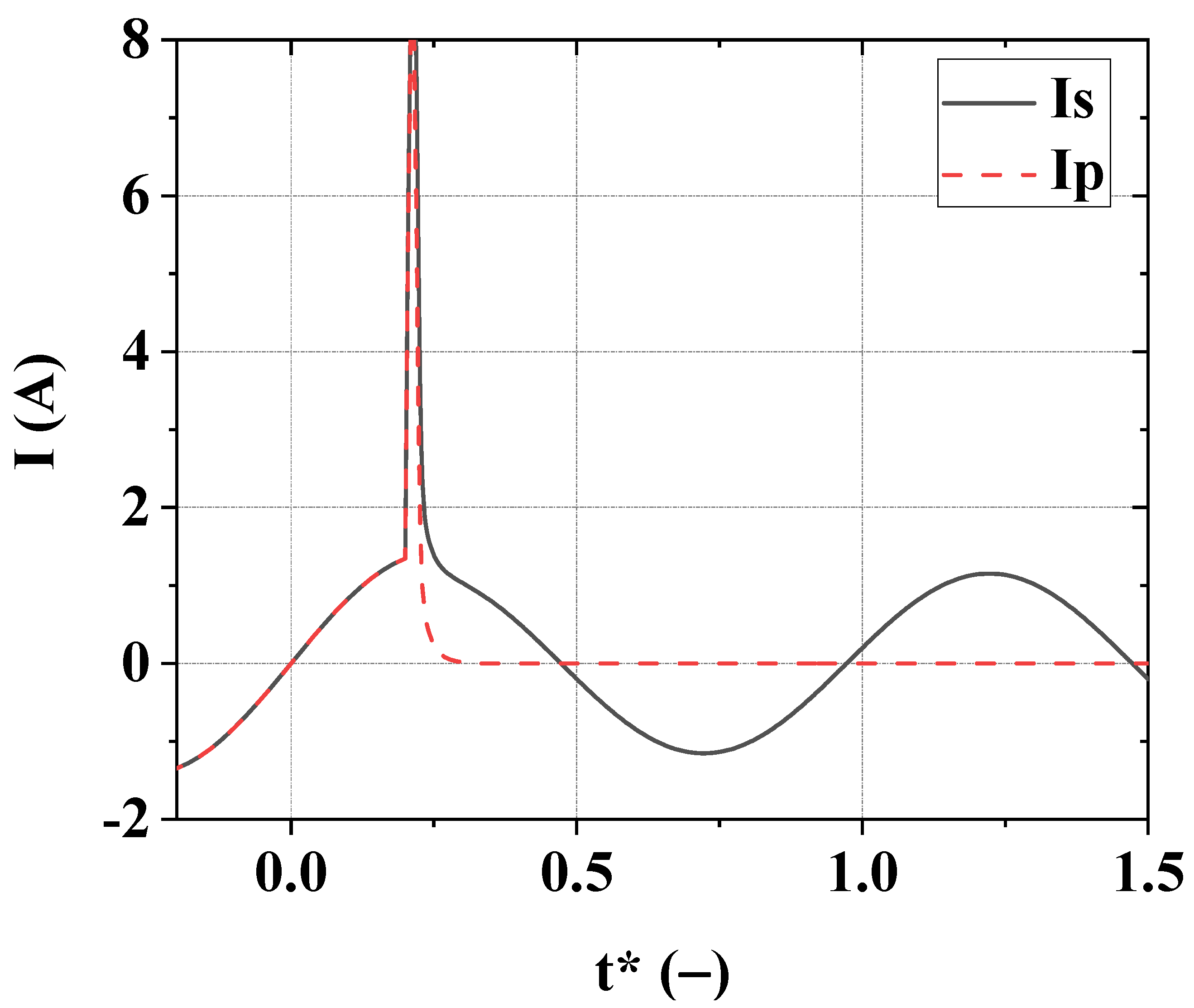
4. Results of Calculation
5. Discussion
5.1. Analysis of the Results
5.2. Preliminary Experimental Results
6. Conclusions
Author Contributions
Funding
Institutional Review Board Statement
Informed Consent Statement
Data Availability Statement
Acknowledgments
Conflicts of Interest
References
- Zhang, G.; Wang, H.; Qiu, Q.; Zhang, Z.; Xiao, L.; Lin, L. Recent progress of superconducting fault current limiter in China. Supercond. Sci. Technol. 2020, 34, 013001. [Google Scholar] [CrossRef]
- Neumueller, H.W.; Schmidt, W.; Kraemer, H.P.; Otto, A.; Maguire, J.; Yuan, J.; Folts, D.; Romanosky, W.; Gamble, B.; Madura, D.; et al. Development of resistive fault current limiters based on YBCO coated conductors. IEEE Trans. Appl. Supercond. 2009, 19, 1950–1955. [Google Scholar] [CrossRef]
- Kraemer, H.P.; Schmidt, W.; Cai, H.; Gamble, B.; Madura, D.; MacDonald, T.; McNamara, J.; Romanosky, W.; Snitchler, G.; Lallouet, N.; et al. Superconducting fault current limiter for transmission voltage. Phys. Procedia 2012, 36, 921–926. [Google Scholar] [CrossRef] [Green Version]
- Lee, S.R.; Lee, J.J.; Yoon, J.; Kang, Y.W.; Hur, J. Protection scheme of a 154-kV SFCL test transmission line at the KEPCO power testing center. IEEE Trans. Appl. Supercond. 2017, 27, 1–5. [Google Scholar] [CrossRef]
- Lee, S.R.; Ko, E.Y.; Lee, J.J.; Dinh, M.C. Development and HIL Testing of a Protection System for the Application of 154-kV SFCL in South Korea. IEEE Trans. Appl. Supercond. 2019, 29, 5602104. [Google Scholar] [CrossRef]
- Moyzykh, M.; Gorbunova, D.; Ustyuzhanin, P.; Sotnikov, D.; Baburin, K.; Maklakov, A.; Magommedov, E.; Shumkov, A.; Telnova, A.; Shcherbakov, V.; et al. First Russian 220 kV superconducting fault current limiter (SFCL) for application in city grid. IEEE Trans. Appl. Supercond. 2021, 31, 5601707. [Google Scholar] [CrossRef]
- Hong, Z.; Sheng, J.; Zhang, J.; Lin, B.; Ying, L.; Li, Y.; Jin, Z. The development and performance test of a 10 kV resistive type superconducting fault current limiter. IEEE Trans. Appl. Supercond. 2011, 22, 5600504. [Google Scholar] [CrossRef]
- Chen, Y.; Liu, X.; Sheng, J.; Cai, L.; Jin, Z.; Gu, J.; Hong, Z. Design and application of a superconducting fault current limiter in DC systems. IEEE Trans. Appl. Supercond. 2013, 24, 5601305. [Google Scholar] [CrossRef]
- Dai, S.; Ma, T.; Xue, C.; Zhao, L.; Huang, Y.; Hu, L.; Wang, B.; Zhang, T.; Xu, X.; Cai, L.; et al. Development and test of a 220 kV/1.5 kA resistive type superconducting fault current limiter. Phys. C Supercond. Its Appl. 2019, 565, 1253501. [Google Scholar] [CrossRef]
- Song, M.; Dai, S.; Sheng, C.; Zhong, L.; Duan, X.; Yan, G.; Huang, Y.; Chen, C.; Li, L.; Cai, L.; et al. Design and performance tests of a 160 kV/1.0 kA DC superconducting fault current limiter. Phys. C Supercond. Its Appl. 2021, 585, 1353871. [Google Scholar] [CrossRef]
- Zheltov, V.V.; Kopylov, S.I.; Arkhangelsky, A.Y.; Balashov, N.N.; Belkin, D.V.; Shigidin, A.B. High voltage fuse with the high temperature superconducting fuse box. Pat. Russ. Fed. 2021, RU206406U1, 1–7. Available online: https://patents.s3.yandex.net/RU206406U1_20210909.pdf (accessed on 29 October 2022). (In Russian).
- Arkhangelsky, A.Y.; Balashov, N.N.; Degtyarenko, P.N.; Shigidin, A.B.; Zheltov, V.V.; Zhemerikin, V.D. High voltage fuse with the high temperature superconducting fuse box and fault current limiter with this fuse. Pat. Russ. Fed. 2022, RU2770419C1. Available online: https://yandex.ru/patents/doc/RU2770419C1_20220418 (accessed on 29 October 2022). (In Russian).
- Chepikov, V.; Mineev, N.; Degtyarenko, P.; Lee, S.; Petrykin, V.; Ovcharov, A.; Vasiliev, A.; Kaul, A.; Amelichev, V.; Kamenev, A.; et al. Introduction of BaSnO3 and BaZrO3 artificial pinning centres into 2G HTS wires based on PLD-GdBCO films. Phase I of the industrial R&D programme at SuperOx. Supercond. Sci. Technol. 2017, 30, 124001. [Google Scholar] [CrossRef]
- Ovcharov, A.V.; Degtyarenko, P.N.; Chepikov, V.N.; Vasiliev, A.L.; Gavrilkin, S.Y.; Karateev, I.A.; Tsvetkov, A.Y.; Kaul, A.R. Microstructure and superconducting properties of high-rate PLD-derived GdBa2Cu3O7− δ coated conductors with BaSnO3 and BaZrO3 pinning centers. Sci. Rep. 2019, 9, 15235. [Google Scholar] [CrossRef] [Green Version]
- Degtyarenko, P.; Gavrilkin, S.; Tsvetkov, A.; Mineev, N.; Rudnev, I.; Ovcharov, A.; Chepikov, V.; Lee, S.; Petrykin, V.; Molodyk, A. The influence of BaSnO3 artificial pinning centres on the resistive transition of 2G high-temperature superconductor wire in magnetic field. Supercond. Sci. Technol. 2020, 33, 045003. [Google Scholar] [CrossRef]
- Molodyk, A.; Samoilenkov, S.; Markelov, A.; Degtyarenko, P.; Lee, S.; Petrykin, V.; Gaifullin, M.; Mankevich, A.; Vavilov, A.; Sorbom, B.; et al. Development and large volume production of extremely high current density YBa2Cu3O7 superconducting wires for fusion. Sci. Rep. 2021, 11, 2084. [Google Scholar] [CrossRef]
- Alferov, D.F.; Degtyarenko, P.N.; Dul’Kin, I.N.; Fisher, L.M.; Ivanov, V.P.; Kalinov, A.V.; Sidorov, V.A.; Voloshin, I.F. Thermal behavior of 2G HTS tape for use in resistive fault current limiters. J. Phys. Conf. Ser. 2010, 234, 032001. [Google Scholar] [CrossRef]
- Degtyarenko, P.N.; Dul’kin, I.N.; Fisher, L.M.; Kalinov, A.V.; Voloshin, I.F.; Yampol’skii, V.A. Thermoelectric instability induced by single pulses and alternating currents in second-generation superconducting tapes. Low Temp. Phys. 2011, 37, 101–106. [Google Scholar] [CrossRef]
- Degtyarenko, P.N.; Dul’kin, I.N.; Fisher, L.M.; Garas’ko, G.I.; Kalinov, A.V.; Vavilov, S.B.; Voloshin, I.F. Temperature rise of copper and HTSC tapes in liquid nitrogen by a step-wise current pulse. Phys. Procedia 2012, 36, 596–599. [Google Scholar] [CrossRef] [Green Version]
- Alferov, D.F.; Akhmetgareev, M.R.; Budovskii, A.I.; Bunin, R.A.; Voloshin, I.F.; Degtyarenko, P.N.; Yevsin, D.V.; Ivanov, V.P.; Sidorov, V.A.; Fisher, L.M.; et al. Superconducting dc current limiting vacuum circuit breaker. Phys. Procedia 2012, 36, 1264–1267. [Google Scholar] [CrossRef] [Green Version]
- Kopylov, S.; Balashov, N.; Degtyarenko, P.; Ivanov, S.; Samoilenkov, S.; Soldatenko, A.; Zheltov, V.; Vysotsky, V. Investigation of HTS power transmission lines stability conditions in short-circuit mode. IEEE Trans. Appl. Supercond. 2019, 29, 5401405. [Google Scholar] [CrossRef]
- Hazelton, D.W.; Selvamanickam, V.; Duval, J.M.; Larbalestier, D.C.; Markiewicz, W.D.; Weijers, H.W.; Holtz, R.L. Recent developments in 2G HTS coil technology. IEEE Trans. Appl. Supercond. 2009, 19, 2218–2222. [Google Scholar] [CrossRef]
- Samoilenkov, S.; Molodyk, A.; Lee, S.; Petrykin, V.; Kalitka, V.; Martynova, I.; Makarevich, A.; Markelov, A.; Moyzykh, M.; Blednov, A. Customized 2G HTS wire for applications. Supercond. Sci. Technol. 2015, 29, 024001. [Google Scholar] [CrossRef]
- Zhu, J.; Chen, S.; Jin, Z. Progress on second-generation high-temperature superconductor tape targeting resistive fault current limiter application. Electronics 2022, 11, 297. [Google Scholar] [CrossRef]


| Type of Cable | I*SC | I*0 | Δt [ms] | TCM K | TC(τ0) K |
|---|---|---|---|---|---|
| Cable 1 | 10.03 | 1.15 | 2.55 | 79.3 | 79.2 |
| Cable 2 | 10.00 | 1.15 | 2.66 | 97.0 | 79.1 |
| Cable 3 | 6.43 | 0.85 | 13.6 | 465 | 465 |
| Cable 4 | 7.19 | 0.99 | 5.42 | 427 | 427 |
Publisher’s Note: MDPI stays neutral with regard to jurisdictional claims in published maps and institutional affiliations. |
© 2022 by the authors. Licensee MDPI, Basel, Switzerland. This article is an open access article distributed under the terms and conditions of the Creative Commons Attribution (CC BY) license (https://creativecommons.org/licenses/by/4.0/).
Share and Cite
Degtyarenko, P.N.; Zheltov, V.V.; Balashov, N.N.; Arkhangelsky, A.Y.; Degtyarenko, A.Y.; Kovalev, K.L. Fault Current Limitation in Electrical Power Networks Containing HTS Cable and HTS Fuse. Materials 2022, 15, 8754. https://doi.org/10.3390/ma15248754
Degtyarenko PN, Zheltov VV, Balashov NN, Arkhangelsky AY, Degtyarenko AY, Kovalev KL. Fault Current Limitation in Electrical Power Networks Containing HTS Cable and HTS Fuse. Materials. 2022; 15(24):8754. https://doi.org/10.3390/ma15248754
Chicago/Turabian StyleDegtyarenko, Pavel N., Vladimir V. Zheltov, Nikolay N. Balashov, Andrey Yu. Arkhangelsky, Alena Yu. Degtyarenko, and Konstantin L. Kovalev. 2022. "Fault Current Limitation in Electrical Power Networks Containing HTS Cable and HTS Fuse" Materials 15, no. 24: 8754. https://doi.org/10.3390/ma15248754