1. Introduction
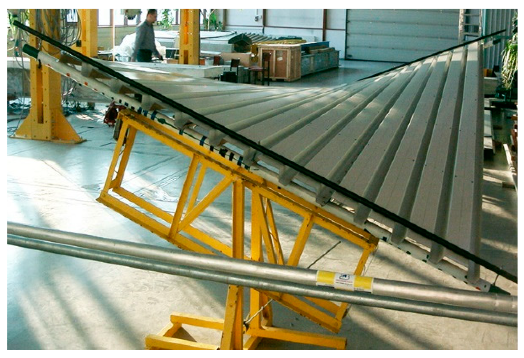
Nominally flat folded rectangular steel sheets are characterized by relatively low transverse bending and longitudinal torsional stiffness [
1]. This property enables the designer to exploit their diversified elastic transformations to shape diversified ruled shell forms [
2] (
Figure 1). However, there are significant geometric and material limitations in the formation of the shells due to a significant influence of these and other stiffnesses on the final shape of the transformed shells [
3]. The limitations very often result in significant values of stresses and, for the cases of high transformation degrees, significant values of strains. The intentional spatial shape deformations are called initial transformations [
2].
Further limitations are the straightness of all transformed shell folds and the rectangular shape of the sheets before transformation. On the one hand, these limitations simplify the process of designing and assembling the transformed roof shells. On the other hand, they induce the edge lines of the developed building models to be shaped in the form of various ruled surface sectors [
4] each of which is limited by a closed spatial quadrangle with vertex angles close to right [
2]. Due to the limited length of complete folded sheets used for roofing, single shell sheeting, being the result of joining the individual sheets with their adjacent longitudinal edges, can cover buildings with a span of up to 15–17 m. Therefore, for medium and long span roofs, edge roof structures composed of a few single folded transformed shells must be accomplished. The simplest way to shape the complex building structures is to determine special sums of many single shells transformed into parabolic-hyperbolic folded sectors, the edge lines of which are closed spatial quadrangles [
4,
5]. Moreover, all facade wall pieces of the structures have to be flat polygons (
Figure 2). In order to obtain a large variety of the designed building forms, the façade walls are inclined to the vertical.
Bearing in mind the above-mentioned assumptions and limitations, a novel polyhedral network called a reference network was developed [
6]. The network is used as a geometric material for modeling various unconventional forms of buildings characterized by plane-walled folded facades and edge roof structures composed of many transformed single folded shells. The structure of the layers used in the corrugated sheeting and their temperature affect the mechanical and geometrical properties of these coating segments [
7,
8].
Each configuration of the network is defined by an appropriate arrangement of many tetrads of vertices defining typical tetrahedral meshes connected by common triangular walls and adequately filling the three-dimensional space. These vertices, planes and side edges of the tetrahedra define the planes and edges of all facade walls of each modeled building. In the above planes, straight segments forming closed spatial quadrangles defining single shell roof are determined. The quadrangles constitute a polygonal network of the roof eaves structure and delimit all individual single roof shells. By varying the geometric properties of the polyhedral reference network and the polygonal network, in particular their subsequent meshes, some variety of building forms can be obtained, including multi-wall folded facades and multi-shell ribbed roofs [
9].
2. Critical Analysis of the Present Knowledge
Many diversified unconventional building forms and structural system intended for these forms are presented by Abdel and Mungan [
10]. The comprehensive classification of different types of a large number of unconventional structural systems is published by Saitoh [
11]. Most of these systems can be employed for structural systems supporting complex building forms characterized by folded elevation walls and multi-segment shell structures [
9].
Great theoretical possibilities in the field of shaping various ruled forms made up of the transformed folded sheets with an open profiles have resulted in extensive research development in the field of single shell sheeting transformations and creation of multi-segment shell structures [
2]. On the basis of the tests and analysis carried out, Bryan and Davis found that some significant material and technological limitations drastically reduce the diversification of the shell forms made up of transformed sheeting to a basic type of shallow hyperbolic paraboloids called hypars [
12].
However, the developed novel Reichhart’s method enables one to increase the diversity of shaping the unconventional roof shells and their structures composed of the nominally flat single-layer sheeting transformed into the position of the rigid skew directrices generating folded shell shapes [
3].
The results of the tests performed by Abramczyk [
13] indicate an important role played by a contraction of each transformed shell sheeting in shaping unconventional forms of buildings roofed with thin-walled folded sheeting transformed elastically into different ruled surfaces [
4]. Abramczyk has added the condition related to the central location of the contraction in all effectively transformed folded shells to the Reichhart’s algorithm.
The contraction of a roof shell can be modeled with a line of striction of a ruled surface. Thus, the Reichhart’s method was extended with the boundary condition related to the line of striction. This action should result in a rational shaping of the shell roof forms so that they could be characterized by the relatively high visual attractiveness and the minimum effort [
14]. If athe central location of the contraction, halfway along the length of each shell fold, is achieved by means of the arbitrary roof directrices, then the static-strength work of the transformed sheeting is stabilized and rationalized [
4]. In this way, a freedom of designing of free-form roof and elevation structures should be achieved [
2].
Biswas and Iffland [
15] elaborated two trivial systems of many congruent rectilinear shell units distributed over a sphere with the help of bundles of planes, where the complete transformed shells are made of revolved hyperboloids or right hyperbolic paraboloids restricted by spatial straight quadrangles. The proposed method for shaping ribbed structures composed of many congruent shells can be extended to create complex systems of many complete ruled shells separated by sets of planes containing their edge lines.
Prokopska and Abramczyk have carried out some simple systems of reference tetrahedrons to model complete free forms with oblique and folded plane elevations, and roofed with many transformed complete shell sectors [
16,
17]. The presented building structures are often composed of quarters of hyperbolic paraboloids arranged symmetrically in different configurations. The proposed diversified free form building structures roofed with complex corrugated shells are characterized by medium spans.
For the engineering developments, Abramczyk has proposed that each single shell segment is to be modeled with a sector of a warped surface [
2] limited by a closed spatial line composed of four straight segments contained in four planes of a polyhedral reference network [
6]. The planes of the reference network are a specific system dividing the designed roof structure into many complete shell segments arranged regularly in the three-dimensional space. In this way, all directrices of the shell sectors can be easily defined in these planes [
9].
Pottman has proposed a few comprehensive methods for shaping the systems of planes separating subsequent plane and smooth shell sectors arranged on different regular surfaces [
18]. If we want to shape transformed folded shell sheeting by means of the methods, their significant modifications taking into account the geometric and material constraints of the folded sheets must be performed. A few methods carried out by Attard [
19], Vlasow [
20] or Vasiri [
21] can also be implemented to design thin-walled sheeting subjected to large displacements. Samyn has described a method for creating the transformed folded shells made up of aluminum or PVC [
22].
The procedure for shaping complex building structures covered with transformed shell roof structures, the general form of which is characterized by a positive Gaussian curvature (
Figure 3), has been described by Abramczyk [
6] in a fairly accurate manner. This procedure has also been implemented in computer procedures [
23]. However, there is no analogous procedure and implementation where the overall form of the shell roof structure complies with the negative Gaussian curvature. This issue is analyzed in detail in this article.
The analogous universal systems of planes called polyhedral reference networks are utilized in this article. On the basis of these systems, some derivative systems, including polygonal or shell sector networks can be defined to achieve different free-form buildings characterized by complex folded elevation walls and multi-sector shell roof structures (
Figure 4) [
24].
To increase the attractiveness of the building edge shell structures and the whole urban system, Prokopska has proposed green plant gardens located on the shell roof segments and specific communication routes between the segments [
25]. The space around the designed building form, its physical form, urban greenways and cultural patterns of a whole spatial system have to be investigated. Sharma has described [
26] the relation appearing between the formation of the urban space and the social experience of the human self. Hasgül [
27] presents very important and interesting mathematics-based graph studies of patterns and shapes, thermal based photography and morphology related to the design syntax. Eekhout [
28] provides the results of his research in the field of forms taking account of the relationships occurring between the function, structure, internal and external texture, static-strength work and comfort conditions. The systematic morphology leads to the rationalization of each design process.
A very interesting approach to exploit the mechanical properties of new materials making it possible to shape original forms of elevation and roof structures is used by Marin et al. [
29], where the classical theory of elasticity developed by Green and Lindsay is extended in terms of the thermo-elasticity theory for dipolar bodies. The proposed novel method is based on a reciprocal theorem and not restrictive boundary conditions [
30].
A method for designing complex architectonic forms and engineering rational systems has been developed by Ręebielak [
31]. A number of attractive and effective structures adapted to human needs and the built environment has been provided by Tarczewski at al. [
32].
The methods for shaping single and complex shell roofs presented in the above literature should be directed towards making each roof from many nominally flat rectangular thin-walled corrugated steel sheets. In order to use these sheets for shell roof covering, shape transformations are required. It is advisable to shape the edge line of each shell segment in the form of a spatial quadrangle with corner angles close to straight and take into account the shape changes and limitations resulting from the shape transformations.
The given references refer to single shells or simple ribbed structures composed of several single shells. The innovative method developed by Abramczyk allows one for a significant increase in the variety of general building forms. However, the method is limited only to structures, where the arrangement of all individual shell segments is consistent with the properties of surfaces characterized by the positive Gaussian curvature (saddle surfaces). In some articles published by the researcher, the possibility of using various structures composed of many single shells distributed on regular surfaces with the negative Gaussian curvature (saddle surfaces) is identified.
However, a comprehensive novel method is presented in the present article and fills the gap in the current knowledge. This area is also important because torsional transformations of a single folded sheet lead to its various shell forms with the negative Gaussian curvature (saddle surfaces). After filling this gap, the authors intend to propose some innovative structural systems supporting the transformed folded shells and extend laboratory tests in the field of thin-walled folded sheeting transformed elastically into various forms of saddle surfaces.
4. The Method’s Concept
At first, a network
Γ composed of a number appropriately arranged tetrahedra
Γij must be defined. On the basis
Γ, a model
Σ of a complex folded building form can be created s as follows (
Figure 3). The walls of
Σ should be included in the planes of
Γ. The elevation edges of
Σ should be included in the side edges of
Γ. The eaves lines of each single shell of the roof structure must be contained in the planes of
Γ. The vertices of each eaves line must belong to the respective side edges of
Γ. In the presented procedure, these vertices have to be located between the vertices of
Γ.
The horizontal base plane Pb of the whole structure Σ must intersect all side edges of Γ. The intersecting points should also belong to the side edges and lie between the vertices of Γ. The division coefficients of the side edges of Γ by the vertices of the base and Σ must ensure appropriate positions of these vertices.
Construction of
Σ begins with the determination of the first central tetrahedral mesh
Γ11 of
Γ.
Γ11 is created on the basis of two arbitrary skew straight lines
u11 and
v11 perpendicular to each other, called the axes of
Γ11 (
Figure 5a). An arbitrary distance d
uv11 between
u11 and
v11 has to be adopted. It is measured along the straight line
n11 perpendicular to
u11 and
v11 between the points
Ou11 and
Ov11 of intersecting
n11 with
u11 and
v11.
In order to determine the positions of four vertices
WAB11,
WCD11,
WAD11 and
WBC11 of
Γ11, it is necessary to adopt the distance duv
11 between the above skew axes, the distance d
u11 between
WBC11 and
WAD11 and the distance d
v11 between
WAB11 and
WCD11. Based on the above assumptions, it is possible to calculate the coordinates of the above vertices in the orthogonal coordinate system [
x,
y,
z] and define four sides of
Γ11 (
Figure 5a).
A few subsequent meshes are located in orthogonal and diagonal directions of
Γ11 (
Figure 6) as follows. For the case of the mesh
Γ12, three vertices
WAB12,
WCD12 and
WAD12 are adopted to be identical to the vertices
WAB11,
WCD11 and
WBC11 of
Γ11, respectively. The axis
u12 of
Γ12 is assumed to be identical to
u11.
The location of the vertex
WBC12 is determined so that it is contained in the plane (
y,
z), distant from
WBC11 by the adopted value of d
v12 and distant from the axis
u11 by the height d
BC12 of the triangle
WBC12WCD12WAB12 measured from
WBC12, where
WBC12WCD12WAB12 should be congruent to
WBC11WCD11WAB11. The above activities lead to the creation of the form presented in
Figure 7a.
It is more convenient to control the shape of
Σ when the proportions dd
BC12 = d
v12/d
v11 and dd
BC12 = d
BC12/d
BC11 are used instead of the above-mentioned distances.
DBC12 is the distance of
WBC12 from
u12. Similarly,
dBC11 is the distance of
WBC11 from
u11. However, the distances can be calculated with the help of these coefficients. Adoption of the proportions between all meshes makes it possible to parametrize and control the shape of
Σ, and, consequently, create diversified forms
Γ and
Σ. For the mesh
Γ12 presented in
Figure 7a, dd
v12 = 1 and dd
BC12 = 1. The parametrization should lead to a division of the forms
Σ into different groups having similar geometric properties to predict the expected properties of the designed forms
Σ. The subsequent tetrahedra
Γ1j (
j = 1 to N, where N—the arbitrary natural number) belonging to the first orthogonal strip of
Γ are constructed similar to
Γ12.
All tetrahedra
Γi1 of the second orthogonal strip are formed in the same way as
Γ1j belonging to the first strip. The vertices
WAD21,
WBC21 and
WAB21 of the first
Γ21 tetrahedron,
Figure 6, are assumed to be identical to the vertices of
WAD11,
WBC11 and
WCD11 of
Γ11, respectively, when creating the network
Γ.
The fourth
WCD21 vertex of
Γ21 is constructed in the (
x,
z) plane in two arbitrary distances d
u21 from
WCD11 and d
CD21 from
v11. The method employed for parameterizing
Γ consists in defining a certain number of coefficients expressing the proportions between the distances of the vertices of the subsequently created
Γij’s axes. In the case of the
Γ21 tetrahedron, these proportions can be given as follows: dd
u21 = d
u21/d
u11 and dd
CD21 = d
CD21/d
CD11. The above activities lead to the construction of the form presented in
Figure 7b for which dd
u21 = dd
CD21 = 1.
In the presented algorithm, there is no freedom in determining the vertices of
Γ22 and other
Γij tetrahedra arranged in diagonal strips (for
i ≠ 1 or
j ≠ 1). For the
Γ22 tetrahedron, it is assumed that
WAD22 =
WBC11,
WBC22 =
WAD12,
WCD22 =
WCD21,
WAB22 =
WCD11. The above activities lead to the creation of the form presented in
Figure 8.
Generally, for diagonal tetrahedra, WADij = WBCi−1j−1, WBCij = WAD i−1j, WCDij = WCDij−1, WABij = WCDi−1j−1. A slight modification of the described procedure allows one to set WADij, WBCij, WCDij and WABij at any points of the respective network side edges, not only at the vertices of the previously created tetrahedra. This reduction of the limitations in relation to the Γ network leads to fundamental changes in the proportions between the overall dimensions and the size of the elements of the building model shaped. The description of the modified procedure for shaping the Γ network goes beyond the scope of this work.
Each network
Γ1 (
Figure 8) formed according to the proposed algorithm is composed of four tetrahedra
Γij (
i,
j = 1, 2) and can be extended to a symmetrical forms
Γ (
Figure 9a,b) for which (
x,
z) and (
y,
z) are the planes of symmetry. Thus,
Γ consists of four symmetrical parts
Γi (
i = 1 to 4). Based on the symmetrical reference network
Γ, a polygonal
Bv network is created to define a multi-shell roof structure.
Bv is created so that some respective relationships between the location of the vertices of the roof structure and the vertices of
Γ are adopted. The relationships are defined by means of the division coefficients of the pairs {
WABij,
WADij}, {
WABij,
WBCij}, {
WADij,
WCDij}, {
WADij,
WBCij} of each
Γij tetrahedron by the vertices of the eaves polygonal network
Bv, reference surface and the base of the form
Σ.
The first group {ddSAij, ddSBij, ddSCij and ddSDij} of the division coefficients is used to determine the points SAij, SBij, SCij and SDij on the side edges of Γ defining the reference surface ωr to search for the network Bv. The second group {ddAij, ddBij, ddCij and ddDij} of the division coefficients is used to determine the points Aij, Bij, Cij and Dij constituting the vertices of the polygonal network Bv. For the networks under consideration: (a) all acceptable values of the above-mentioned two types of the coefficients are in the range (0, 1), (b) the reference surfaces defined by the points SAij, SBij, SCij and SDij have negative Gaussian curvature. These limitations results from the geometric properties of the network Γ made. They proves the innovative nature of the performed analysis and the proposed procedure. In the case of the topics discussed so far in other articles, the values of these coefficients are within the range (1, +∞), and the reference surface is characterized by the positive Gaussian curvature. The case in which the values of the above-mentioned coefficients are within the range (−∞, 0) is similar to that with the range (1, +∞) but requires some modifications.
As it is convenient to define the positions of the vertices
Aij,
Bij,
Cij and
Dij with respect to the reference surface
ωr, it is rational to use coefficients taking account of the difference in the levels of the vertices belonging to
ωr and
Bv. For this purpose, the quotient of: (a) the respective values of the division coefficients of pairs {
WABij,
WADij}, {
WABij,
WBCij}, {
WADij,
WCDij} and {
WADij,
WBCij} by: (a) points
SAij,
SBij,
SCij and
SDij, and (b) points
Aij,
Bij,
Cij and
Dij can be calculated. However, the exact description of this problem is presented by Abramczyk [
24] and goes beyond the scope of the present article.
In the considered examples, the values of the partition coefficients used for the meshes Bvij lead to small or big folding of the examined roof structure covered with complete transformed shells separated by ribs. On the other hand, the base of the modeled building is flat and horizontal, so the z-coordinates of all base points, belonging to the Pb plane, are the same. The arbitrary level of the Pb plane is adopted as constant zP from the interval <0, dduv11>. The coordinates of all points PAij, PBij, PCij and PDij of the base belonging to the edges of the facade walls are obtained as a result of the intersection of the plane Pb with all Γ’s side edges.
The proportions taken into account, inter alia, the length, width and height of the entire Σ model and its fragments depend on the mutual position of the vertices of the reference polyhedral Γ network, the vertices of the polygonal Bv network, the base plane Pb and the reference surface used. These proportions are determined by the assumed values of the independent variables and the relationships between the values of the dependent and independent variables. In order to illustrate the impact of adopting different sets of values of the above-mentioned variables on the form of the Γ model, three examples of complex folded building forms covered with different shell roof structures characterized by the negative Gaussian curvature are presented in the next section.
5. Results
There are presented three examples showing the way of using the developed procedure in the process of shaping various unconventional complex forms of buildings, including the possibility of parameterizing these forms. In order to create the first tetrahedron
Γ11 of a polyhedral network
Γ, the values of the following parameters have to be adopted: (1) the distances d
v11 of two vertices
WBC11 and
WAD11 belonging to the first axis
v11 (
Figure 6), (2) the ratio dd
uv11 of the above distance d
uv11 to the distance d
v11 between the oblique axes
u11 and
v11, (3) the ratio dd
u11 of the distance d
u11 of two vertices
WAB12 and
WCD12 belonging to the second axis
u11 to d
v11. The values employed are given in
Table 1.
Identical values are adopted for the remaining congruent tetrahedra located in the orthogonal directions of the developed
Γ1 reference network. As a result of the respective composing of
Γ11,
Γ21 and
Γ12 a network
Γ1 can be created. The vertices of
Γ22 are lain at four vertices of the above tetrahedrons obtained previously. The co-ordinates of these vertices are given in
Table A1 in Appendix.
Then, to determine the positions of the vertices
SA11,
SB11,
SC11 and
SD11 of the first mesh of the reference surface
ωr lying in the side edges of
Γ11, the coefficients dd
SA11, dd
SB11, dd
SC11 and dd
SD11 constituting the division coefficients of the vertices of the
Γ11 tetrahedron by
SA11,
SB11,
SC11 and
SD11 should be adopted. The arbitrary values of these coefficients are presented in
Table A2 in the Appendix. The calculated values of the coordinates of these vertices are presented in
Table A3 in the Appendix.
Another operation provided for in the algorithm of the procedure is to determine the positions of the vertices
A11,
B11,
C11 and
D11 of the first mesh
Bv11 of the polygonal net
Bv1. For the form shaped (
Figure 10) the appropriate values of the coefficients dd
A11, dd
B11, dd
C11 and dd
D11 of the vertices of the
Γ11 mesh by
A11,
B11,
C11 and
D11 are adopted. These values are given in
Table A4 in Appendix. The
pz level of the base plane of the considered form is equal to 15,920 mm in [
x,
y,
z]. The individual vertices
PA11,
PB11,
PC11 and
PD11 of this base can be constructed as the points of intersection of the horizontal plane
pz with the side edges of
Γ1.
The following meshes of the Γ1, Bv1 nets and the reference surface are created in the same way. Alternatively, some vertices must be adopted at the positions of the corresponding vertices belonging to the previously constructed meshes.
A characteristic feature of the folded forms created by the procedure is the different inclination of the adjacent facade walls to the vertical. The form presented in
Figure 10a–c is characterized by two opposite façade walls directed in the
x-axis direction and inclined with their bases inwards, while the other two façade walls are inclined with their bases outwards.
On the other hand, a specific feature distinguishing this form from two following forms is the fact that its elevation walls with their bases inwards are much longer than two other elevation walls with bases inclined outwards. As a result, the form has an elongated elliptical shape when projected onto a horizontal plane, and the
x axis can be considered as the principal axis of the imaginary ellipse (
Figure 10c).
Three exemplary forms
Σ were created based on the same reference network
Γ. For these forms, appropriate and different values of three sets of the partition coefficients related to the points of the created reference surfaces, eaves networks and the bases were adopted. The first set was adopted so that the form
Σ has an elongated form in the direction of the axis
x in the projection on the plane (
x,
y) and the base plane is closer to the lower vertices of the reference network
Γ (
Figure 10).
The second set of the partition coefficients was adopted so that the second form
Σ has an elongated form in the direction of the
y axis in the projection on the (
x,
y) plane, the plane of the base is halfway between the upper and lower vertices of the network
Γ, and the points of the reference surface
ωr lie close to the base (
Figure 11). The third set of the partition coefficients was adopted so that the third form
Σ has a square form when projected onto the (
x,
y) plane, the base plane is halfway between the upper and lower vertices of the network
Γ, and the points of the reference surface
ωr lie further from the base than in the previous case (
Figure 12). The differences between the essential dimensions of the above forms are noticeable when comparing the respective views of each of the above-mentioned three forms.
The values of the relevant parameters and coordinates of these forms are given in
Table A2,
Table A3,
Table A4,
Table A5,
Table A6,
Table A7,
Table A8,
Table A9 and
Table A10. It is worth noticing that some geometric properties of two new forms, distinguishing them from the previously presented form are as follows. Two elevation walls of the form shown in
Figure 11, whose direction is in line with the
y-axis and the bases are tilted outwards, are much longer than the elevation walls titled with their bases inwards and running along the
x-axis. The
pz level of the base plane of the considered form is equal to 31,010 mm in [
x,
y,
z].
On the other hand, all façade walls of the form shown in
Figure 12 are of similar length regardless of whether their bases are tilted outwards or inwards. As a result, the projection of the third form onto a horizontal plane has a shape similar to a circle or a square. The differentiation of three above-mentioned general forms is generated by the deliberate differentiation of the values of the single division coefficients used. A discussion on this subject is presented in the next section. The
pz level of the base plane of the considered form is equal to 23,194 mm in [
x,
y,
z].
6. Discussion
The following relationships can be noticed from the observation of geometric properties of the orthogonal projections of three different structures presented in the previous section.
The inclination of the facade walls with their bases towards the inside or outside of a considered building form depends on the orthogonal directions of two types of axes
vij and
uij of a polyhedral reference network
Γ. For example, such a network is presented in
Figure 10,
Figure 11 and
Figure 12. If the considered dimension of the building form is consistent with the axis
v11 of the
Γ network, located above the base (
x,
y) of the form, as can be seen in
Figure 10a,
Figure 11a,
Figure 12a the projections show facade walls inclined towards the inside of the form. However, if the dimension of the form is considered orthogonal to the axis
v11 located above the base of the building, as it is shown in
Figure 10b,
Figure 11b,
Figure 12b, then the elevation walls tilted with their bases outside the considered form are visible.
The overall dimensions of a building form in all three directions of the axes of its local system [
x,
y,
z] are determined by the shape of the base edge line, the eaves line and their mutual position in the horizontal and vertical directions (
Figure 10,
Figure 11 and
Figure 12).
The locations of the edge lines of the base and the eaves of the created form depends on the position of their vertices in the side edges of the polyhedral reference network Γ. The more the levels of the eaves line vertices are closer to the level of the axis u11, the more the base is stretched along the axis x and compressed along the axis y. However, in order to obtain similar dimensions of the form (dimensions of the edge lines of the base and the eaves) in two orthogonal horizontal directions, the vertices of the eaves edge and the vertices of the base edge should be placed at levels equidistant (or close to such) from the level of the horizontal plane passing through the midpoint of the straight line normal to u11 and v11, on both sides of this middle plane. All levels are defined by horizontal planes and their distances from the principal plane (x, y).
The shape of the eaves line Bv of a building form may be generated by the division coefficients of the respective pairs of vertices belonging to the polyhedral reference network Γ by the vertices of Bv. On the other hand, the shape of the base edge line can be determined by the coefficient defining their plane level. Control of the mutual position of the eaves line Bv and the base edges can be done by double division coefficients of the vertices of Γ by the eaves vertices and the base vertices. This issue goes beyond the scope of the paper.
To obtain an elongated horizontal projection of a building base along the axis
x, the base level coefficient dd
P should be taken significantly lower than 0.5 (
Figure 10). To generate a horizontal projection of the building base elongated along the axis
y, the coefficient dd
P should be assumed significantly greater than 0.5. However, in order to obtain a horizontal projection of the building base with a comparable length of two overall dimensions measured in the
x and
y directions, the dd
P coefficient should be adopted close to 0.5.
If the examined polyhedral reference network
Γ has properties analogous to the networks presented in
Figure 11 and
Figure 12, i.e.,
u11 is identical to
x of [
x,
y,
z],
v11 is perpendicular to
u11 and distant by d
uv11 from
z, then the following are true. To obtain an elongated plan view of the designed eaves line along the axis
x, the coefficients dd
Aij, dd
Bij, dd
Cij and dd
Dij should be taken significantly less than 0.5. To obtain an elongated plan view of the eaves line along the axis
y, the coefficients dd
Aij, dd
Bij, dd
Cij and dd
Dij should be significantly greater than 0.5. To generate a horizontal projection of roof eaves line characterized by comparable overall dimensions measured in the
x and
y directions, the arbitrary division coefficients close to 0.5 should be taken.
In order to generate an innovative form of a building having two façade walls inclined inwards and another two outwards of the form, and being close to a circle when projected onto a horizontal plane, the absolute values of the differences ddAij—0.5, ddBij—0.5, ddCij—0.5 and ddDij—0.5 should be adopted equal or close to an absolute value of the difference ddP—0.5, especially for all central meshes of the net Γ.
The examined general forms are to be influenced by corrugation of the polygonal eaves network Bv generated by the size of the differences between: (a) the division coefficients of the vertices of polyhedral reference network Γ by the vertices Aij, Bij, Cij and Dij of Bv, and (b) the division coefficients of the same vertices of Γ by the corresponding points SAij, SBij, SCij and SDij of a reference surface. In addition, these forms are to be influenced by the ratio between the size of this corrugation and the height of the entire form, which depends on the division coefficients of the vertices of the polyhedral reference network by points belonging to three groups: (a) base vertex group, (b) reference surface point group, and (c) eaves vertex group. The discussion about the influence of some important proportions between the values of the above-mentioned coefficients and the geometrical properties of the building forms shaped goes beyond the scope of the article and requires definition of the so-called multiple division coefficients.


