3.1. Mathematical Model of the Stability of a Conventional Vehicle and the E3-Cycle
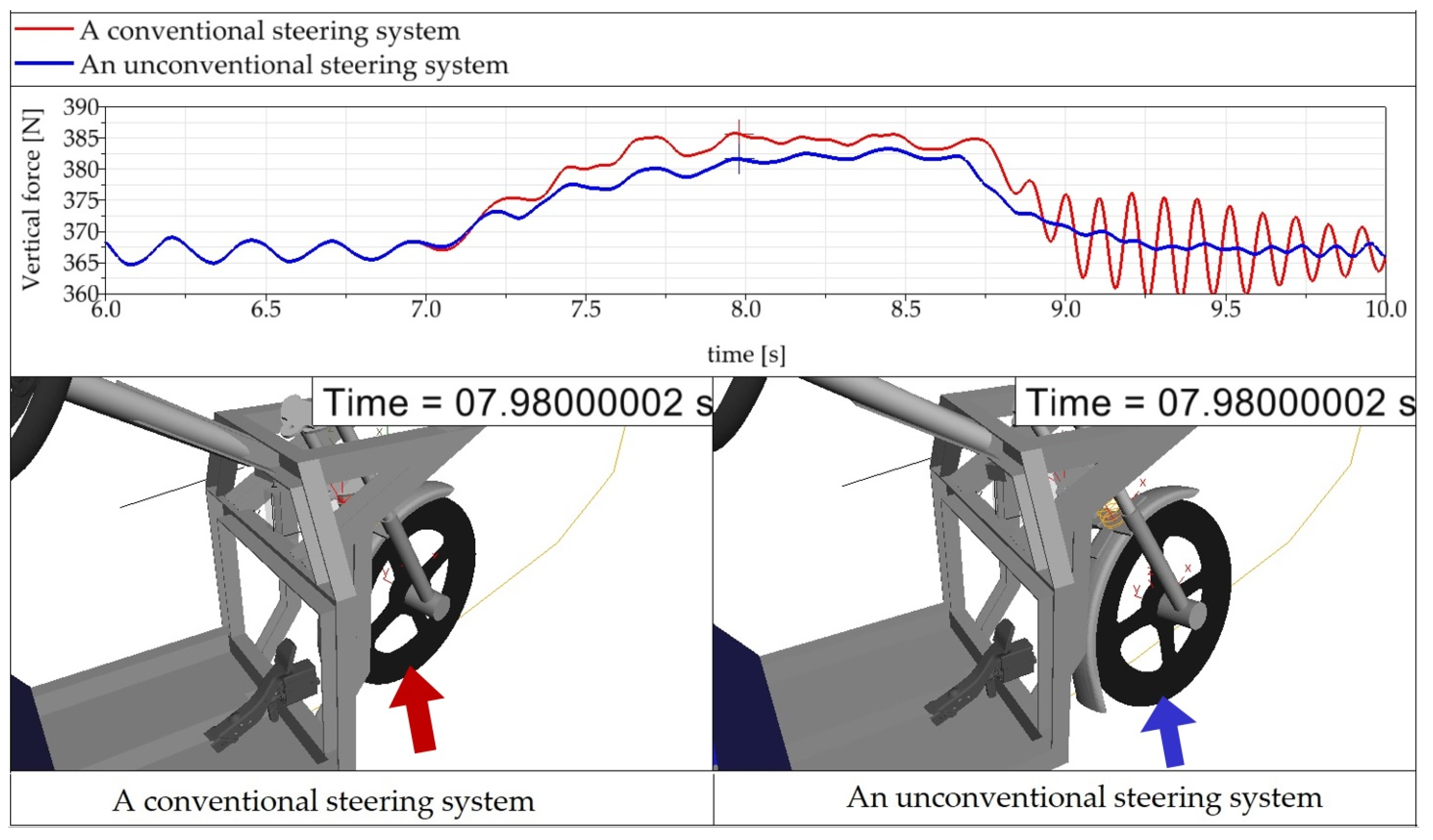
The basic control of the steering mechanism in an electric tricycle with conventional steering is the axial rotation of the wheel as well as in motorcycles or bicycles. Single-track vehicles, in the course of cornering, compensate for the effects of centrifugal force by tilting in the opposite direction of that force. Inasmuch as the rear axle of the E3-cycle is two-wheeled, tilting is almost completely limited. As a result of noncompliance with the conditions, namely, the speed appertaining to a given turning radius, the centrifugal force may reach a critical value, which the vehicle-rider system will no longer be able to overcome. Consequently, the stability conditions will be violated. In terms of these undesirable circumstances, the vehicle is at risk of overturning. The necessary factors considered in the calculation include the wheel track, the weight distribution of the vehicle components or the approximate position of the total center of gravity, the rider ergonomics, and the design of the vehicle [
21]. The mathematical notation of the above emerges from the schema depicted in
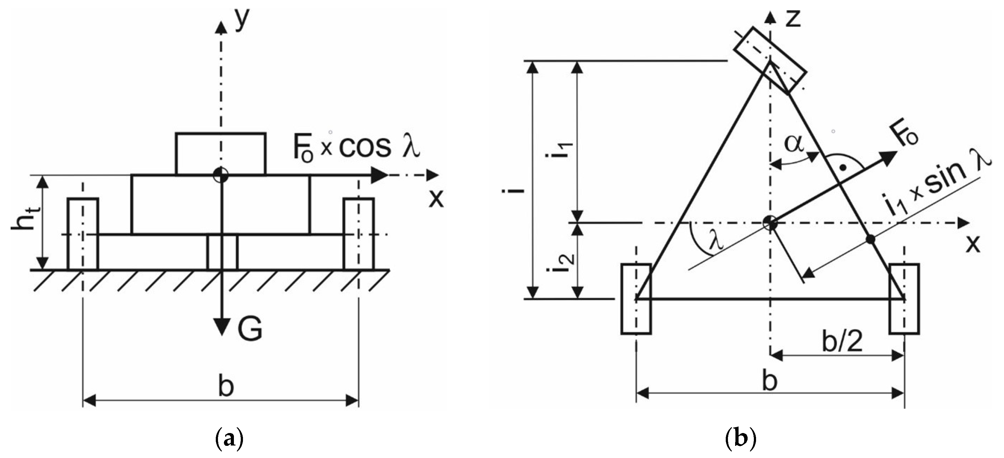
Figure 8. The stability condition for a conventional three-wheeled vehicle is given by Formula (1):
where
G is the weight of the vehicle;
Fo is the centrifugal force during riding on a curve and
i1,
α,
λ, and
ht are the parameters of the vehicle depicted in
Figure 9.
The congruence of angles
α and
λ emerges from
Figure 9b:
where
α is the constant angle given by the design of a conventional three-wheeled vehicle;
λ is the constant angle given by the design of a conventional three-wheeled vehicle.
Equation (3) applies for the vehicle’s center of gravity:
where
G is the weight of the tricycle;
m is the mass of the vehicle;
g is the gravitational acceleration.
Equation (4) applies for the centrifugal force of the vehicle
Fo:
where
Fo is the centrifugal force acting on the vehicle during cornering;
m is the mass of the vehicle;
a is the acceleration of the vehicle.
Equation (5) is applied for the acceleration of the vehicle
a:
where
v is the instantaneous speed of the vehicle and
Rz is the radius of a corner.
Applying Equations (2)–(5) into Formula (1), we get (6):
Subsequently, the Formula (6) for calculating the maximum speed
vmax at which the vehicle can move on a bend with a given radius
Rz is obtained from the Formula (7):
where
vmax is the maximum (safe) speed of the vehicle moving on the bend;
g is the gravitational acceleration;
Rz is the radius of the corner;
b is the track width of the vehicle;
i1 is the distance of the vehicle’s center of gravity from the centerline of the front wheel;
ht is the height of the vehicle’s center of gravity above the ground;
i is the wheelbase of the vehicle.
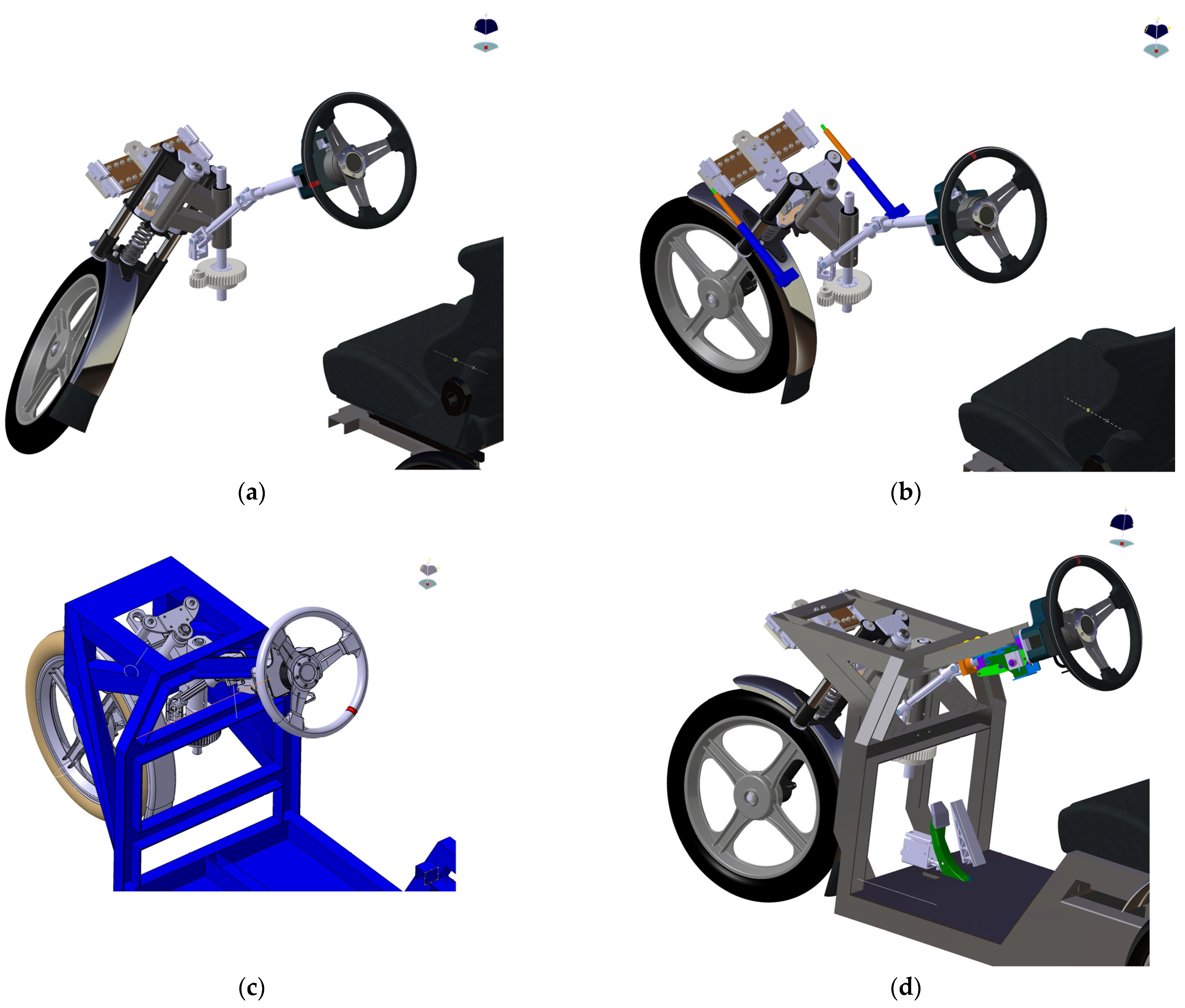
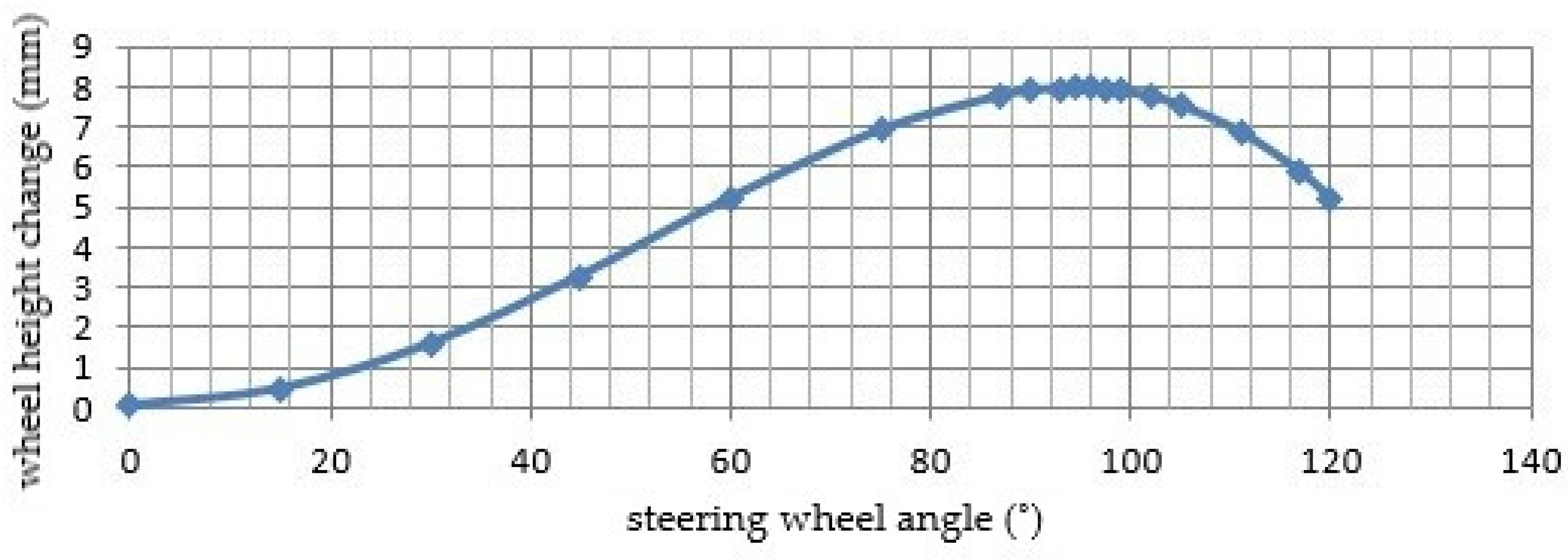
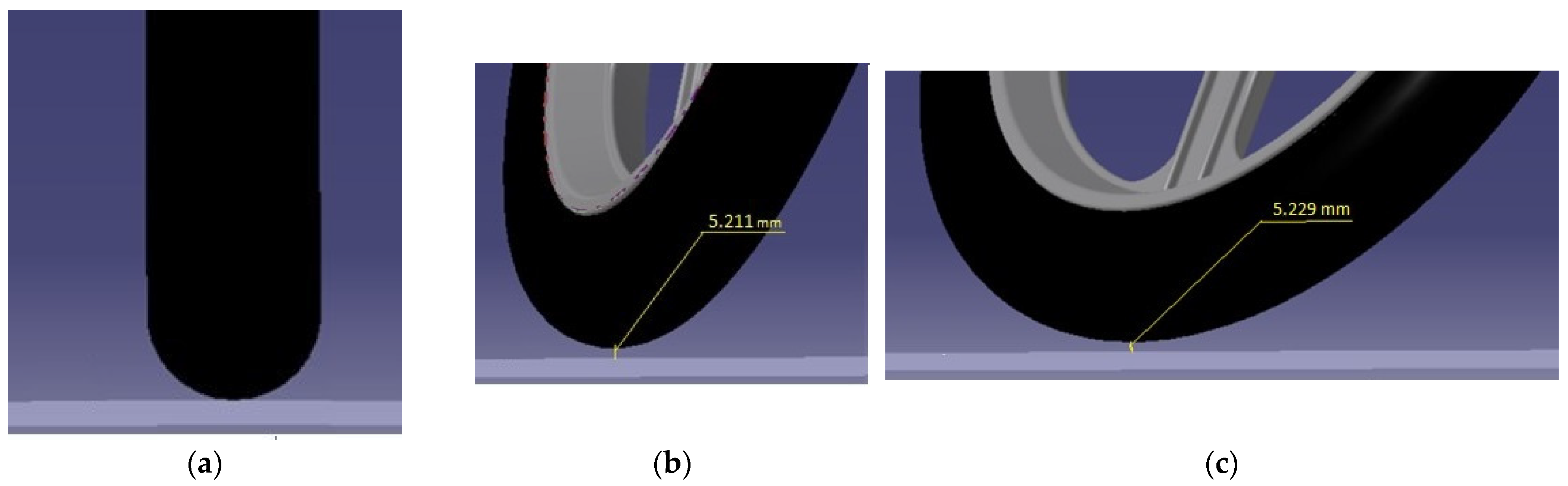
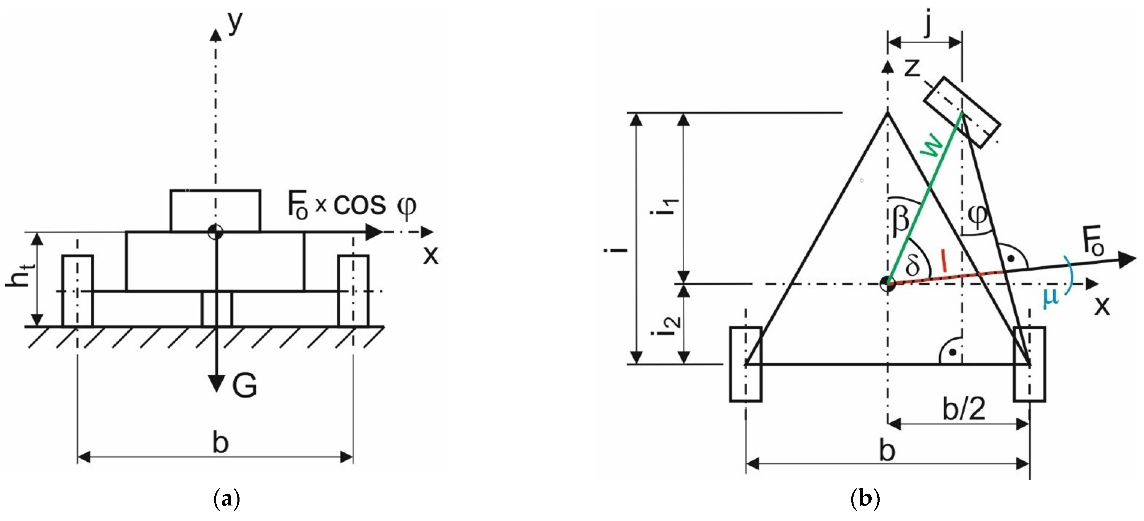
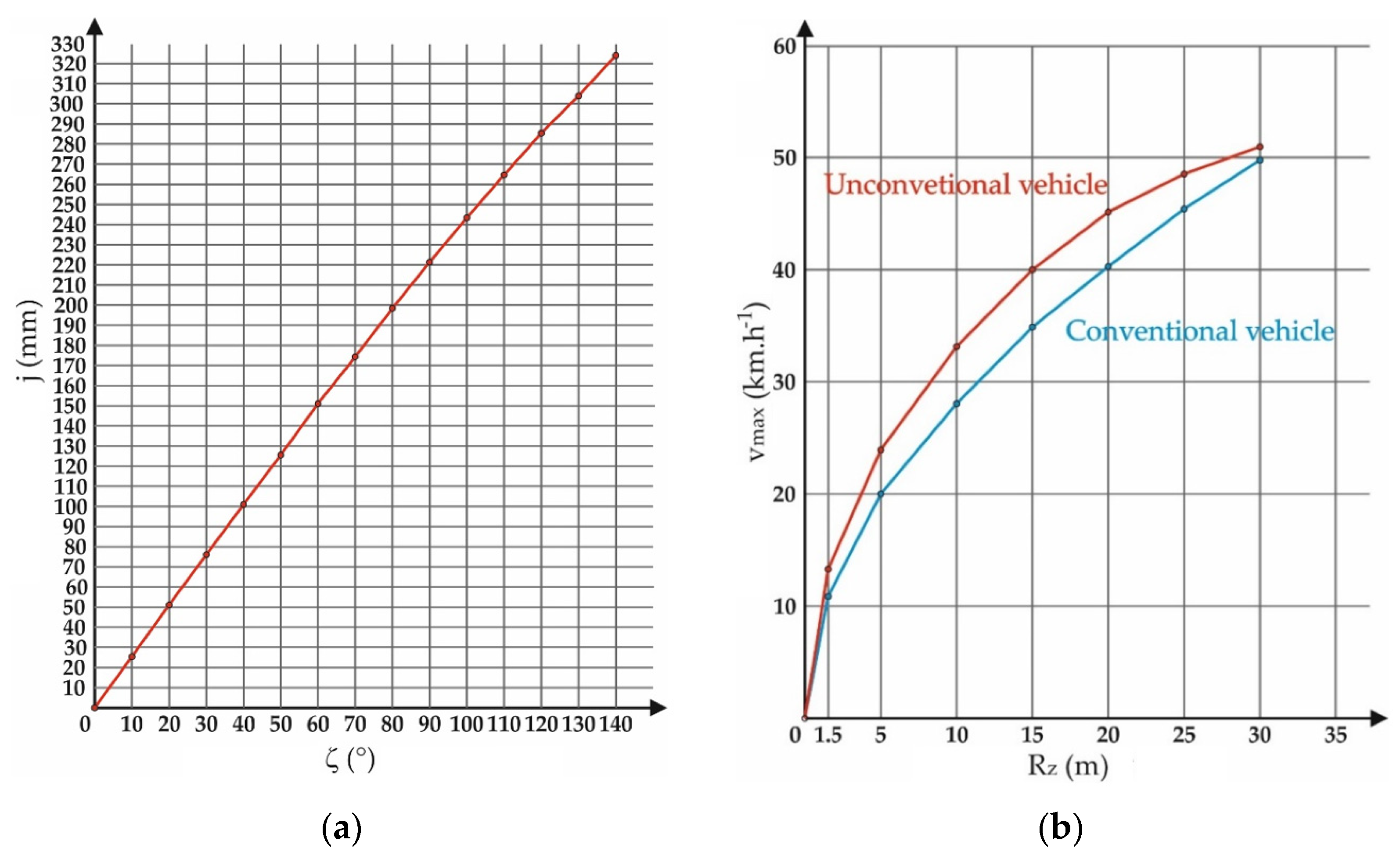
The steering mechanism of the E3-cycle differs from the conventional configuration in particular in terms of riding dynamics. By virtue of the action of the gearing, which connects the suspension of front wheel or more precisely steered wheel with a suitably designed structure, the steering axle is able to deviate relative to the vehicle’s central axis by a value of “
j” (
Figure 10), namely in the process of front wheel turning during the steering wheel turn. This compound motion increases the length of arm l through which the vehicle’s gravitational force is applied. As a result, the value of the moment of gravitational force
G rises. This is a mechanism that affects the stability of the vehicle. The notation
j represents the value by which the front wheel is extended to the outside of the curve. The value of
j varies with the steering wheel angle
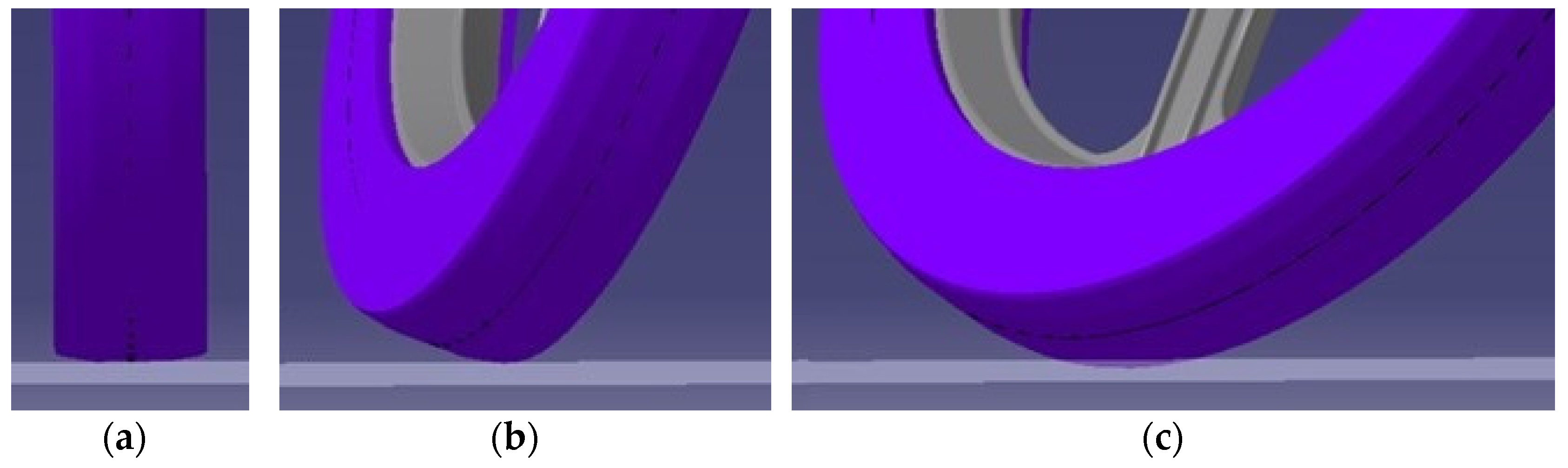
ζ. Wheel extension occurs while the wheel is turning. The E3-cycle is able to make a passage on the curve with a minimum value of curve radius of
Rz = 1.5 m, whereby it is necessary to turn the steering wheel by
ζ = 140°. In that case, the wheel deviates by
j = 323.9 mm.
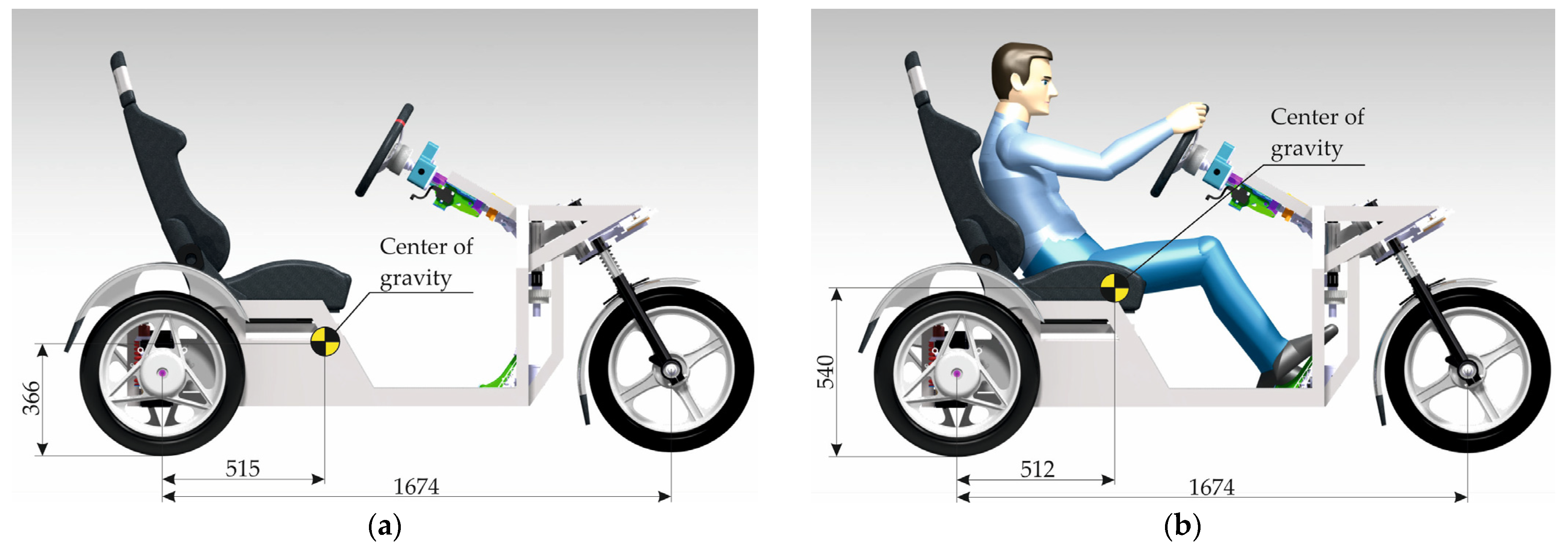
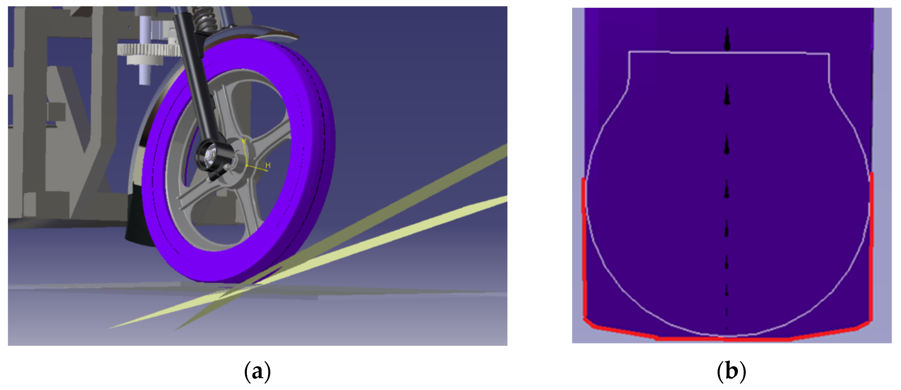
The center of gravity of the E3-cycle is located under the rider’s seat; therefore, closer to the rear axle of the vehicle, in the middle, as low as possible. The E3-cycle is fitted with wheels with a 260 mm radius tire. The position of the center of gravity is 93.9 mm above the wheel centerline (
Figure 11). For the sake of summing these values, the position of the center of gravity from the pad is
ht = 353.9 mm.
The way the E3-cycle passes through the curve affects its stability condition (8). By means of this mathematical scheme, it is possible to observe how large a centrifugal force effect the E3-cycle can overcome. The stability condition for the E3-cycle from
Figure 10 is given by Formula (8):
where
G is the weight of the tricycle;
l is the geometric variable dependent upon the parameter
w;
Fo is the centrifugal force acting on the vehicle during cornering;
μ is the variable angle dependent upon the value of the wheel deflection
j (equivalent to the angle
φ);
ht is the height of the vehicle’s center of gravity above the ground.
Equation (9) emerges from
Figure 10:
where
w is the variable dependent upon the value of the wheel deflection
j;
δ is the variable angle dependent upon the value of the wheel deflection
j.
Moreover, the distance
w is calculated from the Pythagorean theorem as (10):
where
i1 is the distance of the vehicle’s center of gravity from the centerline of the front wheel;
j is the variable distance of the deflection of the front wheel of the vehicle from the longitudinal axis of symmetry.
Further, the angle
δ is calculated as follows:
and the angle
β is calculated according to Equation (12):
Finally, the angle
μ is obtained using Equation (13):
where
μ is the variable angle dependent upon the value of the wheel deflection
j (equivalent to the angle
φ);
b is the track width of the vehicle;
j is the variable distance of the deflection of the front wheel of the vehicle from the longitudinal axis of symmetry;
i is the wheelbase of the vehicle.
Substituting Equations (9)–(12) into Formula (8), the Equation (14) is acquired:
from where, after substituting Formulas (3)–(5), the Equation (15) for calculating the maximum speed
vmax is attained:
where
vmax is the maximum (safe) speed of the vehicle moving on the bend;
g is the gravitational acceleration;
Rz is the radius of the corner;
l is the geometric variable dependent upon the parameter
w;
μ is the variable angle dependent upon the value of the wheel deflection
j (equivalent to the angle
φ);
ht is the height of the vehicle’s center of gravity above the ground.
Equations (7) and (15) are simplified analytical mathematical models. On the basis of these models, the analysis of the maximum speeds of the conventional and unconventional tricycle will be executed along with comparison of these speeds.
3.2. Numerical Simulation of Eigenfrequencies and Stresses of the E3-Cycle Frame
The frame of the E3-cycle is its basic supporting part. It has been designed to ensure the precise positioning of the individual structural units in order to prevent collisions and damage to the elements (reliable operation). The frame carries all types of loads [
22]. Accordingly, significant requirements are placed on the E3-cycle frame based on safety and purposefulness. The shape, dimensions, and material are taken into account in addition to the strength properties and deformations of the frame. Consistency, integrity, eigenfrequencies, and eigenmodes were scrutinized in the graphical environment of Ansys 2019R3. The Ansys software is one of the most widely used software for performing static analyses of mechanical components using the finite element method (FEM) [
23,
24,
25].
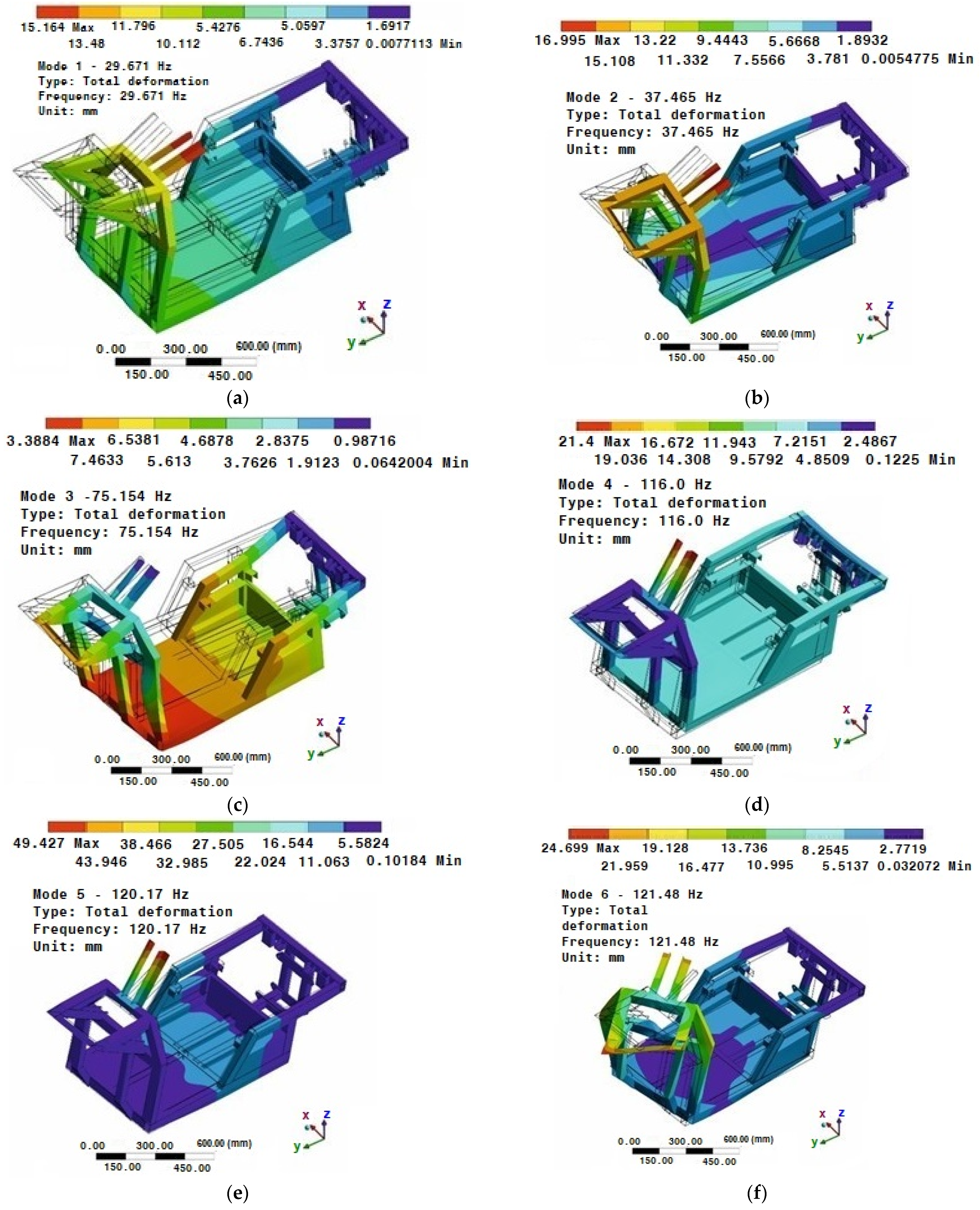
The modal analysis provides the primary information related to the verification and validation of the correctness of the frame model setup and its dynamic properties. In addition, modal analysis can indicate eventual shortcomings of the analyzed structure; thus, optimize the structure before production. For the sake of the proposed vehicle as a transportation device, it is indispensable to consider additional dynamic stresses over a relatively wide range of excitation frequencies. For this reason, a modal analysis was performed.
The modal analysis was carried out on a model without defined internal damping. The boundary conditions for the modal analysis were determined in the form of removing all degrees of freedom. The first 6 mode shapes (eigenfrequencies) were examined. In terms of the eigenfrequencies, the maximum response of the structure occurs at the minimum input energy. This may cause excessive wear or even failure of the structure.
From a historical point of view, calculation procedures are known to greatly simplify the nature of the component. Today, the widespread finite element method makes it possible to simplify the procedure for verifying the strength of a component. As it will be seen in
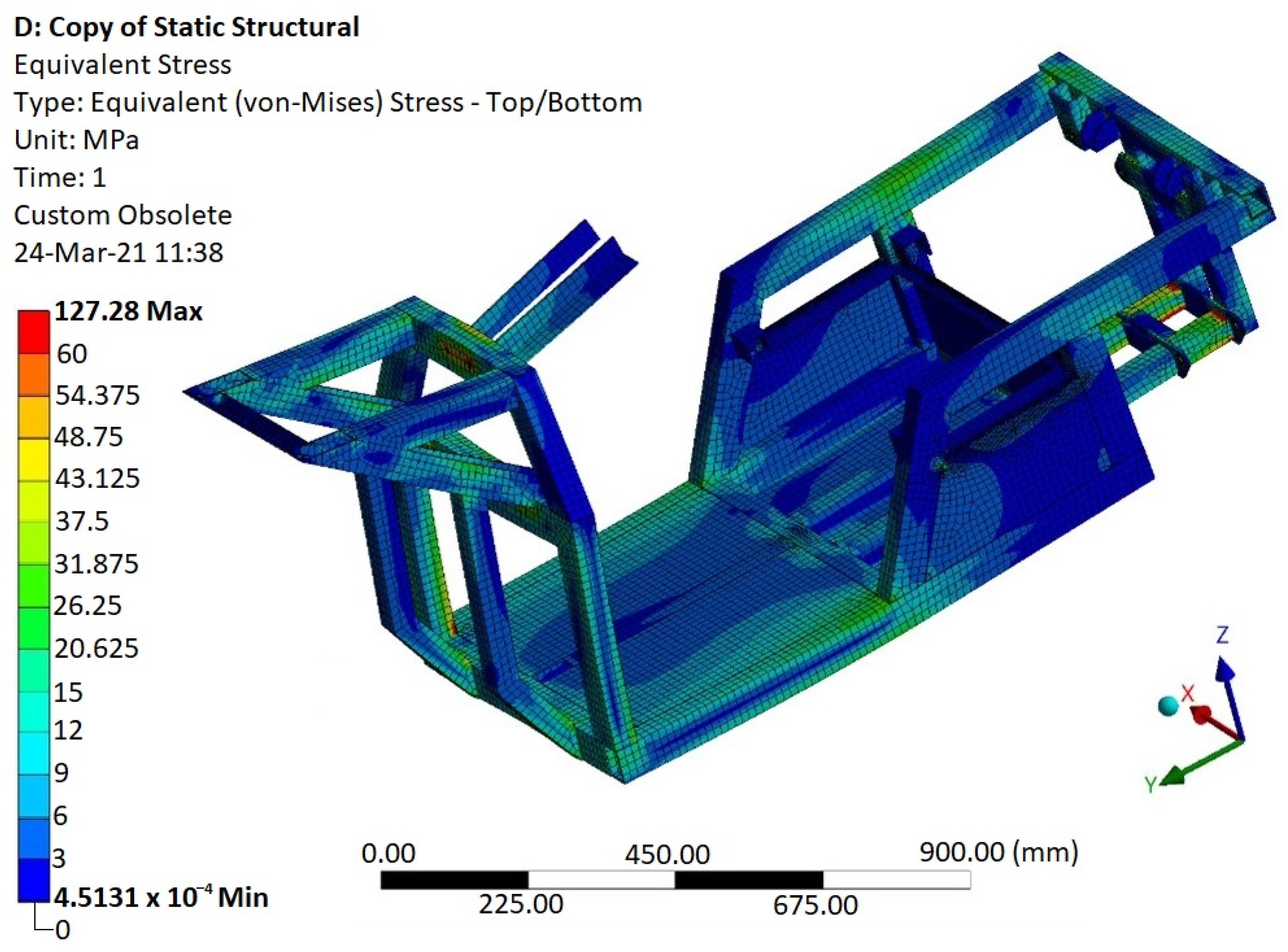
Section 4.2, this group of finite elements forms a mesh covering the body. The frame structure is made up of profiles and plates. Therefore, it is convenient to reduce the volume elements to shell elements. The advantage of this step is that the thickness of the shell element can be easily changed. In the case of unsatisfactory results, the parameters of the input material can be rapidly changed. This eliminates the need for manual modification of the model in an external modeling program. The input parameters are the conditions that determine the stress of the model, the material properties, and the input geometry of the structure from the external modeling program. Boundary conditions were defined on the basis of possible situations that arise during the operation of the equipment. Thus, conditions comprised loads from internal components, self-weight, and from the rider along with the seat. The removal of degrees of freedom was made at the points where the vehicle came into contact with the road. Additionally, the material properties were specified as a homogeneous isotropic material. Since it was an aluminum alloy, parameters such as Young’s modulus, Poisson’s ratio, and density were considered in the calculation.
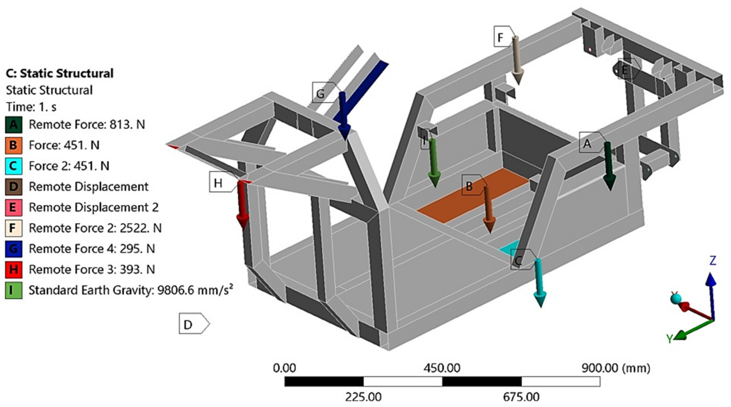
The geometry of the E3-cycle frame was imported to Ansys software from the Catia V5R20 software. Linear tetrahedron elements were used to mesh the model. In terms of numerical calculation, the locations of the stress concentration load induced by the vehicle operation were detected. It was also feasible to determine the values of the bending and torsional deformations that arose. The torsional stiffness as well as the flexural stiffness were determined in the FEM software Ansys. The distinct analyses that were performed on the E3-cycle needed the force applied to the frame. The force, which was employed to analyze the vehicle, depended on the weight of the vehicle (the mass of the E3-cycle concentrated at its center of gravity is 151.5 kg) (
Figure 11) and the weight of a model of the rider (rider mass is 130 kg) acting on the vehicle at the time of its operation. Gravitational forces are mainly responsible for bending the frame (also during braking and acceleration in the straight direction [
26]), while in the course of cornering, the dominant forces (centrifugal) acting on the vehicle are chiefly related to the torsional stiffness of the vehicle [
27].
The total mass of the vehicle with the rider was 281.5 kg. Because of safety, a 2∙g acceleration of gravity was considered. Then, the force exerted on the frame is double the weight of the vehicle with rider. The force is subsequently redistributed into the attachments of the frame and vehicle components (explained in
Figure 12 and
Figure 13). Torsional stiffness expresses how much resistance a given cross-section of the frame structural units produces to the torsional forces acting on it [
28,
29,
30,
31]. Flexural analysis helps in determining the ductility of EN AW6063 aluminum alloy and, moreover, how it will resist a break when subjected to loading forces. The torsional stiffness of the frame is one of the crucial factors in its design. Inasmuch as the torsional stiffness of the frame determines its torsion, it significantly influences the suspension design of a vehicle. Flexural stiffness defines the frame efficiency, as the energy lost during acceleration due to chassis bending; this can be discovered by dint of flexural analysis. In vehicle suspension design, the frame is considered to be absolutely rigid. Therefore, it is essential to determine the displacement caused by the torsional forces acting on the chassis.
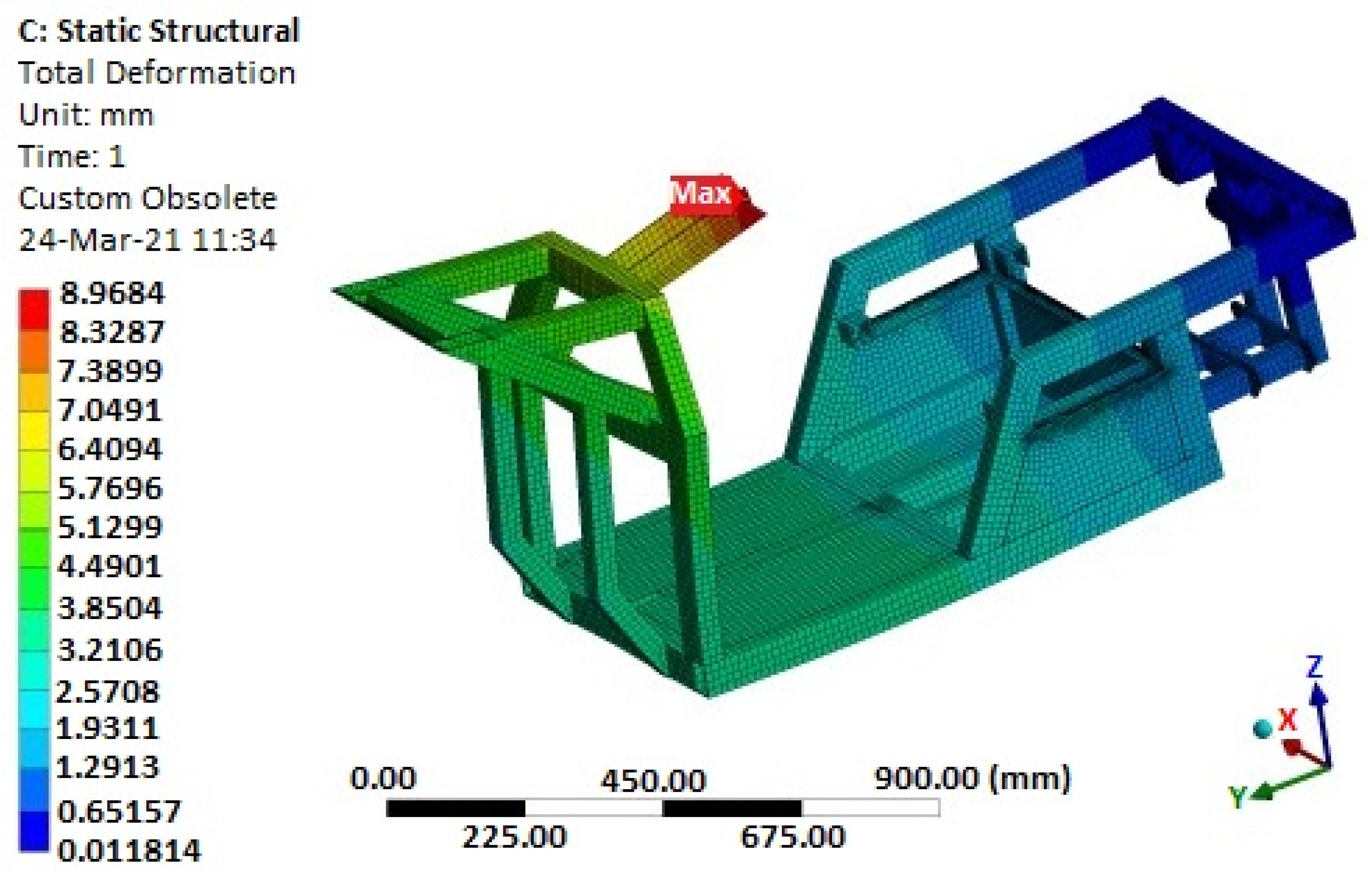
In terms of determining the stresses by means of static analysis, two limit states were considered. The first state (
Figure 12) simulated the calculation of the stresses of the E3-cycle frame at rest and in straight-line motion, respectively. In this case, the frame is not acted upon by centrifugal (transverse) forces arising from the motion of the body on the curved path. The loading forces resulted from the vehicle’s and rider’s own weights. The distribution of stresses in the frame for a freestanding vehicle was investigated. This calculation is only informative due to the fact that the highest stress achieved is essential. The highest stress will certainly be accomplished at the second limit state. The boundary conditions for the first limit state are defined in
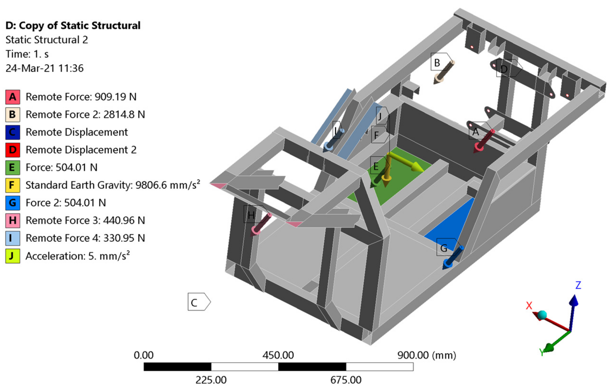
Figure 12 (mass of the electric motor 41.4 kg, mass of the control electronics 23 kg, mass of the batteries 23 kg, mass of the rider 130 kg, mass of the steering wheel and steering mechanism 15 kg, front axle load 20 kg, mass of the frame 29 kg).
The second limit state (
Figure 13) simulated the passage of the analyzed vehicle through a curve with the considered lateral acceleration reaching half the value of the gravitational acceleration
g. The loading forces were determined with regard to the limiting adhesion of the E3-cycle’s tires to the road. Accordingly, the presented boundary conditions correspond to the actual limit state of the vehicle in question.


