Article

Effect of Ti3SiC2 and Ti3AlC2 Particles on Microstructure and Wear Resistance of Microarc Oxidation Layers on TC4 Alloy

School of Materials Science and Engineering, Liaoning University of Technology, Jinzhou 121001, China
*
Author to whom correspondence should be addressed.
Materials 2022, 15(24), 9078; https://doi.org/10.3390/ma15249078
Submission received: 7 November 2022 / Revised: 6 December 2022 / Accepted: 8 December 2022 / Published: 19 December 2022
(This article belongs to the Special Issue Wear and Corrosion Resistance Technology of Thin Film Materials)

Abstract

:
Microarc oxidation (MAO) layers were prepared using 8g/L Na2SiO3 + 6g/L (NaPO3)6 + 4g/L Na2WO4 electrolyte with the addition of 2g/L Ti3SiC2/Ti3AlC2 particles under constant-current mode. The roughness, porosity, composition, surface/cross-sectional morphology, and frictional behavior of the prepared MAO layers were characterized by 3D real-color electron microscopy, scanning electron microscopy, X-ray energy spectrometry, X-ray diffractometry, and with a tribo-tester. The results showed that the addition of Ti3SiC2 and Ti3AlC2 to the electrolyte reduced the porosity of the prepared layers by 9% compared with that of the MAO layer without added particles. The addition of Ti3SiC2/Ti3AlC2 also reduced the friction coefficient and wear rate of the prepared layers by 35% compared with that of the MAO layer without added particles. It was found that the addition of Ti3AlC2 particles to the electrolyte resulted in the lowest porosity and the lowest wear volume.

1. Introduction

Titanium alloys have high specific strength, good corrosion resistance and biocompatibility, a low coefficient of thermal expansion, and are widely used in aerospace, marine, and biomedical materials, but their low hardness and poor wear resistance limit further applications [1,2,3]. The wear and corrosion resistance of titanium alloys can be improved by surface treatment techniques. Current surface techniques for improving titanium alloys include chemical plating, spraying, vapor deposition, laser remelting, microarc oxidation, etc. [4,5,6,7,8]. Microarc oxidation (MAO) is a surface treatment technique used for metals or alloys such as Al [9], Mg [10], and Ti [11]. Under high-voltage or high-current conditions in different electrolytes, the ceramic layers are grown in situ on the material surface under the action of thermochemistry, plasma chemistry, and electrochemistry [12,13]. The current research on microarc oxidation is mainly focused on adjusting the electrolyte, optimizing the electrical parameters, and post-treatment sealing holes to improve the material properties. In comparing the different electrolyte systems, researchers found that the MAO layer in the silicate electrolyte grew almost entirely outwards, which resulted in a porous coating and improved wear resistance. The inward growth of the MAO layer in the phosphate electrolyte resulted in a compact coating structure and high adhesion, but the wear resistance of the coating was poor [14]. At the same time, researchers have added additives such as sodium tungstate, sodium molybdate, CNTs, and rare earth salts to the electrolyte to improve the density of the film layer and have also changed electrical parameters such as the power mode, current density, frequency, and duty cycle to control the thickness and roughness of the MAO layer [15,16,17,18,19,20,21,22].
In recent years, many researchers have added insoluble nanoparticles of SiO2, ZrO2, SiC, TiO2, and Al2O3; graphite powder; graphene; and other compounds to the electrolyte to prepare microarc oxidation layers to improve wear resistance, thickness, and roughness, and reduce defects [23,24,25,26,27,28,29]. Ti3SiC2 and Ti3AlC2 have high melting points and good corrosion resistance as well as the high thermal and electrical conductivity of metals [30]. There are no studies on the addition of titanium–silicon–carbon to the electrolyte. In this study, we prepared microarc oxidation layers by adding Ti3SiC2/Ti3AlC2 conductive particles to the electrolyte and compared and analyzed the structure, composition, and wear resistance of the prepared layers.

2. Experiments and Characterization

2.1. Preparation and Experiments

The TC4 alloy rods were used to make specimens of size Φ25 × 3mm, which were then polished with 120#~800# sandpaper, cleaned with anhydrous ethanol ultrasonically, and blow-dried. The electrolyte was composed of a compound salt system (8g/L Na2SiO3 + 6g/L 6g/L (NaPO3)6 + 4g/L Na3WO4), and 2g/L Ti3SiC2/Ti3AlC2 was added to the electrolyte to make a suspension. The microarc oxidation process was conducted with a WHD-30D plasma microarc oxidation system with electrical parameters of a constant current of 11A/dm2, duty cycle of 50%, frequency of 500 HZ, and time of 15 min. Table 1 shows the information on the main experimental materials and reagents.

2.2. Analysis and Characterization

D/Max-2500 X-ray diffractometer was used to analyze the physical phase composition of the prepared layer (20°~90°, 6°/min); Axio Vert.A1 metallographic microscope and Zeiss SIGMA 500 scanning electron microscope were used to observe the cross section and surface morphology of the layer; a pin–disk friction and wear tester was used to conduct a dry sliding test on the MAO layer. SEM photographs of the surface of the MAO layer were analyzed using Image J software, and the original image threshold was adjusted to cover the pores. The percentage of area occupied by surface pores was calculated as the porosity of the oxide film using a software calculation tool [31,32]. Film thickness and wear volume were measured several times and averaged to ensure quality control.

3. Results and Discussion

3.1. Cross Section and Surface Topography

From Figure 1, it can be seen that the thickness of the MAO layer without the addition of particles is about 17~25 μm. The inner layer is dense, and the surface layer is loose. There are small micropores in its “honeycomb” structure and a few cracks in some areas. By adding the particles to the electrolytes, the thickness of the layer slightly increases, there are no large pores, and the density of the MAO layer is higher. As shown in Figure 2, the porosity of the MAO layer was obviously reduced after adding Ti3SiC2/Ti3AlC2. As shown in Figure 3, the thickness of the MAO layer after adding Ti3SiC2/Ti3AlC2 was less affected by the added particles, increasing by 1–2 μm, while the porosity decreased by about 46% after adding Ti3AlC2 particles compared with MAO. The reason for these two phenomena is that the addition of the MAO discharge stage produces a violent spark discharge temperature, which penetrates the MAO layer formed in the low-pressure stage and forms a discharge channel, from which molten metal oxides are ejected onto the surface of the MAO layer, and defects such as surface micropores and pits are formed through quenching, cooling, and curing of the electrolyte. Cracks are formed when the surface temperature is too high, and stress cracks appear during solidification when the subcooling degree is high. On one hand, the addition of Ti3SiC2/Ti3AlC2 to the electrolyte improves the conductivity and reduces the arc starting voltage of MAO. On the other hand, the high melting point of ceramic particles absorbs the heat generated by the discharge spark and produces a small amount of microporosity on the uniform surface [33,34].

3.2. X-ray Analysis

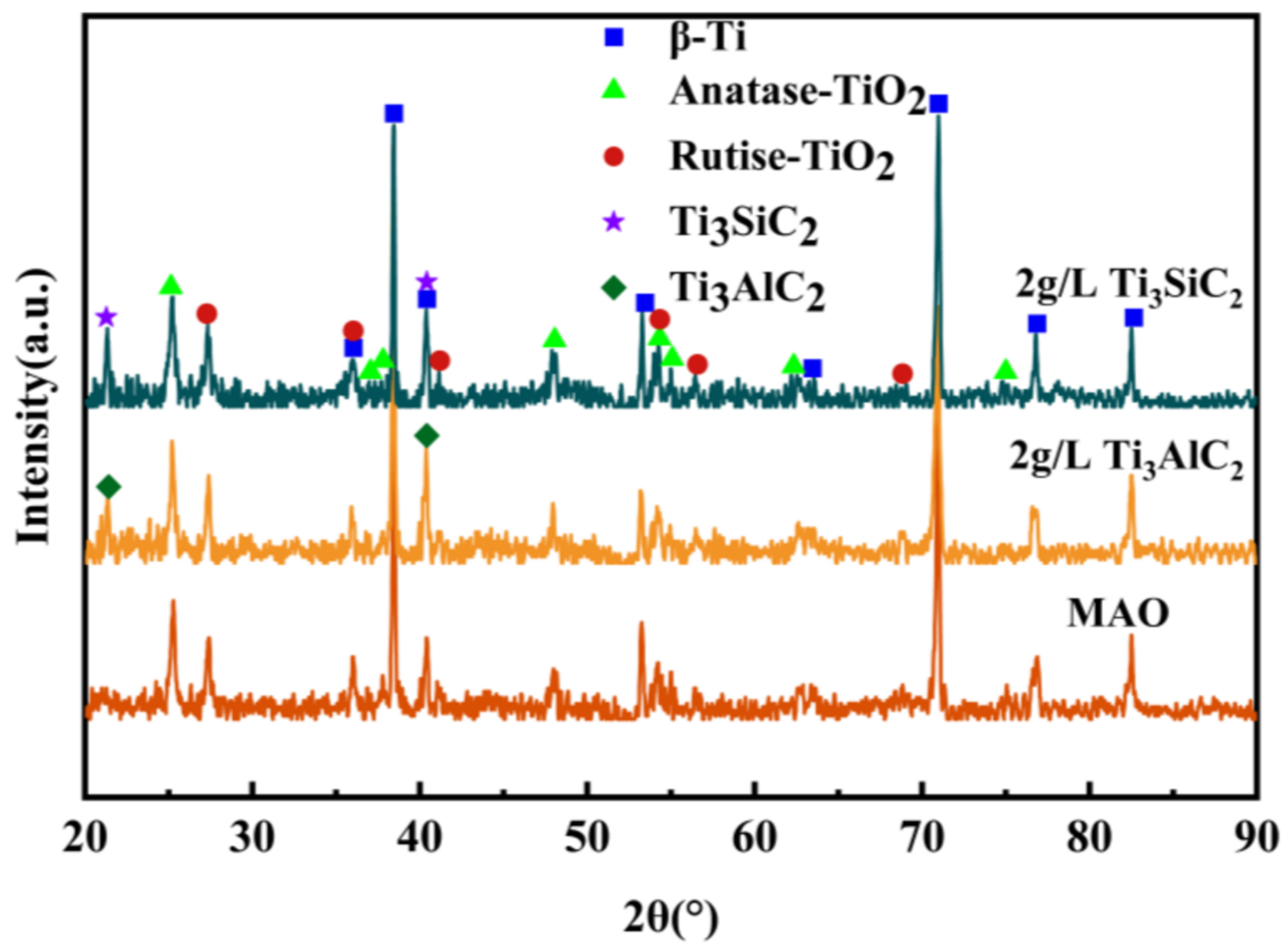
As can be seen from Figure 4, the MAO layer is mainly composed of anatase and rutile phases and a small amount of matrix and second-phase particles. It is shown that the high MAO surface temperature causes the molten oxidation of the matrix surface, and the TiO2 transforms from an indeterminate form to a substable anatase phase due to the slow atomic diffusion caused by the high subcooling, while the matrix surface temperature is higher and the substable crystallization forms the rutile phase [35]. The very high diffraction peaks of the TC4 matrix appear in the XRD pattern due to the loose structure of the surface layer, which is easier for the rays to penetrate, and the dense and more stable structure of the inner layer. The addition of Ti3SiC2/Ti3AlC2 did not change the phase composition of the MAO layer.

3.3. Friction and Wear Experiment

From Figure 5a, it can be seen that the friction coefficient gradually increases from low to high with the increase in friction time. This is due to the sparse surface structure of the MAO layer, its roughness, and its low hardness. The friction coefficient is low at the beginning of the friction; with the increase in friction time, the particles fill the micropores and then the actual contact surface of the dense structure. The friction coefficient gradually increased, and then tended to stabilize and then fluctuate. The friction coefficient curve after the addition of the particles all decreased. From Figure 5b, it can be seen that the average friction coefficient decreased with Ti3SiC2/Ti3AlC2 particle addition, and wear volume decreased from 0.92 mm3 to 0.59 mm3. From Figure 6, it can be seen that after sliding friction, the abrasion marks obtained are deep and there are a lot of deep grooves and protrusions on the rough surface of the abrasion marks (Figure 5a), while after the addition of Ti3SiC2/Ti3AlC2 particles, the abrasion marks of the layer are smooth and shallow. The addition of Ti3SiC2/Ti3AlC2 particles to the prepared layer can reduce wear volume. This wear reduction is because of the Ti3SiC2/Ti3AlC2 particles in the MAO layer that provide self-lubrication during the frictional wear process [36].
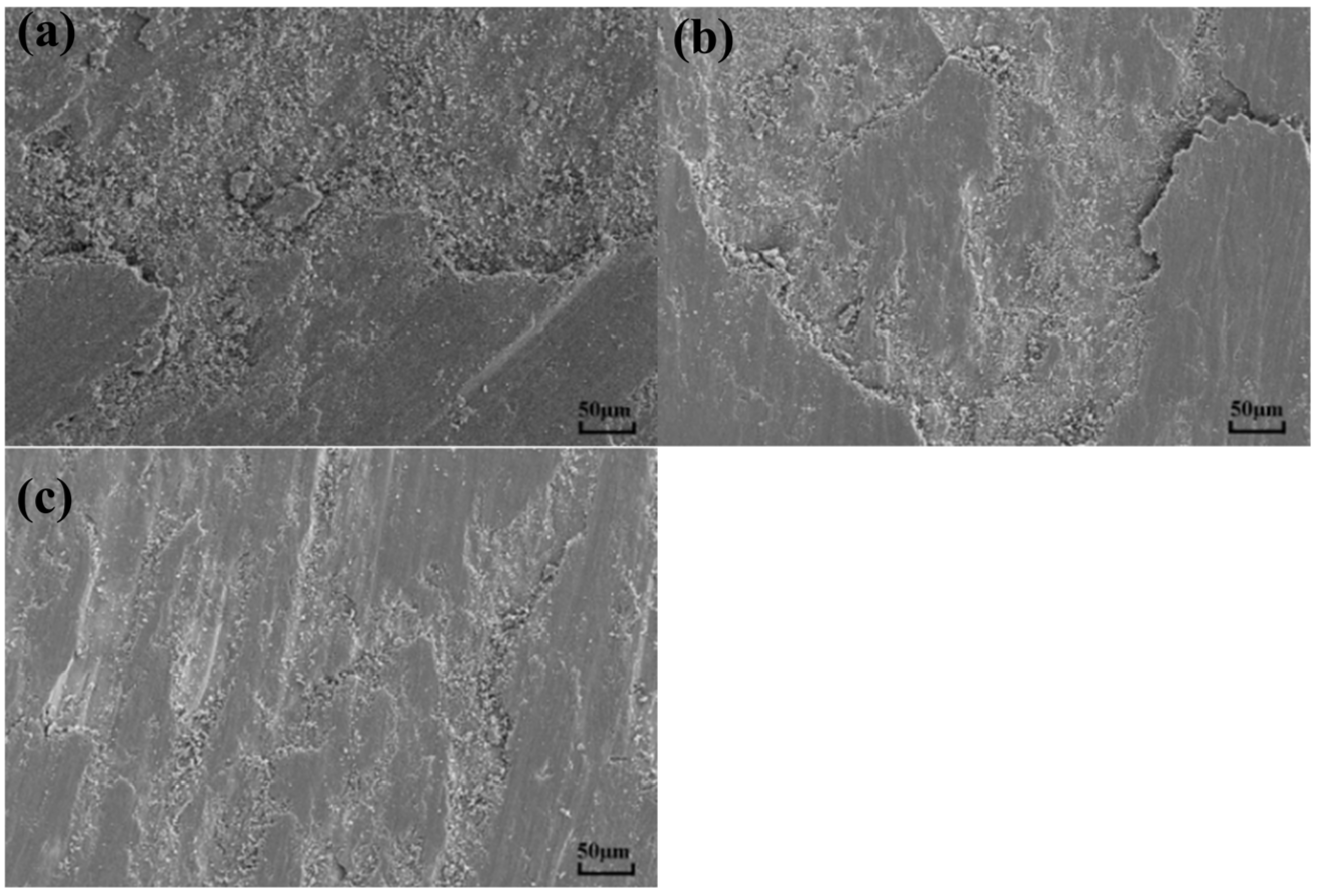
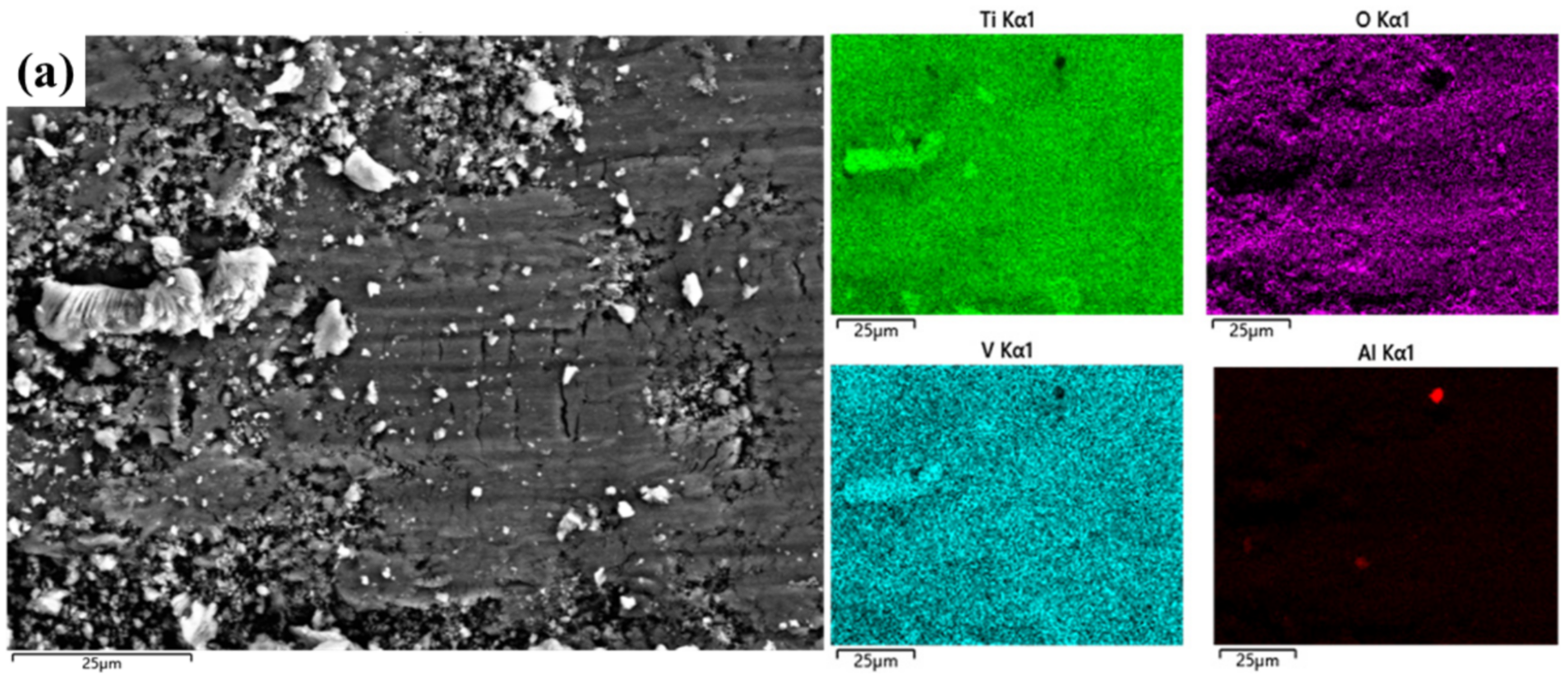
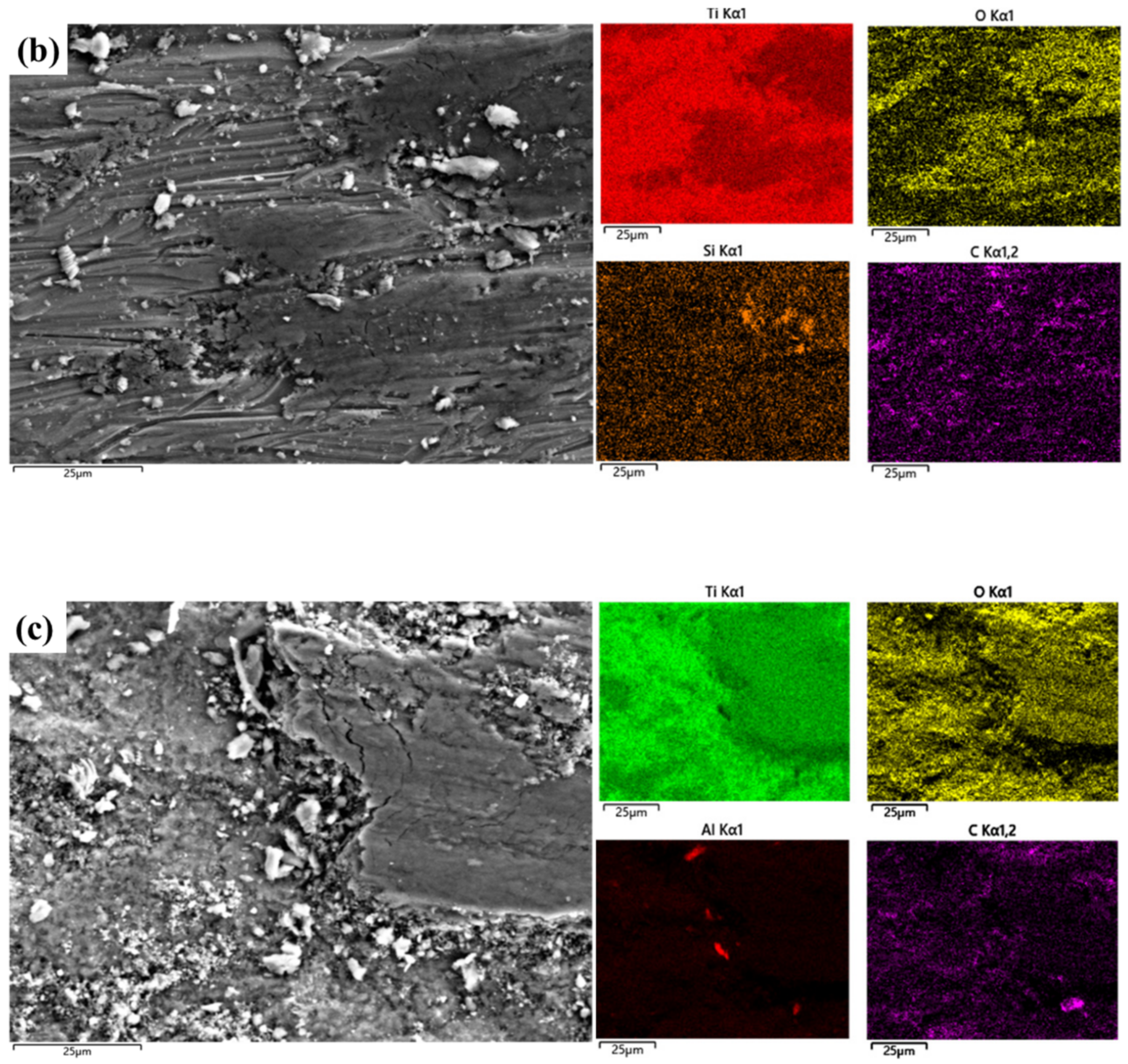
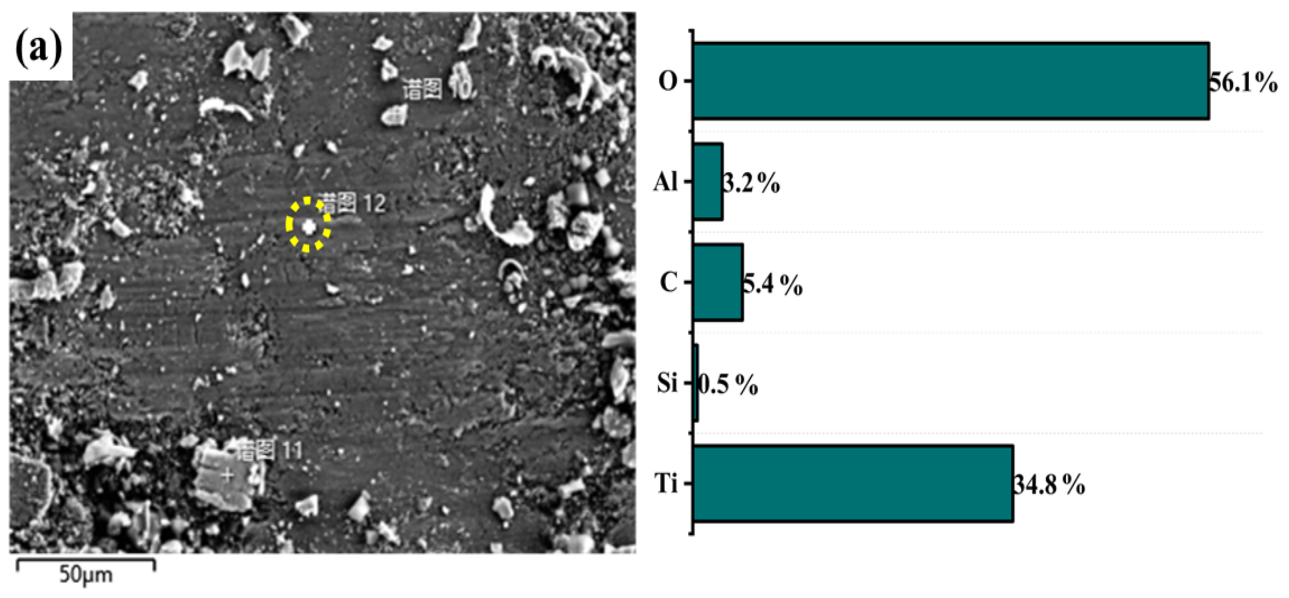
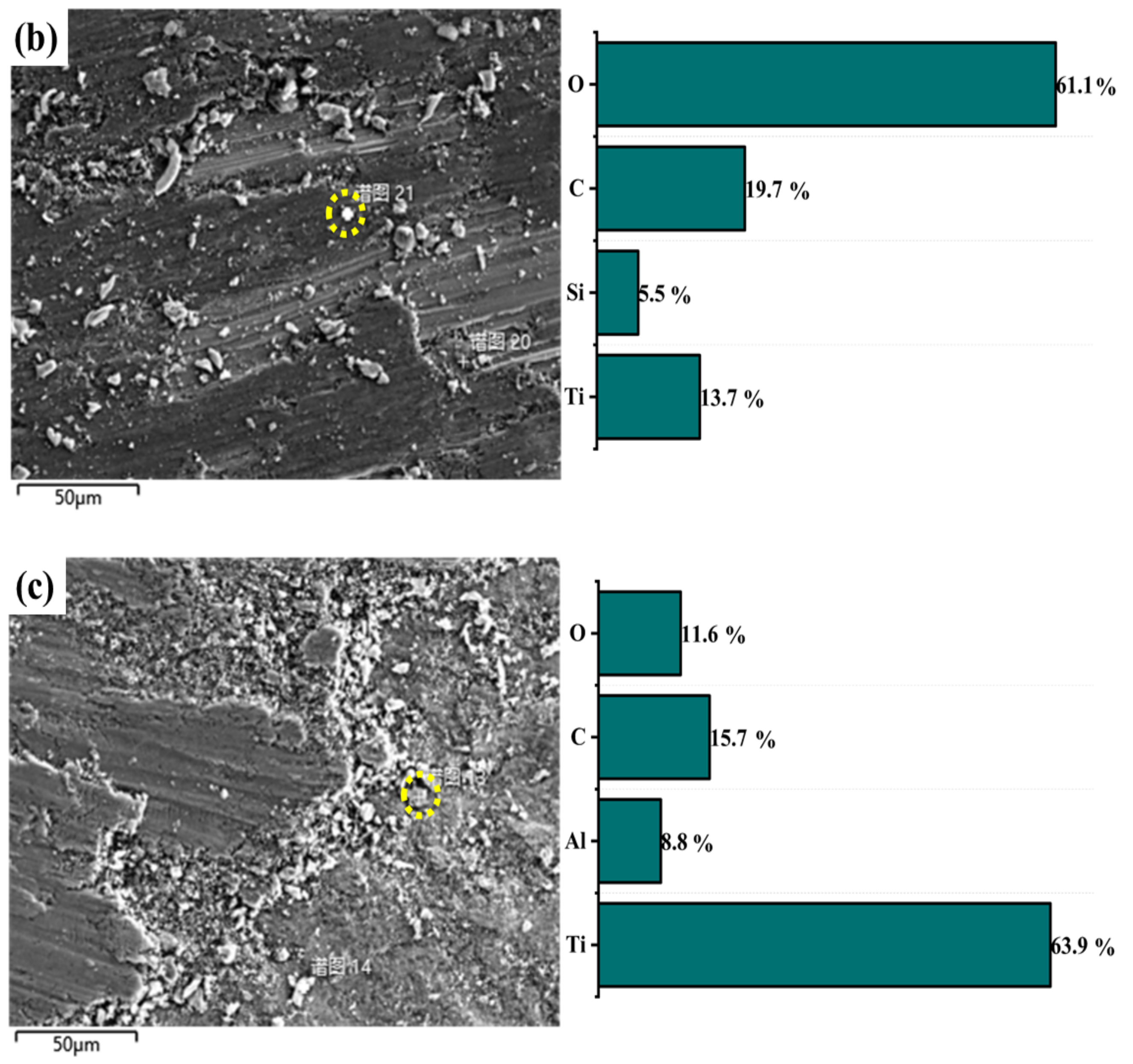
Figure 7a shows that there are many abrasive particles and large grains in the abrasion marks of the MAO layer without added particles. Transverse cracks appear in the grooves and the wear mechanism is abrasive wear. From Figure 7b, it can be seen that the surface of the abrasion marks of the MAO layer with Ti3SiC2 particles appears to be delaminated. This is due to the large difference in hardness between the dense layer and the substrate and the stress concentration of the flaky abrasive particles during wear. The wear surface of the MAO layer containing Ti3AlC2 ceramic particles is smooth, and the wear depth is shallow, as seen in Figure 7c. The improved wear marks are attributed to the lubricity properties of the particles and the improved quality of the MAO layer. An EDS surface scan of the wear marks was carried out. The elemental composition of the wear marks changed significantly after the particles were found. As shown in Figure 8a, only a large amount of Ti and O and a small amount of matrix elements such as Al and V are present in the wear marks of the MAO layer. In (b,c), a certain amount of Si appears, and the content of Al increases in (c). This can be seen in the energy spectrum dot scan at the yellow circle mark in Figure 9; in the MAO grinding without added particles, the particles in the grinding marks are 90% Ti and O. This means that the main component is TiO2. However, the addition of Ti3SiC2 in Figure 9b results in a significant increase in Si and C, indicating the presence of Ti3SiC2, with SiO2 in the particles. The increase in Al and C in Figure 9c indicates the presence of Ti3AlC2 as well as Al2O3. This is also consistent with the findings of the surface scan in Figure 6. The presence of small amounts of Ti3SiC2/Ti3AlC2 on the wear marks can be attributed to two factors: the original particles involved in the growth of the wear marks, and the shallow particles carried by the grinding ball as it was worn during the grinding process. However, the abrasion marks penetrate deep into the matrix and only a few Ti3SiC2/Ti3AlC2 particles are attached to the abrasion marks. This suggests that the Ti3SiC2/Ti3AlC2 present in the MAO layer is involved in the wear process and does have a positive effect on the wear resistance.

3.4. Wear Mechanisms

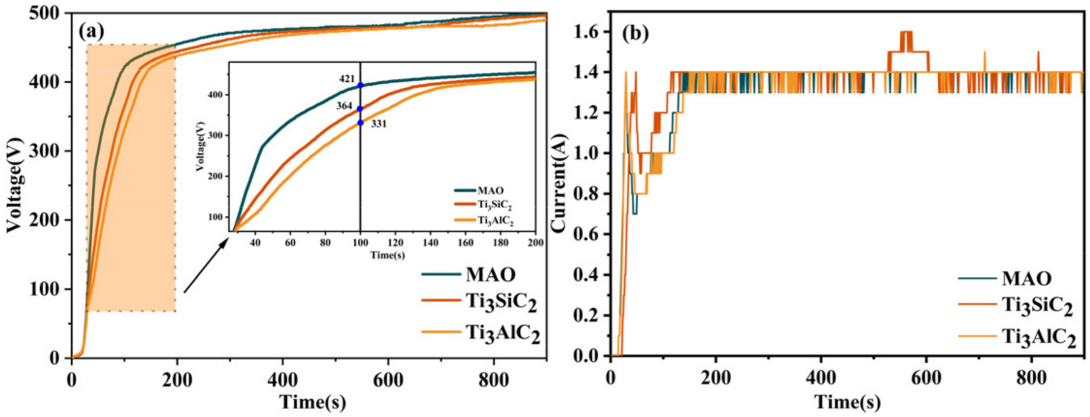
The effect on the layer thickness and porosity is mainly due to two factors: Firstly, Ti3SiC2/Ti3AlC2 are deposited directly on the layer and have a “sealing effect”. Secondly, Ti3SiC2/Ti3AlC2 increase the electrical conductivity of the electrolyte, which affects the voltage during MAO. As can be seen in Figure 9, no significant difference appears in the first 30s of MAO, and after 30s the voltage of MAO without added particles is significantly higher than the other two layers. At this point, the low voltage means low energy density, which also leads to low damage to the film layer and ultimately to a significant increase in MAO layer density. In Figure 10b, it can be seen that during the first 200S of the microarc oxidation process there is a certain difference in current: the addition of Ti3SiC2/Ti3AlC2 causes an extremely higher current curve, corresponding to a lower voltage at this stage than without the addition of these particles, which again proves that Ti3SiC2/Ti3AlC2 increase the electrical conductivity of the solution. In the subsequent stages, the addition of pellets did not have a significant effect on the current profile of the microarc oxidation process due to the constant-current mode.
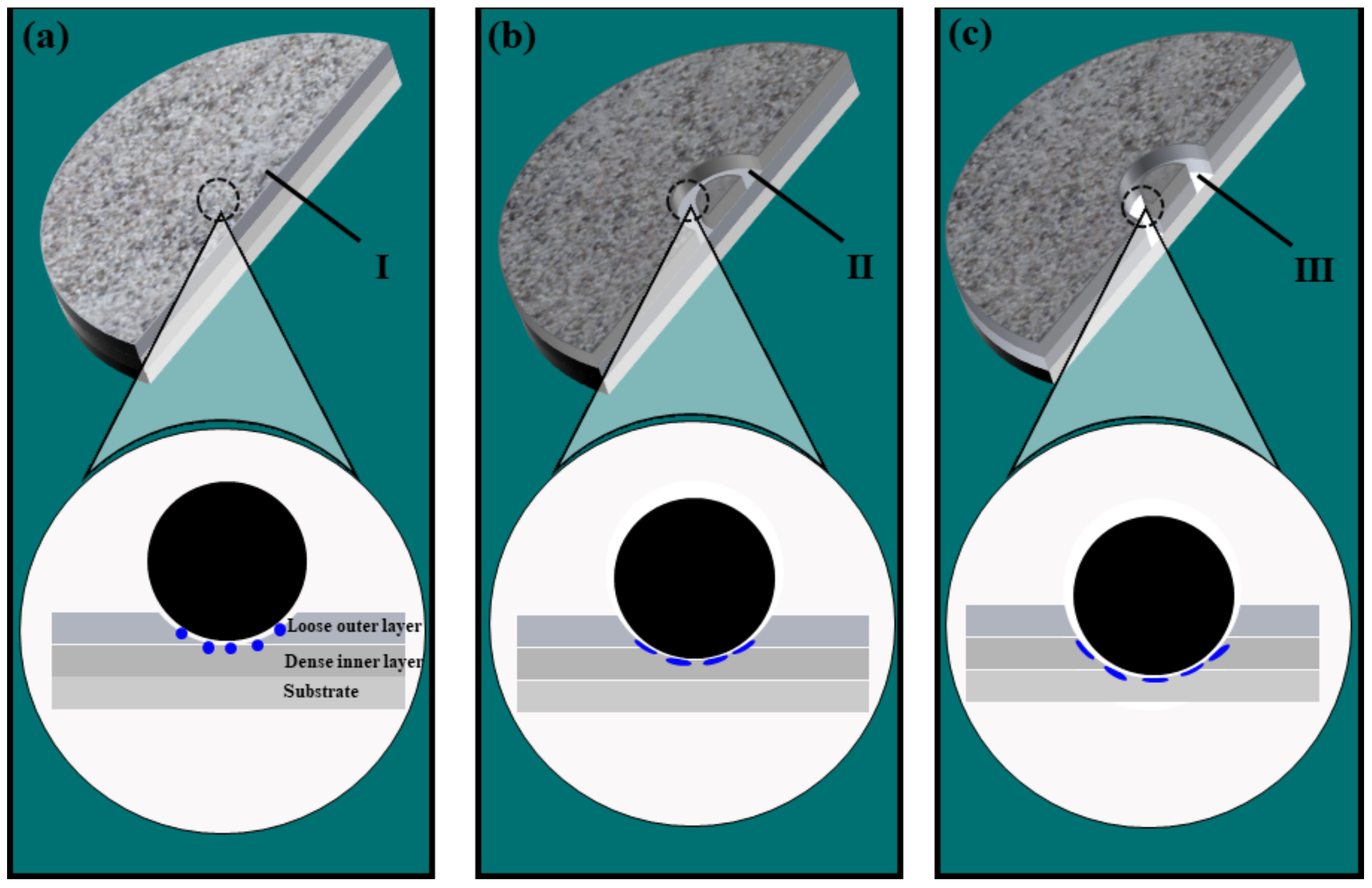
The effect of Ti3SiC2/Ti3AlC2 on wear resistance is divided into three stages, as shown in Figure 11: (a) The first stage, when the sparse surface oxide layer is in contact with the abrasive ball and the change in the surface quality of the film does not significantly improve the average coefficient of friction. (b) The second stage, when the sparse surface layer of microarc oxidation has been worn through. From the first to the second stage, the pores of the sparse oxide layer and the Ti3SiC2/Ti3AlC2 in the film gradually start to influence the friction process. (c) The third stage, when the MAO layer is worn through, and a certain amount of the titanium alloy matrix is exposed. Ti3SiC2/Ti3AlC2 play two main roles in the process from the second to the third stage. As particles in a laminar structure, they have good self-lubricating properties, so a certain amount of Ti3SiC2/Ti3AlC2 is concentrated to form a lubricating layer under the high-temperature and high-pressure conditions of the grinding ball friction process. The friction coefficient of the film layer is reduced. On the other hand, the added particles decompose and oxidize during the friction process, forming hard phases such as SiO2 and Al2O3, which increase the hardness of the MAO layer. It can be concluded that the first to second stage corresponds to the period before 4 min in Figure 5, when the Ti3SiC2/Ti3AlC2 particles have not yet had sufficient influence so that there is no significant difference in the friction coefficient curve, and the second to third stage corresponds to the period after 4 min in Figure 5, when the friction coefficient curve under the Ti3SiC2/Ti3AlC2 particles slowly decreases and fluctuates under the influence of the particles. The friction coefficient of the MAO layer with the added particles at this stage is low, wear is low, and the wear resistance of the MAO layer is improved.
In conclusion, the addition of Ti3SiC2/Ti3AlC2 have a positive effect on the thickness, porosity, and wear resistance of the MAO layer.

4. Conclusions

The MAO layers prepared by adding Ti3SiC2 and Ti3AlC2 particles to the electrolyte are thicker than those without added particles. The thickest MAO layer with the addition of Ti3SiC2 particles is 21.42 μm, and the lowest surface porosity with the addition of Ti3AlC2 is 46% lower that of the MAO layer without added particles. The addition of Ti3AlC2 particles to the electrolyte reduces the coefficient of friction and improves wear resistance. The layer prepared by adding Ti3AlC2 particles to the electrolyte has an average friction coefficient of 0.37 and a wear volume of 0.5939 mm3, which is 35% less than that of the MAO layer without added particles. It is clear that the addition of Ti3AlC2 to the electrolyte has a positive effect on the thickness, porosity, and wear resistance of the MAO layer.

Author Contributions

Writing—original draft, G.G.; Writing—review & editing, J.S.; Supervision, D.L. All authors have read and agreed to the published version of the manuscript.

Funding

This research was funded by the Liaoning Provincial Department of Science and Technology Mentoring Program Project (2019-ZD-0703).

Institutional Review Board Statement

Not applicable.

Informed Consent Statement

Not applicable.

Data Availability Statement

Not applicable.

Conflicts of Interest

The authors declare no conflict of interest.

References

  1. Korkmaz, K. The effect of Micro-arc Oxidation treatment on the microstructure and properties of open cell Ti–6Al–4V alloy foams. Surf. Coat. Technol. 2015, 272, 72–78. [Google Scholar] [CrossRef]
  2. Wang, Y.-M.; Zou, Y.-C.; Wang, S.-Q. Fabrication and Performance of Multifuctional Ceramic Coatings Formed by Microarc Oxidation on Metals: A Critial Review. China Surf. Eng. 2018, 31, 20–45. [Google Scholar]
  3. Jin, H.-X.; Wei, K.-X.; Li, J.-M. Progress in research on titanium alloys for aviation. Chin. J. Nonferrous Met. 2015, 25, 280–292. [Google Scholar]
  4. Fu, C.; Weng, S.; Fan, J. Boron-based materials modified on the surface of TiO2 nanorods via electroless plating toward high-efficient solar-driven water splitting. Chem. Eng. J. 2022, 430, 132881. [Google Scholar] [CrossRef]
  5. Feng, J.; Wang, J.; Yang, K. Microstructure and performance of YTaO4 coating deposited by atmospheric plasma spraying on TC4 titanium alloy surface. Surf. Coat. Technol. 2022, 431, 128004. [Google Scholar] [CrossRef]
  6. Yumusak, G.; Leyland, A.; Matthews, A. A microabrasion wear study of nitrided α-Ti and β-TiNb PVD metallic thin films, pre-deposited onto titanium alloy substrates. Surf. Coat. Technol. 2022, 442, 128423. [Google Scholar] [CrossRef]
  7. Grabowski, A.; Florian, T.; Wieczorek, J.; Adamiak, M. Structuring of the Ti6Al4V alloy surface by pulsed laser remelting. Appl. Surf. Sci. 2021, 535, 147618. [Google Scholar] [CrossRef]
  8. Liao, S.-C.; Chang, C.-T.; Chen, C.-Y. Functionalization of pure titanium MAO coatings by surface modifications for biomedical applications. Surf. Coat. Technol. 2020, 394, 125812. [Google Scholar] [CrossRef]
  9. Bisztyga-Szklarz, M.; Rząd, E.; Boroń, Ł.; Klimczyk, P.; Polczyk, T.; Łętocha, A.; Rajska, M.; Hebda, M.; Długosz, P. Properties of Microplasma Coating on AZ91 Magnesium Alloy Prepared from Electrolyte with and without the Borax Addition. Materials 2022, 15, 1354. [Google Scholar] [CrossRef]
  10. Schwartz, A.; Kossenko, A.; Zinigrad, M.; Gofer, Y.; Borodianskiy, K.; Sobolev, A. Hydroxyapatite Coating on Ti-6Al-7Nb Alloy by Plasma Electrolytic Oxidation in Salt-Based Electrolyte. Materials 2022, 15, 7374. [Google Scholar] [CrossRef]
  11. Yao, Z.; Jiang, Y.; Jia, F. Growth Characteristics of Plasma Electrolytic Oxidation Ceramic coatings On Ti–6Al–4V Alloy. Appl. Surf. Sci. 2008, 254, 4084–4091. [Google Scholar] [CrossRef]
  12. Gao, G.-R.; Li, Z.-X.; Du, J.-H. Study of the corrosion resistance and friction properties of TC4 alloy surface micro-arc oxide film. Rare Met. Mater. Eng. 2008, 37, 602–605. [Google Scholar]
  13. Sun, C.; Hui, R.; Qu, W. Effects of processing parameters on microstructures of TiO2 coatings formed on titanium by plasma electrolytic oxidation. J. Mater. Sci. 2010, 45, 6235–6241. [Google Scholar] [CrossRef]
  14. Li, Q.-B.; Yang, W.-B.; Liu, C.-C.; Wang, D.-A.; Liang, J. Correlations between the growth mechanism and properties of micro-arc oxidation coatings on titanium alloy: Effects of electrolytes. Surf. Coat. Technol. 2017, 316, 162–170. [Google Scholar] [CrossRef]
  15. Liu, H.-H.; Wang, S.-X.; Liu, X.-H.; Zhao, Q.; Yu, L.-X.; Gao, A.; Zhong, H. Optimisation of Ti2AlNb alloy micro-arc oxidation electrolyte and study of wear resistance. Surf. Technol. 2018, 47, 85–91. [Google Scholar]
  16. Chen, X.-X.; Liao, D.-D.; Chen, W.-X.; Cai, L.-P.; Zhao, P.-C.; Jiang, H.; Shi, T.-H. Effect of sodium tungstate addition on the wear resistance of micro-arc oxide layer of titanium alloy drill pipe. Mater. Prot. 2019, 52, 90–94+107. [Google Scholar]
  17. Guo, Y.-F.; Xu, L.-Y.; Luan, J.-J.; Wan, Y.; Li, R.-C. Effect of carbon nanotubes additive on tribocorrosion performance of micro-arc oxidized coatings on Ti6Al4V alloy. Surf. Interfaces 2022, 28, 101626. [Google Scholar] [CrossRef]
  18. Di, S.-C.; Guo, Y.-P.; Lv, H.-W.; Yu, J.; Li, Z.-W. Microstructure and properties of rare earth CeO2-doped TiO2 nanostructured composite coatings through micro-arc oxidation. Ceram. Int. 2015, 41, 6178–6186. [Google Scholar] [CrossRef]
  19. Terleeva, O.-P.; Sharkeev, Y.-P.; Slonova, A.-I. Effect of microplasma modes and electrolyte composition on micro-arc oxidation coatings on titanium for medical applications. Surf. Coat. Technol. 2010, 205, 1723–1729. [Google Scholar] [CrossRef]
  20. Yue, Y.-J.; Wu, H. Effects of Current Density on Microstructure of Titania Coatings by Micro-arc Oxidation. J. Mater. Sci. Technol. 2012, 28, 321–324. [Google Scholar]
  21. Sobolev, A.; Kossenko, A.; Borodianskiy, K. Study of the effect of current pulse frequency on Ti6Al4V alloy coating formation by micro arc oxidation. Materials 2019, 12, 3983. [Google Scholar] [CrossRef] [PubMed] [Green Version]
  22. Yang, M.; Huang, T.; Wang, D. Effects of duty ratio on properties of micro-arc film on Ti3Zr2Sn3Mo25Nb. Trans. IMF 2018, 96, 269–274. [Google Scholar] [CrossRef]
  23. Li, H.; Sun, Y.; Zhang, J. Effect of ZrO2 particle on the performance of micro-arc oxidation coatings on Ti6Al4V. Appl. Surf. Sci. 2015, 324, 183–190. [Google Scholar] [CrossRef]
  24. Mu, M.; Liang, J.; Zhou, X. One-step preparation of TiO2/MoS2 composite coating on Ti6Al4V alloy by plasma electrolytic oxidation and its tribological properties. Surf. Coat. Technol. 2013, 214, 124–130. [Google Scholar] [CrossRef]
  25. Zhao, J.; Xie, X.; Zhang, C. Effect of the graphene oxide additive on the corrosion resistance of the plasma electrolytic oxidation coating of the AZ31 magnesium alloy. Corros. Sci. 2017, 114, 146–155. [Google Scholar] [CrossRef]
  26. Zhang, X.-L.; Jiang, Z.-H.; Yao, Z.-P. Electrochemical study of growth behaviour of plasma electrolytic oxidation coating on Ti6Al4V: Effects of the additive. Corros. Sci. 2010, 52, 3465–3473. [Google Scholar] [CrossRef]
  27. Wang, Y.-Q.; Zheng, M.-Y.; Wu, K. Microarc oxidation coating formed on SiCw/AZ91 magnesium matrix composite and its corrosion resistance. Mater. Lett. 2005, 59, 1727–1731. [Google Scholar] [CrossRef]
  28. Li, H.-Z.; Ma, Y.-P.; Li, Z.-X. Effect of graphite content on the micro-arc oxide film of TC4 titanium alloy. Titan. Ind. Prog. 2017, 34, 26–29. [Google Scholar]
  29. Zhang, Q.; Li, Y.-H.; Liu, X. TC4 Properties of ZrO2/TiO2 composite ceramic films on the surface of titanium alloys. Trans. Mater. Heat Treat. 2014, 9, 199–204. [Google Scholar]
  30. Zhai, W.; Lu, W.; Zhang, P. Wear-triggered self-healing behavior on the surface of nanocrystalline nickel aluminum bronze/Ti3SiC2 composites. Appl. Surf. Sci. 2018, 436, 1038–1049. [Google Scholar] [CrossRef]
  31. Dong, H.-R.; Ma, Y.; Guo, H.-X.; Zhang, Y.-F.; Hao, Y. Denseness of AZ91D magnesium alloy micro-arc oxide films and its effect on corrosion resistance. Trans. Nonferrous Met. Soc. China 2015, 25, 844–851. [Google Scholar]
  32. Nie, H.-C. Study on The Influence of Solution Components and Sealing Process on The Insulation Properties of Aluminium Alloy Micro Lone Oxide Layer; Xi’an University of Technology: Xi’an, China, 2017. [Google Scholar]
  33. Hu, Z.-C.; Xie, F.-Q.; Wu, X.-Q. Effects of Voltage on the Characteristics and Corrosion Resistance of Microarc Oxidation Coatings on Ti6Al4V Alloy. Adv. Mat. Res. 2010, 97, 1336–1339. [Google Scholar] [CrossRef]
  34. Li, B.-J.; Zhao, H.; Wang, X.-H.; Zhu, Q.-Z. Effect of electrical parameters on the micro-arc oxidation ceramic film of TC4 titanium alloy. J. Shenyang Univ. Technol. 2011, 30, 59–61. [Google Scholar]
  35. Qi, Y.-M.; Peng, Z.-J.; Liu, B.-X. Preparation of high hardness micro-arc oxide films on alloy surfaces and study of wear resistance. Surf. Technol. 2019, 48, 81–88. [Google Scholar]
  36. Pezzato, L.; Brunelli, K.; Dabala, M. Corrosion properties of plasma electrolytic oxidation coated AA7075 treated using an electrolyte containing lanthanum-salts. Surf. Interface. Anal. 2016, 48, 729–738. [Google Scholar] [CrossRef]
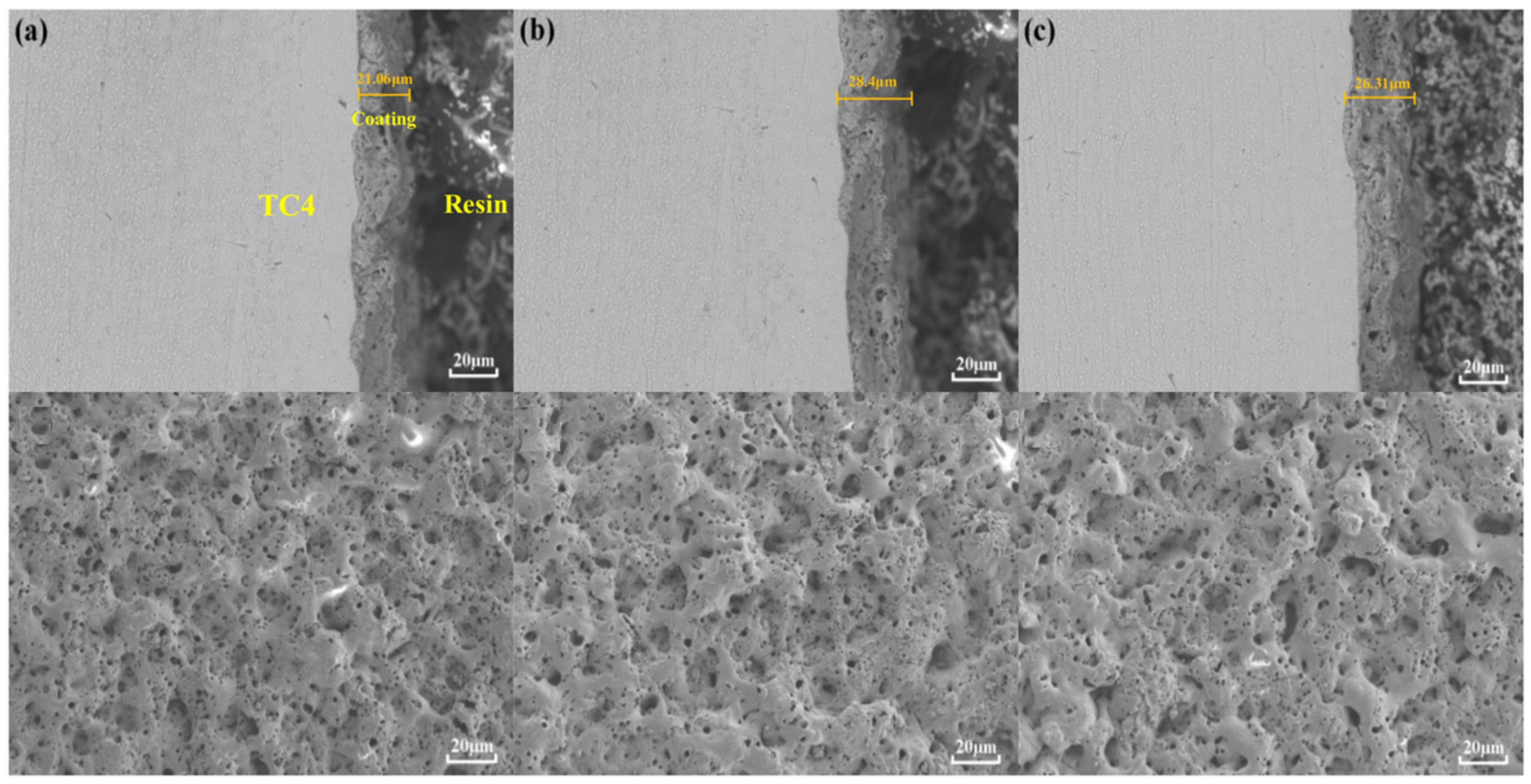
Figure 1. Cross-sectional and surface morphology of MAO layer on TC4 alloy with different additives: (a) MAO, (b) Ti3SiC2, (c) Ti3AlC2.
Materials 15 09078 g001
Figure 2. Surface porosity of MAO layers on TC4 alloy with different additives (pores marked in black): (a) MAO, (b) Ti3SiC2, (c) Ti3AlC2.
Materials 15 09078 g002
Figure 3. Surface porosity and average MAO layer thickness on TC4 alloys with different particle additions.
Materials 15 09078 g003
Figure 4. X-ray diffraction patterns of MAO layer on TC4 alloy with different particle additions.
Materials 15 09078 g004
Figure 5. Results of (a) dynamic friction coefficient and (b) average friction coefficient and wear volume loss of MAO layer onTC4 alloy with different particle additions.
Materials 15 09078 g005
Figure 6. Cross-sectional morphology of MAO layers on TC4 alloys with different particle additions. (a) MAO, (b) Ti3SiC2, (c) Ti3AlC2.
Materials 15 09078 g006
Figure 7. Worn morphology of MAO layer on TC4 alloy with different particle additions: (a) MAO, (b) Ti3SiC2, (c) Ti3AlC2.
Materials 15 09078 g007
Figure 8. EDS of MAO layer on TC4 alloy with different particle additions: (a) MAO, (b) Ti3SiC2, (c) Ti3AlC2.
Materials 15 09078 g008aMaterials 15 09078 g008b
Figure 9. EDS results of worn surface with different particles: (a) MAO, (b) Ti2SiC3, (c) Ti2AlC3.
Materials 15 09078 g009aMaterials 15 09078 g009b
Figure 10. Voltage vs. current curves for MAO layers on TC4 alloys with different particle additions. (a) Voltage curve. (b) Current curve.
Materials 15 09078 g010
Figure 11. Wear mechanism diagram of prepared layer with Ti3SiC2 and Ti3AlC2 particles addition. (a) Friction Stage 1. (b) Friction Stage 2. (c) Friction Stage 3. I Loose outer layer. II Dense inner layer. III Substrate.
Materials 15 09078 g011
Table 1. Experimental reagents and materials.
NameFormulaPurity ManufacturerCountry
TC4-HuiJing Metal Materials LimitedChina
Na2SiO3ARSinopharm Chemical Reagent Co.China
Na3PO4ARSinopharm Chemical Reagent Co.China
Na2WO4ARSinopharm Chemical Reagent Co.China
Ti3SiC298%ForsmanChina
Ti3AlC298%ForsmanChina
Publisher’s Note: MDPI stays neutral with regard to jurisdictional claims in published maps and institutional affiliations.