
Effect of Holding Time on the Extrusion Force and Microstructure Evolution during the Plastic Forming of Ti-6Al-4V Micro-Gears

Abstract
:1. Introduction
2. Materials and Methods
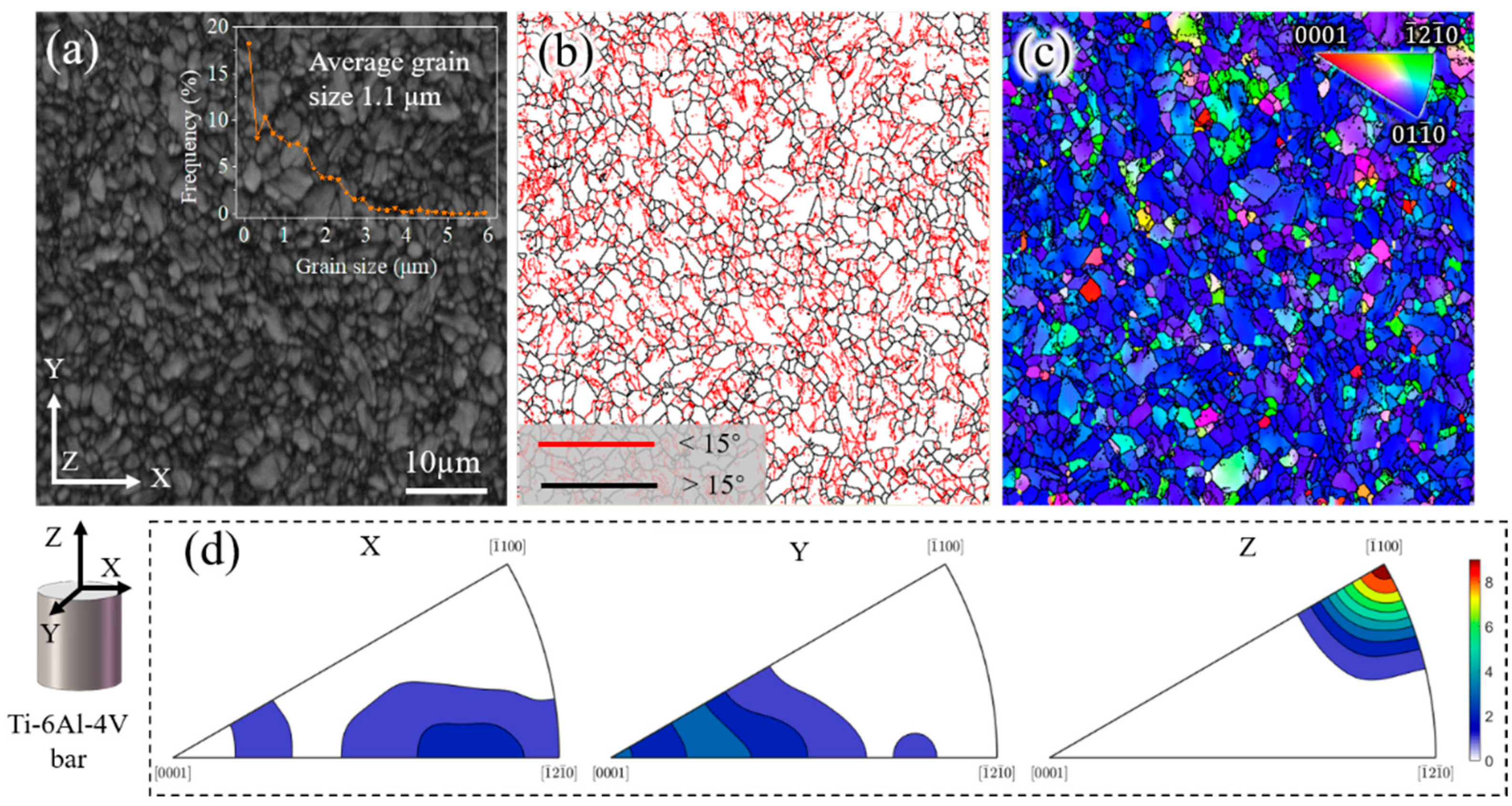
2.1. Materials
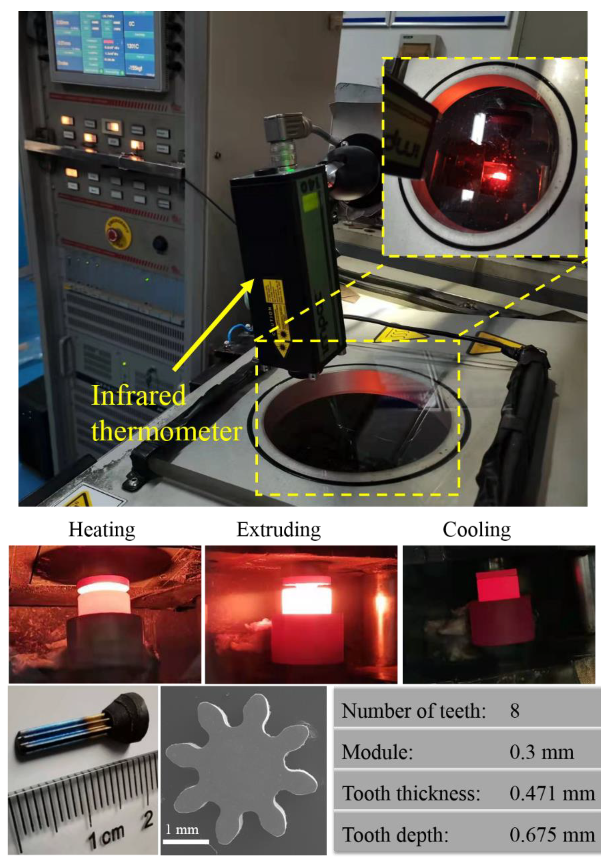
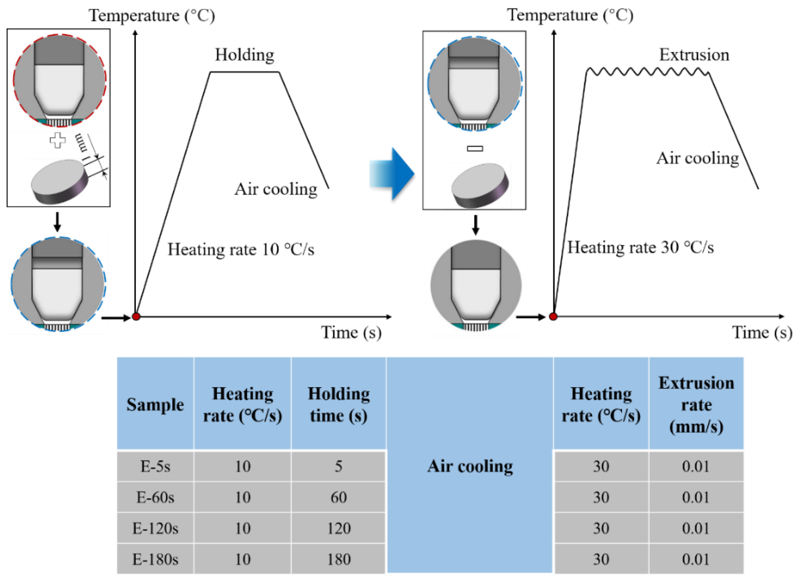
2.2. Methods
2.3. Characterization
3. Results and Discussion
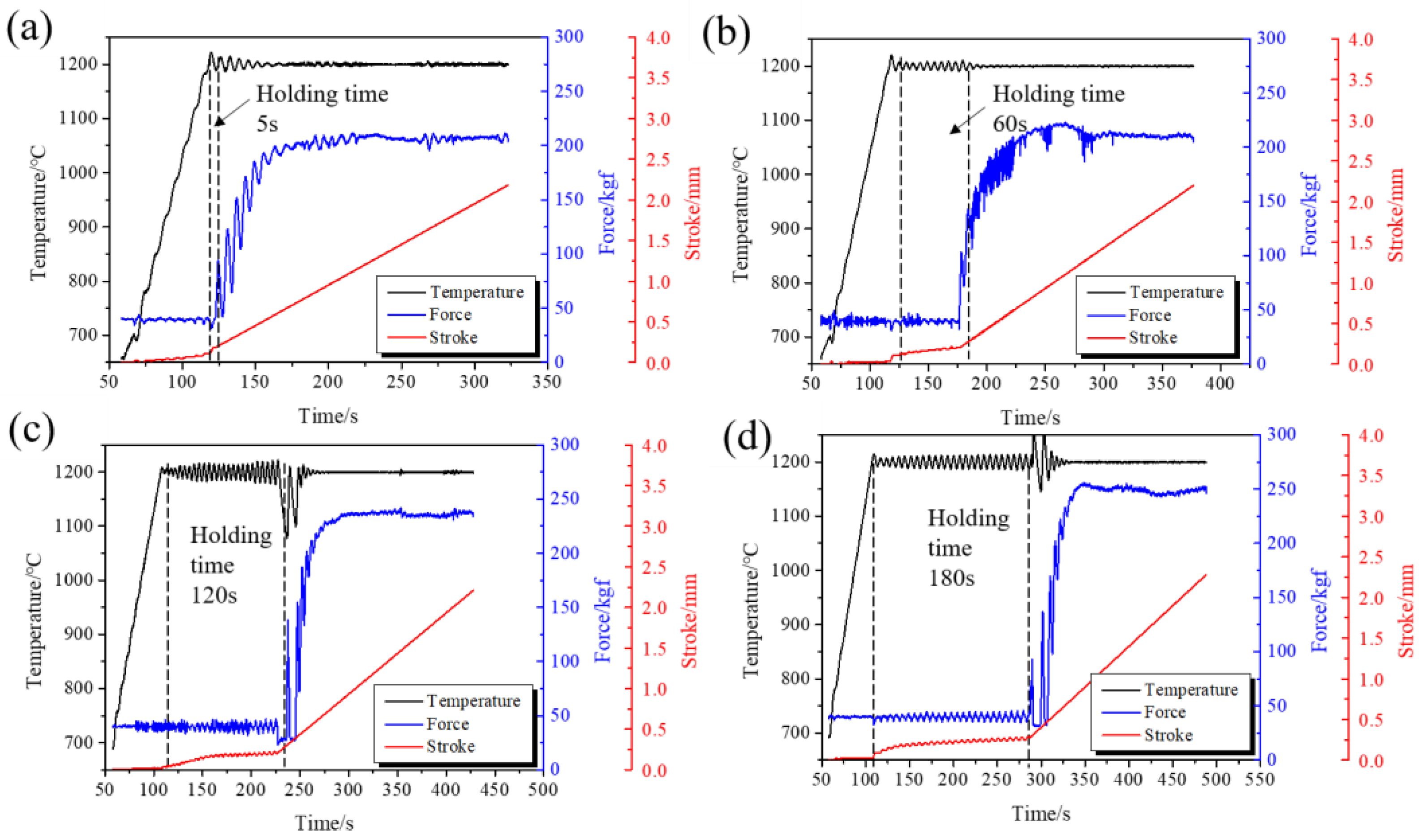
3.1. Formed Micro-Gear and Extrusion Force of Different Holding Times
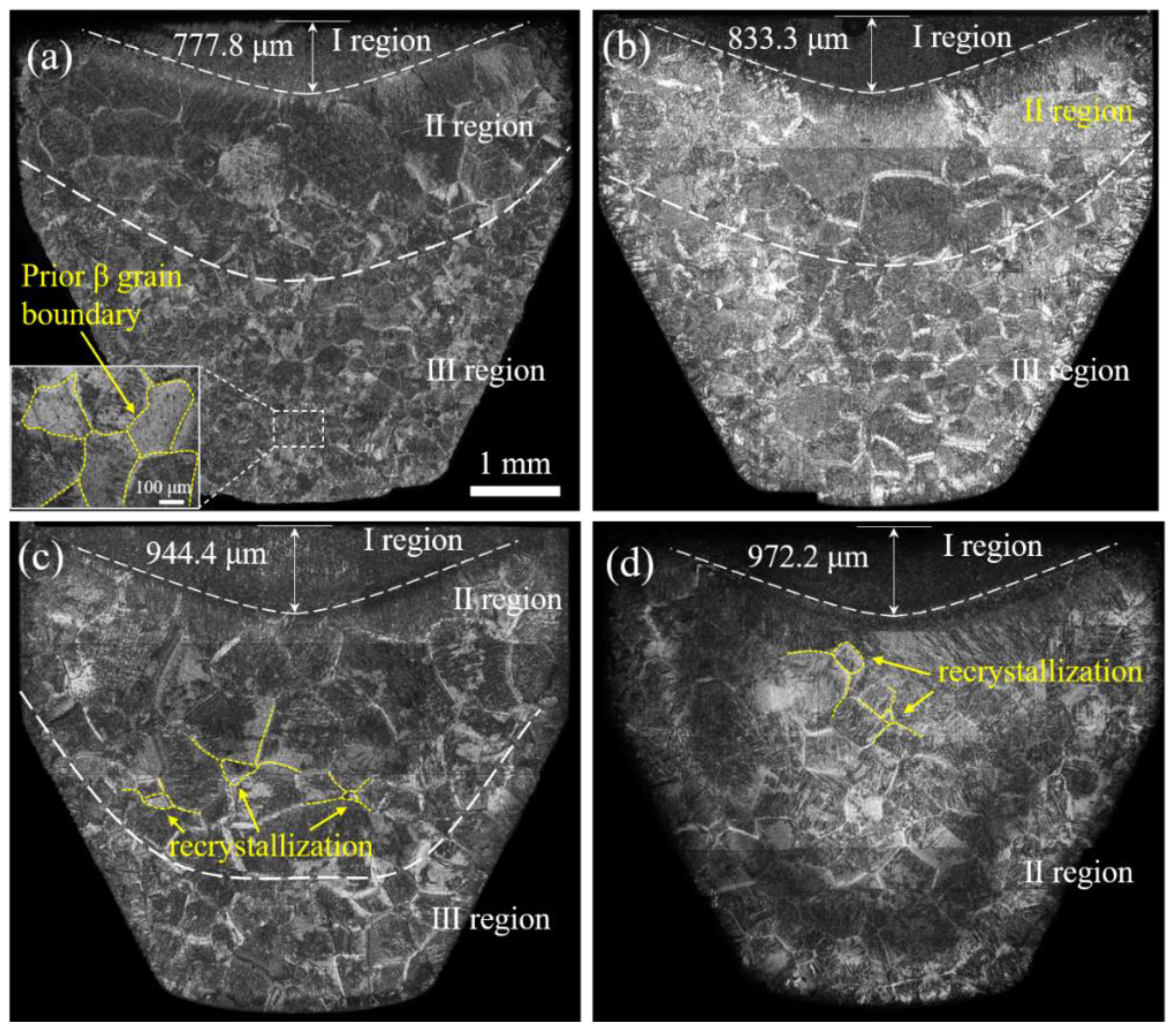
3.2. The Effect of Holding Time on the Microstructure Evolution of Billets
3.3. The Effect of TiC on the Extrusion Force
3.4. The Effect of β Grains on the Extrusion Force
4. Conclusions
- (1)
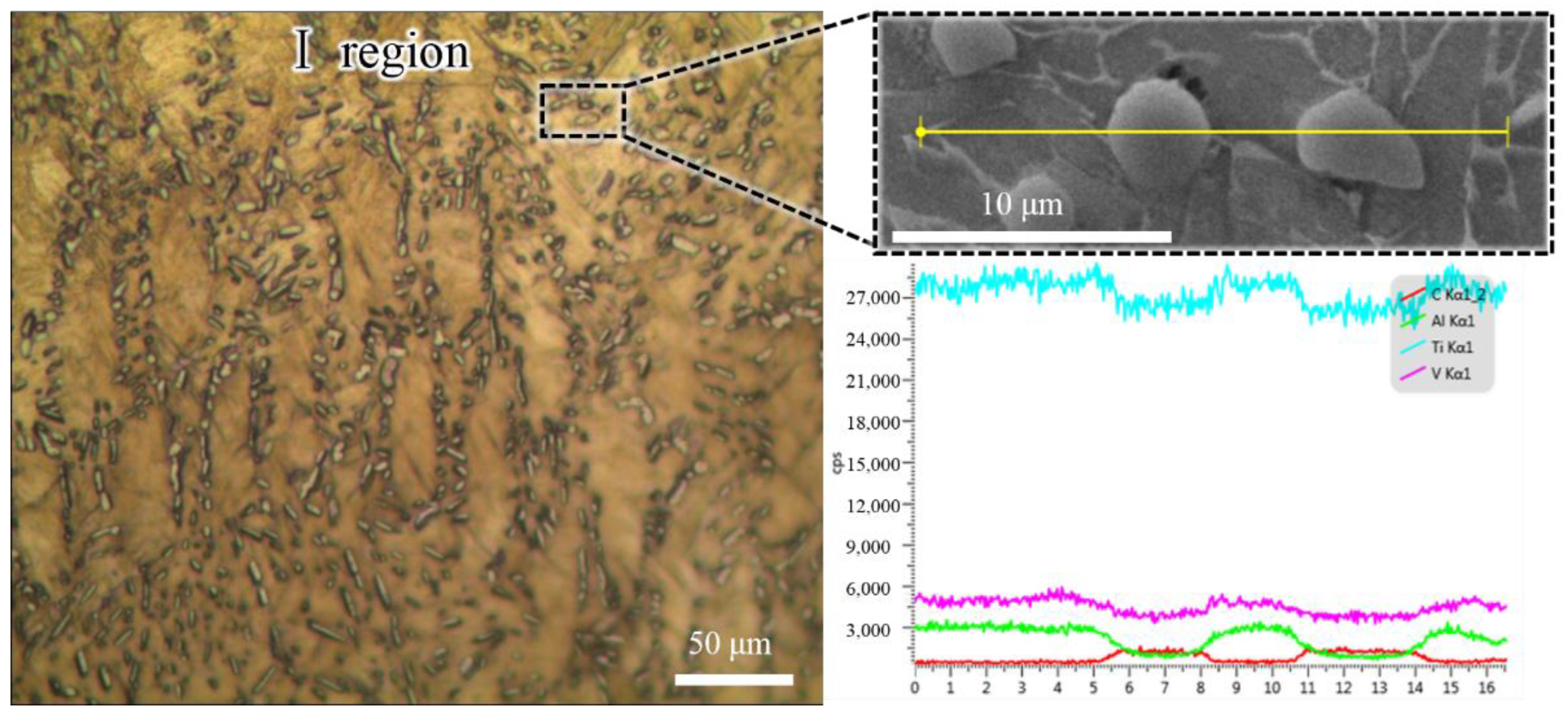
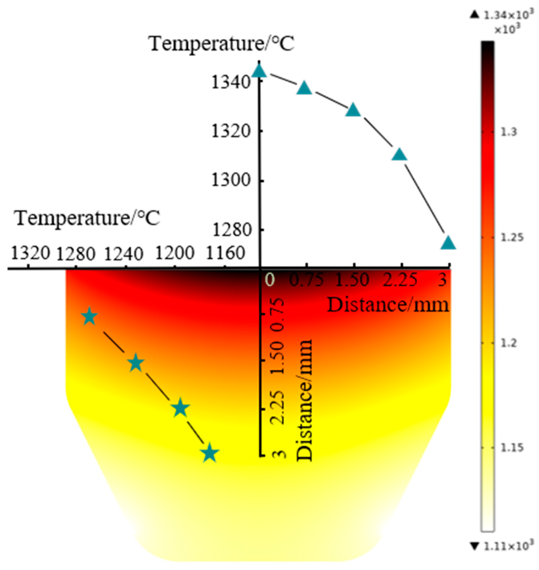
- A gradient temperature distribution from the upper surface center to the periphery inside the billet was observed because of the contact resistance and electric current density. The temperature gradient resulted in a carburized layer and a gradient distribution of β grains.
- (2)
- The carburized layer thickness and β grain size increased with the extension of the holding time. However, the β grain size was evenly distributed at a holding time of 180 s due to the rapid growth of recrystallized β grains.
- (3)
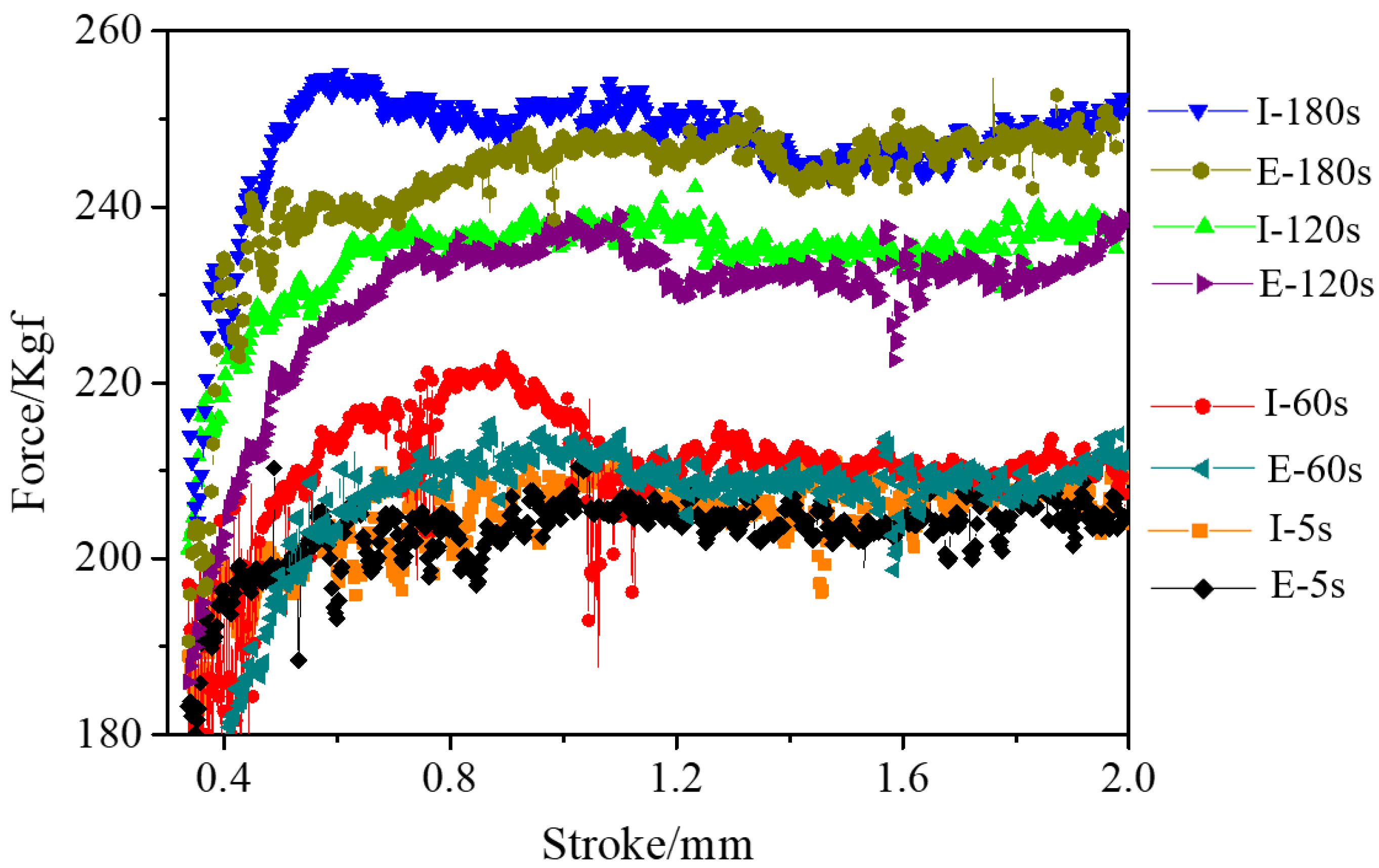
- The extrusion force increased with the holding time because of the carburized layer thickness and the prior β grain size, while the β grain size was the dominant factor in the extrusion force. Therefore, a shorter holding time at high temperatures is conducive to the plastic forming of Ti alloys.
- (4)
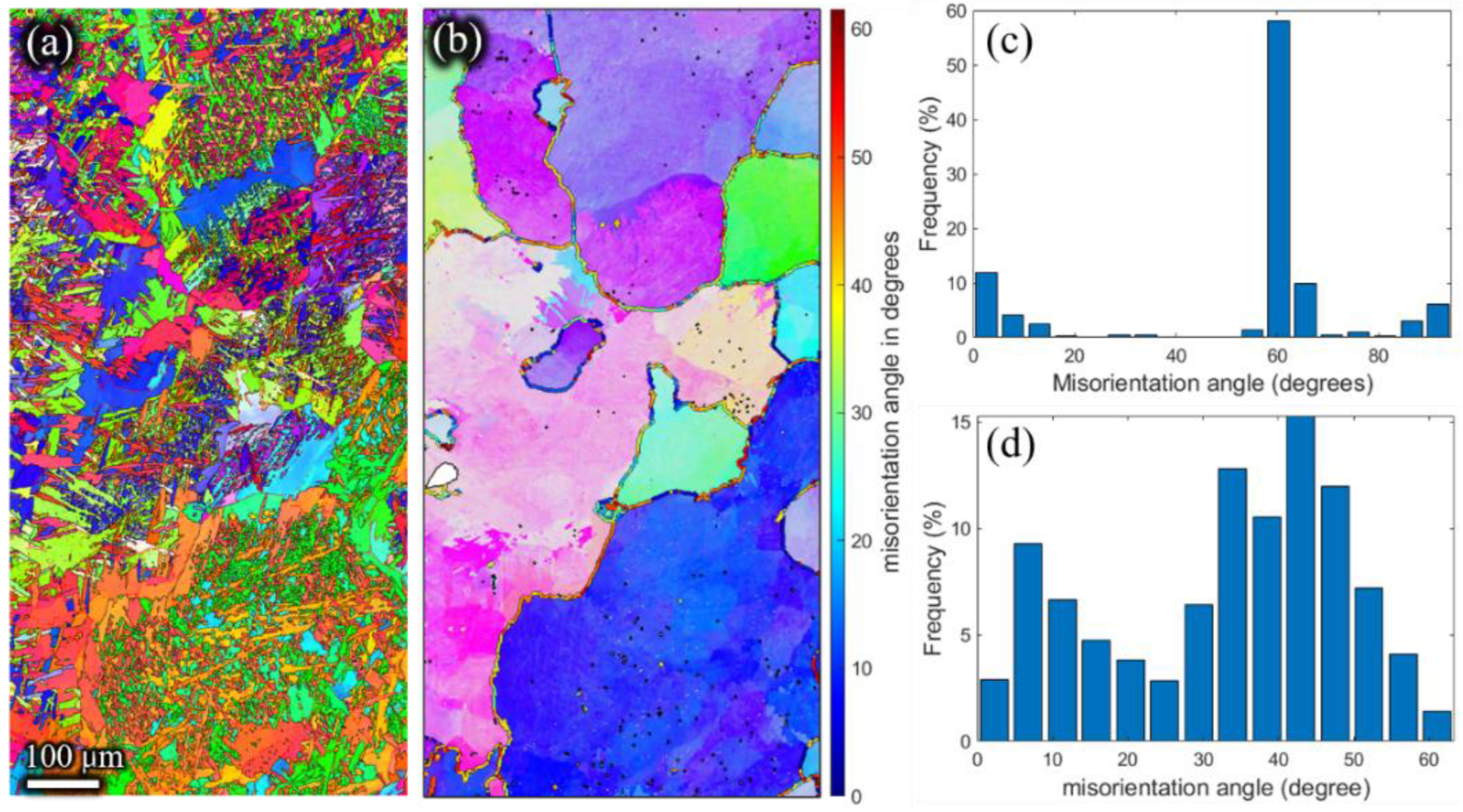
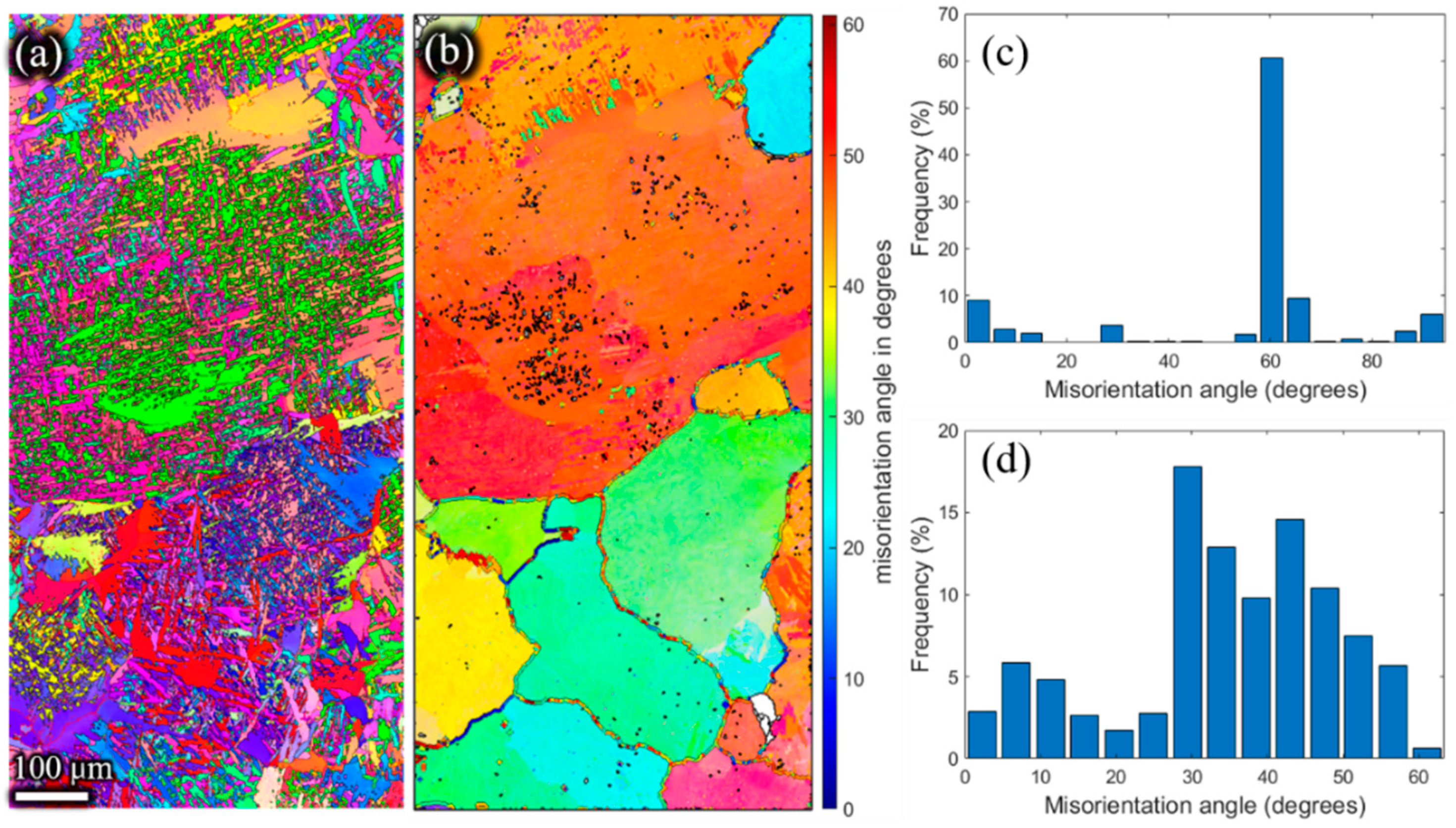
- The CDRX was the controlling mechanism during the plastic deformation of the micro-gears; the misorientation of the α variants followed the Burgers orientation relationship.
Author Contributions
Funding
Institutional Review Board Statement
Informed Consent Statement
Data Availability Statement
Conflicts of Interest
References
- Chaubey, S.K.; Jain, N.K. State-of-art review of past research on manufacturing of meso and micro cylindrical gears. Precis. Eng. 2018, 51, 702–728. [Google Scholar] [CrossRef]
- Saboori, A.; Abdi, A.; Fatemi, S.A.; Marchese, G.; Biamino, S.; Mirzadeh, H. Hot deformation behavior and flow stress modeling of Ti–6Al–4V alloy produced via electron beam melting additive manufacturing technology in single β-phase field. Mater. Sci. Eng. A 2020, 792, 139822. [Google Scholar] [CrossRef]
- Li, L.X.; Rao, K.P.; Lou, Y.; Peng, D.S. A study on hot extrusion of Ti-6Al-4V using simulations and experiments. Int. J. Mech. Sci. 2002, 44, 2415–2425. [Google Scholar] [CrossRef]
- Ye, X.X.; Imai, H.; Shen, J.H.; Chen, B.; Han, G.Q.; Umeda, J.; Takahashi, M.; Kondoh, K. Dynamic recrystallization behavior and strengthening-toughening effects in a near-α Ti-xSi alloy processed by hot extrusion. Mater. Sci. Eng. A 2017, 684, 165–177. [Google Scholar] [CrossRef]
- Yang, J.L.; Wang, G.F.; Zhang, W.C.; Chen, W.Z.; Jiao, X.Y.; Zhang, K.F. Microstructure evolution and mechanical properties of P/M Ti-22Al-25Nb alloy during hot extrusion. Mater. Sci. Eng. A 2017, 699, 210–216. [Google Scholar] [CrossRef]
- Zhou, W.; Yu, J.; Lu, X.; Lin, J.; Dean, T.A. International Journal of Machine Tools and Manufacture A comparative study on deformation mechanisms, microstructures and mechanical properties of wide thin-ribbed sections formed by sideways and forward extrusion. Int. J. Mach. Tools Manuf. 2021, 168, 103771. [Google Scholar] [CrossRef]
- Scott, B.; Overman, N.; Olszta, M.; Skszek, T.; Diciano, M.; Whalen, S. International Journal of Machine Tools and Manufacture Shear assisted processing and extrusion of enhanced strength aluminum alloy tubing. Int. J. Mach. Tools Manuf. 2021, 169, 103798. [Google Scholar] [CrossRef]
- Li, Y.; Chen, L.; Tang, J.; Zhao, G.; Zhang, C. Effects of asymmetric feeder on microstructure and mechanical properties of high strength Al-Zn-Mg alloy by hot extrusion. J. Alloys Compd. 2018, 749, 293–304. [Google Scholar] [CrossRef]
- Liu, X.Y.; Lu, L.W.; Sheng, K.; Zhou, T. Microstructure and Texture Evolution During the Direct Extrusion and Bending–Shear Deformation of AZ31 Magnesium Alloy. Acta Metall. Sin. Engl. Lett. 2019, 32, 710–718. [Google Scholar] [CrossRef] [Green Version]
- Akbar, A.; Sun, Y.; Cao, C.; Pruncu, C.; Wang, Y. Current failure mechanisms and treatment methods of hot forging tools (dies)—A review. Eng. Fail. Anal. 2021, 129, 105678. [Google Scholar] [CrossRef]
- Emamverdian, A.A.; Sun, Y.; Chunping, C. Deformation and wear in a H21 (3Cr2W8V) steel die during hot forging: Simulation, mechanical properties, and microstructural evolution. J. Mater. Res. Technol. 2021, 15, 268–277. [Google Scholar] [CrossRef]
- Yan, X.; Dan, L.; Yang, Y.; Tian, Y.; Huang, K. Effect of Heating Rate on Formability of Ti6Al4V Alloy Micro-gear Under an Electric Field. Rare Met. Mater. Eng. 2020, 49, 3294–3300. [Google Scholar]
- Bazhenov, V.E.; Tselovalnik, Y.V.; Koltygin, A.V.; Belov, V.D. Investigation of the Interfacial Heat Transfer Coefficient at the Metal–Mold Interface During Casting of an A356 Aluminum Alloy and AZ81 Magnesium Alloy into Steel and Graphite Molds. Int. J. Met. 2021, 15, 625–637. [Google Scholar] [CrossRef]
- Yang, X.; Huang, W.; Zhu, X.; Zhang, R.; Guo, F.; Hu, L. Characterization of the Hot Deformation Behaviour of an As-Extruded Al–Cu–Li Alloy by Constitutive Analysis. Met. Mater. Int. 2021, 27, 4793–4801. [Google Scholar] [CrossRef]
- Zheng, J.; Ran, J.Q.; Fu, M.W. Constitutive modeling of multiscale polycrystals considering grain structures and orientations. Int. J. Mech. Sci. 2022, 216, 106992. [Google Scholar] [CrossRef]
- Fu, M.W.; Chan, W.L. Micro-scaled progressive forming of bulk micropart via directly using sheet metals. Mater. Des. 2013, 49, 774–783. [Google Scholar] [CrossRef]
- Zhang, R.; Xu, Z.; Peng, L.; Lai, X.; Fu, M.W. Modelling of ultra-thin steel sheet in two-stage tensile deformation considering strain path change and grain size effect and application in multi-stage microforming. Int. J. Mach. Tools Manuf. 2021, 164, 103713. [Google Scholar] [CrossRef]
- Zheng, J.Y.; Yang, H.P.; Fu, M.W.; Ng, C. Study on size effect affected progressive microforming of conical flanged parts directly using sheet metals. J. Mater. Processing Technol. 2019, 272, 72–86. [Google Scholar] [CrossRef]
- Zhang, X.; Jiang, X.N.; Sun, C. Micro-stereolithography of polymeric and ceramic microstructures. Sens. Actuators A Phys. 1999, 77, 149–156. [Google Scholar] [CrossRef]
- Nishiyabu, K. Micro Metal Powder Injection Molding. Some Crit. Issues Inject. Molding 2012, 5, 105–130. [Google Scholar] [CrossRef] [Green Version]
- Ilie, C.; Popa, M.; Prioteasa, P.; Chiriţǎ, I.; Tǎnase, N. Applications of liga technology for the development of micromechanical systems. UPB Sci. Bull. Ser. D Mech. Eng. 2011, 73, 137–150. [Google Scholar]
- Tang, Y.; Tan, W.K.; Fuh, J.Y.H.; Loh, H.T.; Wong, Y.S.; Thian, S.C.H.; Lu, L. Micro-mould fabrication for a micro-gear via vacuum casting. J. Mater. Process. Technol. 2007, 192–193, 334–339. [Google Scholar] [CrossRef]
- Suzuki, Y.; Shiratori, T.; Murakawa, M.; Yang, M. Precision stamping process of metal micro gears. Procedia Manuf. 2018, 15, 1445–1451. [Google Scholar] [CrossRef]
- Dong, X.; Chen, F.; Chen, S.; Liu, Y.; Huang, Z.; Chen, H.; Feng, S.; Zhao, L.; Wu, Z.; Zhang, X. Microstructure and microhardness of hot extruded 7075 aluminum alloy micro-gear. J. Mater. Process. Technol. 2015, 219, 199–208. [Google Scholar] [CrossRef]
- Debin, S.; Jie, X.; Chunju, W.; Bin, G. Hybrid forging processes of micro-double gear using micro-forming technology. Int. J. Adv. Manuf. Technol. 2009, 44, 238–243. [Google Scholar] [CrossRef]
- Ali, M.Y.; Mustafizul Karim, A.N.; Adesta, E.Y.T.; Ismail, A.F.; Abdullah, A.A.; Idris, M.N. Comparative study of conventional and micro WEDM based on machining of meso/micro sized spur gear. Int. J. Precis. Eng. Manuf. 2010, 11, 779–784. [Google Scholar] [CrossRef]
- Zhang, Z.X.; Qu, S.J.; Feng, A.H.; Hu, X.; Shen, J. Microstructural mechanisms during multidirectional isothermal forging of as-cast Ti-6Al-4V alloy with an initial lamellar microstructure. J. Alloys Compd. 2019, 773, 277–287. [Google Scholar] [CrossRef]
- Preedawiphat, P.; Mahayotsanun, N.; Sucharitpwatskul, S. Finite element analysis of grain size effects on curvature in micro-extrusion. Appl. Sci. 2020, 10, 4767. [Google Scholar] [CrossRef]
- Wang, B.; Huang, L.J.; Hu, H.T.; Liu, B.X.; Geng, L. Superior tensile strength and microstructure evolution of TiB whisker reinforced Ti60 composites with network architecture after β extrusion. Mater. Charact. 2015, 103, 140–149. [Google Scholar] [CrossRef]
- Jiang, S.; Huang, L.; Gao, X.; Liu, G.; Zhang, R.; Jiao, Y.; Peng, S.; An, Q.; Wang, S.; Geng, L. Interstitial carbon induced FCC-Ti exhibiting ultrahigh strength in a Ti37Nb28Mo28-C7 complex concentrated alloy. Acta Mater. 2021, 203, 116456. [Google Scholar] [CrossRef]
- Mironov, S.; Sato, Y.S.; Kokawa, H.; Hirano, S.; Pilchak, A.L.; Semiatin, S.L. Microstructural Characterization of Friction-Stir Processed Ti-6Al-4V. Metals 2020, 10, 976. [Google Scholar] [CrossRef]
- Liu, Y.; Liu, Z.; Wang, M. Gradient microstructure evolution under thermo-mechanical coupling effects for a nickel-based powder metallurgy superalloy—Dynamic recrystallization coexist with static recrystallization. J. Mater. Process. Technol. 2021, 294, 117142. [Google Scholar] [CrossRef]
- Tang, X.F.; Shi, S.Q.; Fu, M.W. Interactive effect of grain size and crystal structure on deformation behavior in progressive micro-scaled deformation of metallic materials. Int. J. Mach. Tools Manuf. 2020, 148, 103473. [Google Scholar] [CrossRef]
- Gong, J.; Wilkinson, A.J. Sample size effects on grain boundary sliding. Scr. Mater. 2016, 114, 17–20. [Google Scholar] [CrossRef]
- Zou, Z.; Simonelli, M.; Katrib, J.; Dimitrakis, G.; Hague, R. Microstructure and tensile properties of additive manufactured Ti-6Al-4V with refined prior-β grain structure obtained by rapid heat treatment. Mater. Sci. Eng. A 2021, 814, 141271. [Google Scholar] [CrossRef]
- Jiang, M.G.; Xu, C.; Yan, H.; Fan, G.H.; Nakata, T.; Lao, C.S.; Chen, R.S.; Kamado, S.; Han, E.H.; Lu, B.H. Unveiling the formation of basal texture variations based on twinning and dynamic recrystallization in AZ31 magnesium alloy during extrusion. Acta Mater. 2018, 157, 53–71. [Google Scholar] [CrossRef]


| Reference | Material | Forming Method |
|---|---|---|
| [19] | Polymers | Micro-stereolithography |
| [20] | 17-4PH stainless steel | Powder injection molding |
| [21] | Nickel | LIGA (lithography, electroplating, molding) |
| [22] | Polyurethane resins and green waxes | Vacuum-casting |
| [23] | SUS304 | Stamping |
| [24] | 7075 Al alloy | Extrusion |
| [25] | Steel and aluminum alloys | Forging |
| [26] | Beryllium copper | Wire electrical discharge machining |
| Sample | Heating Rate (°C/s) | Holding Time (s) | Extrusion Rate (mm/s) |
|---|---|---|---|
| I-5s | 10 | 5 | 0.01 |
| I-60s | 10 | 60 | 0.01 |
| I-120s | 10 | 120 | 0.01 |
| I-180s | 10 | 180 | 0.01 |
Publisher’s Note: MDPI stays neutral with regard to jurisdictional claims in published maps and institutional affiliations. |
© 2022 by the authors. Licensee MDPI, Basel, Switzerland. This article is an open access article distributed under the terms and conditions of the Creative Commons Attribution (CC BY) license (https://creativecommons.org/licenses/by/4.0/).
Share and Cite
Yan, X.; Zhang, S.; Huang, K.; Yang, Y.; Wang, W.; Wu, M. Effect of Holding Time on the Extrusion Force and Microstructure Evolution during the Plastic Forming of Ti-6Al-4V Micro-Gears. Materials 2022, 15, 1507. https://doi.org/10.3390/ma15041507
Yan X, Zhang S, Huang K, Yang Y, Wang W, Wu M. Effect of Holding Time on the Extrusion Force and Microstructure Evolution during the Plastic Forming of Ti-6Al-4V Micro-Gears. Materials. 2022; 15(4):1507. https://doi.org/10.3390/ma15041507
Chicago/Turabian StyleYan, Xiangzhong, Shengwei Zhang, Kunlan Huang, Yi Yang, Wei Wang, and Mingxia Wu. 2022. "Effect of Holding Time on the Extrusion Force and Microstructure Evolution during the Plastic Forming of Ti-6Al-4V Micro-Gears" Materials 15, no. 4: 1507. https://doi.org/10.3390/ma15041507