
Cleavage Fracture of the Air Cooled Medium Carbon Microalloyed Forging Steels with Heterogeneous Microstructures

 , , and
Abstract
:1. Introduction
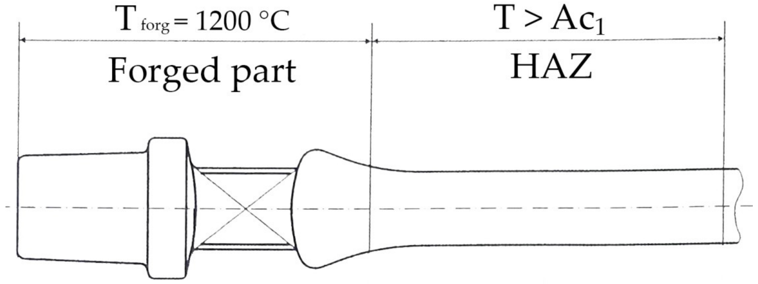
2. Materials and Methods
3. Results and Discussion
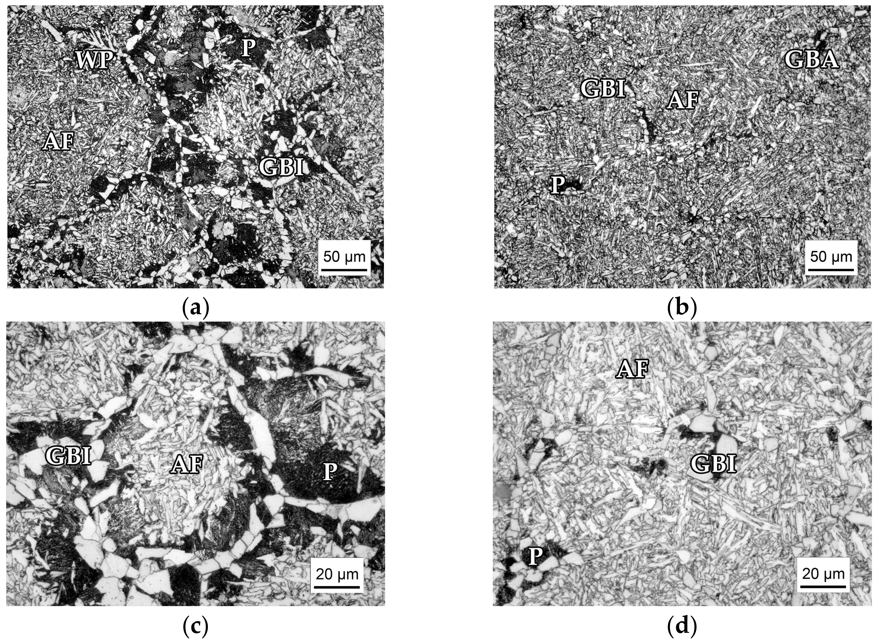
3.1. Microstructure
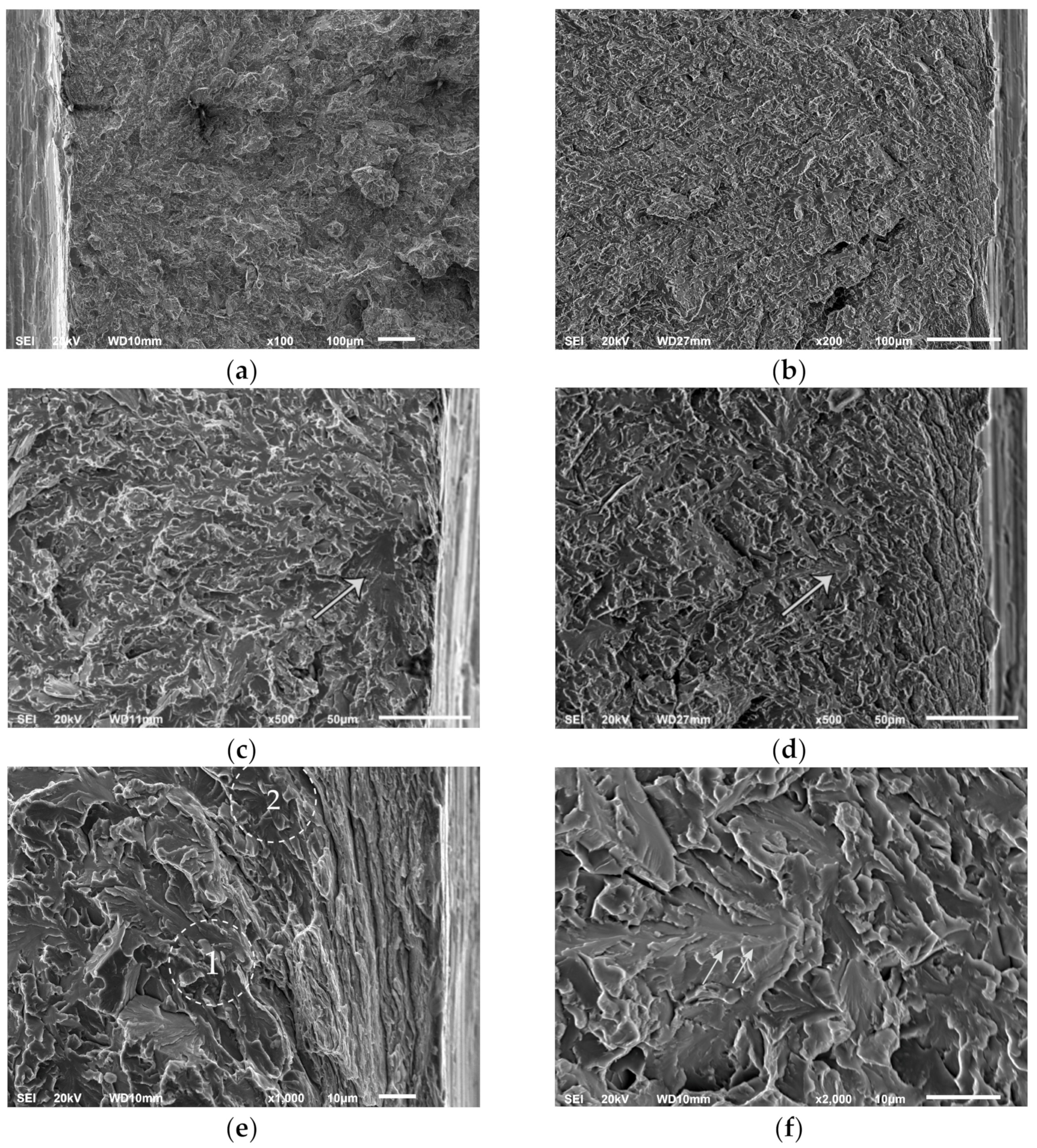
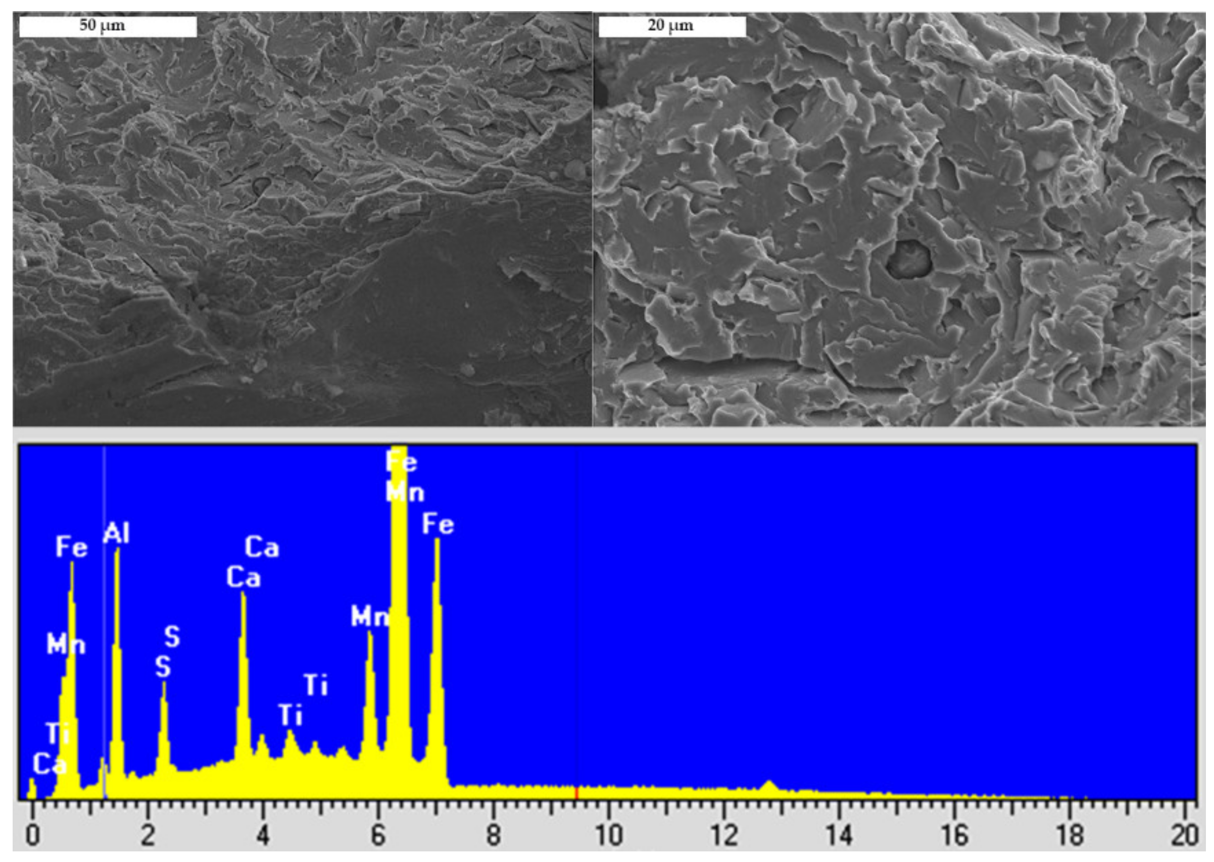
3.2. Fractography
4. Conclusions
- Cleavage fracture of air-cooled medium carbon microalloyed steels with predominantly acicular ferrite microstructure is initiated by the fracture of the coarse microstructural units, ferrite, and pearlite, under the plastic deformation at the notch root of the four-point bending specimen. In this case, fracture of the second phase particles is not involved in the cleavage fracture initiation process.
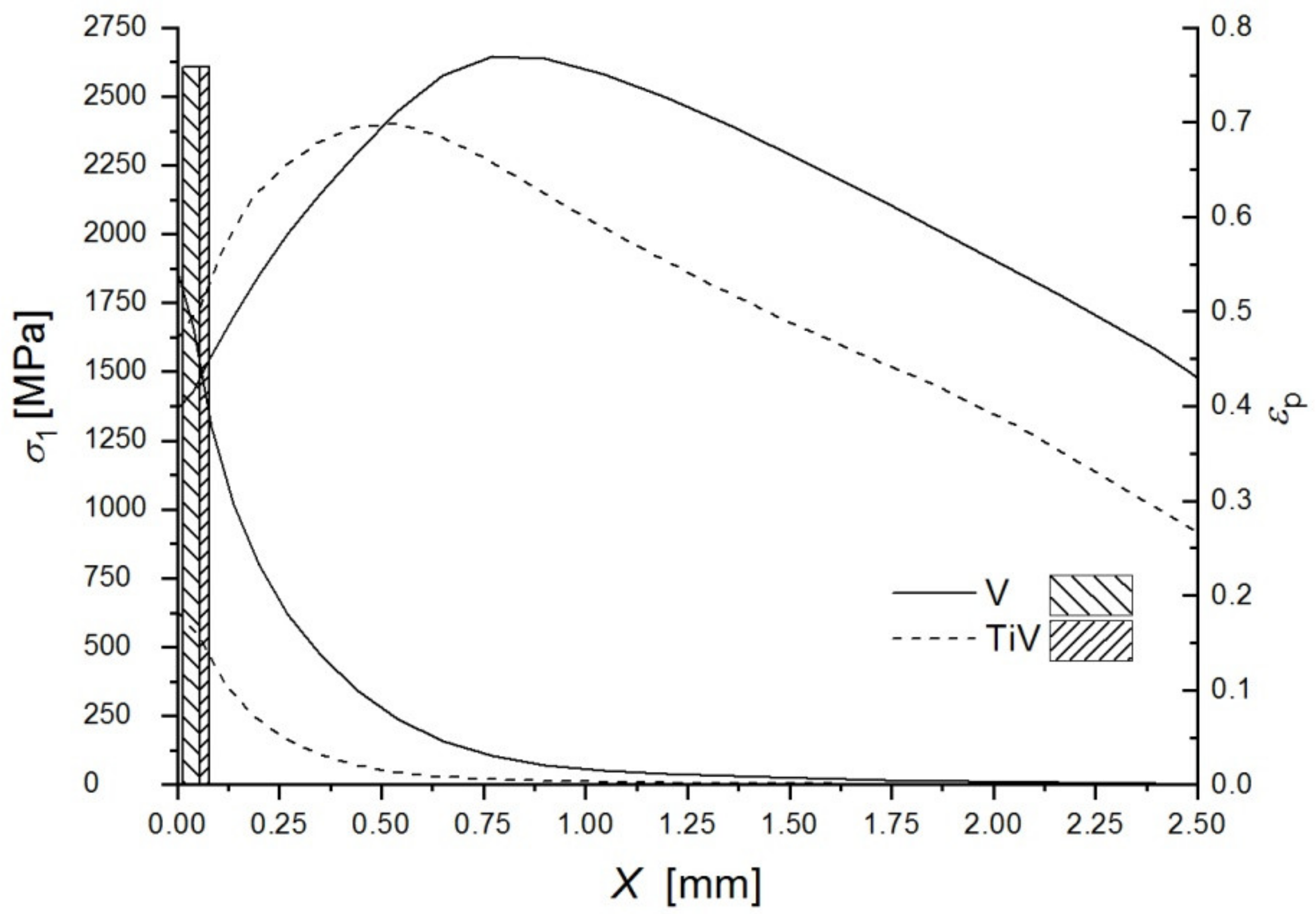
- Peak stress in front of the notch root of the four-point bending specimen is insufficient for the cleavage fracture initiation by fracture of coarse TiN particles in the microstructure consisting predominantly of acicular ferrite due to its fine-grained structure with a high density of high-angle boundaries and relatively low strength and considerable ductility at liquid nitrogen temperature, comparing to the ferritic-pearlitic structure.
- While the coarse ferrite grains and pearlite nodules govern the cleavage fracture initiation, stress and strain distribution in the four-point bending specimen are dominated by the acicular ferrite and its deformational characteristics. It is assumed that mechanical properties were also contributed by the retained austenite present in the acicular ferrite structure of the steel with higher carbon content and the Ti-V microalloying addition.
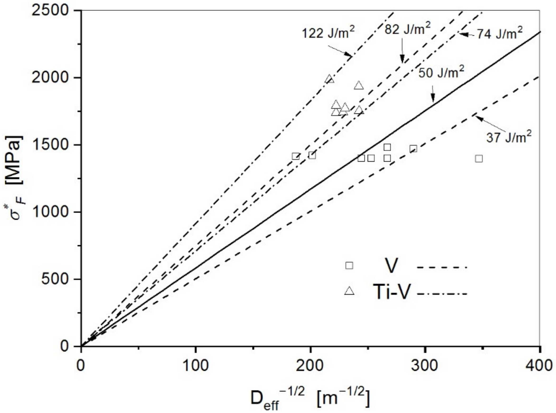
- Estimated values of the effective surface energy for the V steel with about 70% of the acicular ferrite of 37 Jm−2, and for the Ti-V steel with the acicular ferrite content as high as 96% of 74 Jm−2 are considered as the effective energy for the propagation of the crack through the grain boundaries, and therefore directly relate to the effect of the fine interlocking structure of acicular ferrite in the cleavage fracture mechanism.
Author Contributions
Funding
Data Availability Statement
Conflicts of Interest
References
- Engineer, S.; Huchtemann, B. Review and Development of Microalloyed Steels for Forgings, Bars and Wires. In Proceedings of the Second International Symposium on Microalloyed Bar & Forging Steel, Golden, CO, USA, 8–10 July 1996; pp. 61–78. [Google Scholar]
- Drobnjak, D.; Koprivica, A. Microalloyed bar and forging steels. In Proceedings of the Second International Symposium on Microalloyed Bar & Forging Steel, Golden, CO, USA, 8–10 July 1996; pp. 93–107. [Google Scholar]
- Glišić, D.; Radović, N.; Koprivica, A.; Fadel, A.; Drobnjak, D. Influence of reheating temperature and Vanadium content on transformation behavior and mechanical properties of medium carbon forging steels. ISIJ Int. 2010, 50, 601–606. [Google Scholar] [CrossRef] [Green Version]
- Ishikavaa, F.; Takahashi, T. The Formation ot Intragranular Steels for Hot-torging Plates in Medium-carbon and Its Effect on the Toughness. ISIJ Int. 1995, 35, 1128–1133. [Google Scholar] [CrossRef] [Green Version]
- Babu, S.S. The mechanism of acicular ferrite in weld deposits. Curr. Opin. Solid State Mater. Sci. 2004, 8, 267–278. [Google Scholar] [CrossRef]
- He, K.; Edmonds, D.V. Formation of acicular ferrite and influence of vanadium alloying. Mater. Sci. Technol. 2002, 18, 289–296. [Google Scholar] [CrossRef]
- Dong, J.; Liu, C.; Liu, Y.; Zhou, X.; Guo, Q.; Li, H. Isochronal phase transformation of Nb–V–Ti microalloyed ultra-high strength steel upon cooling. Fusion Eng. Des. 2017, 125, 423–430. [Google Scholar] [CrossRef]
- Xiong, Z.; Liu, S.; Wang, X.; Shang, C.; Li, X.; Misra, R.D.K. The contribution of intragranular acicular ferrite microstructural constituent on impact toughness and impeding crack initiation and propagation in the heat-affected zone (HAZ) of low-carbon steels. Mater. Sci. Eng. A 2015, 636, 117–123. [Google Scholar] [CrossRef]
- Peng, Y.; Chen, W.; Xu, Z. Study of high toughness ferrite wire for submerged arc welding of pipeline steel. Mater. Charact. 2001, 47, 67–73. [Google Scholar] [CrossRef]
- Linaza, M.A.; Romero, J.L.; Rodriguez-Ibabe, J.M.; Urcola, J.J. Improvement of fracture toughness of forging steels microalloyed with titanium by accelerated cooling after hot working. Scr. Metall. Et Mater. 1993, 29, 1217–1222. [Google Scholar] [CrossRef]
- Garcia-Mateo, C.; Capdevila, C.; Caballero, F.G.; de Andrés, C.G. Influence of V precipitates on acicular ferrite transformation part 1: The role of nitrogen. ISIJ Int. 2008, 48, 1270–1275. [Google Scholar] [CrossRef] [Green Version]
- Díaz-Fuentes, M.; Gutiérrez, I. Analysis of different acicular ferrite microstructures generated in a medium-carbon molybdenum steel. Mater. Sci. Eng. A 2003, 363, 316–324. [Google Scholar] [CrossRef]
- Díaz-Fuentes, M.; Iza-Mendia, A.; Gutiérrez, I. Analysis of different acicular ferrite microstructures in low-carbon steels by electron backscattered diffraction. Study of their toughness behavior. Metall. Mater. Trans. A 2003, 34, 2505–2516. [Google Scholar] [CrossRef]
- Rasouli, D.; Asl, S.K.; Akbarzadeh, A.; Daneshi, G.H. Effect of cooling rate on the microstructure and mechanical properties of microalloyed forging steel. J. Mater. Process. Technol. 2008, 206, 92–98. [Google Scholar] [CrossRef]
- Cao, Z.Q.; Bao, Y.P.; Xia, Z.H.; Luo, D.; Guo, A.M.; Wu, K.M. Toughening mechanisms of a high-strength acicular ferrite steel heavy plate. Int. J. Miner. Metall. Mater. 2010, 17, 567–572. [Google Scholar] [CrossRef]
- Balart, M.J.; Davis, C.L.; Strangwood, M. Observations of cleavage initiation at (Ti,V)(C,N) particles of heterogeneous composition in microalloyed steels. Scr. Mater. 2004, 50, 371–375. [Google Scholar] [CrossRef]
- Alexander, D.J.; Bernstein, I.M. Cleavage fracture in pearlitic eutectoid steel. Metall. Trans. A 1989, 20, 2321–2335. [Google Scholar] [CrossRef]
- Echeverría, A.; Rodriguez-Ibabe, J.M. The role of grain size in brittle particle induced fracture of steels. Mater. Sci. Eng. A 2003, 346, 149–158. [Google Scholar] [CrossRef]
- Curry, D.A.; Knott, J.F. Effects of microstructure on cleavage fracture stress in steel. Met. Sci. 1978, 12, 511–514. [Google Scholar] [CrossRef]
- Linaza, M.A.; Rodriguez-Ibabe, J.M.; Urcola, J.J. Determination of the energetic parameters controlling cleavage fracture initiation in steels. Fatigue Fract. Eng. Mater. Struct. 1997, 20, 619–632. [Google Scholar] [CrossRef]
- Balart, M.J.; Davis, C.L.; Strangwood, M.; Knott, J.F. Cleavage initiation in Ti-V-N and V-N microalloyed forging steels. Mater. Sci. Forum 2005, 500–501, 729–736. [Google Scholar] [CrossRef]
- Du, J.; Strangwood, M.; Davis, C.L. Effect of TiN Particles and Grain Size on the Charpy Impact Transition Temperature in Steels. J. Mater. Sci. Technol. 2012, 28, 878–888. [Google Scholar] [CrossRef]
- Rodriguez-Ibabe, J.M. The role of microstructure in toughness behaviour of microalloyed steels. Mater. Sci. Forum 1998, 284, 51–62. [Google Scholar] [CrossRef]
- Bhadeshia, H. Physical metallurgy of steels. Phys. Metall. 2014, 2014, 2157–2214. [Google Scholar] [CrossRef]
- Schindelin, J.; Arganda-Carreras, I.; Frise, E.; Kaynig, V.; Longair, M.; Pietzsch, T.; Preibisch, S.; Rueden, C.; Saalfeld, S.; Schmid, B.; et al. Fiji: An open-source platform for biological-image analysis. Nat. Methods 2012, 9, 676–682. [Google Scholar] [CrossRef] [PubMed] [Green Version]
- Griffiths, J.R.; Owen, D.R.J. An elastic-plastic stress analysis for a notched bar in plane strain bending. J. Mech. Phys. Solids 1971, 19, 419–431. [Google Scholar] [CrossRef]
- Bhadeshia, H.; Honeycombe, R. Chapter 13—Weld Microstructures. Steels Microstruct. Prop. 2017, 2017, 377–400. [Google Scholar] [CrossRef]
- Shim, J.-H.; Oh, Y.-J.; Suh, J.-Y.; Cho, Y.W.; Shim, J.-D.; Byun, J.-S.; Lee, D.N. Ferrite nucleation potency of non-metallic inclusions in medium carbon steels. Acta Mater. 2001, 49, 2115–2122. [Google Scholar] [CrossRef]
- Adrian, H. Microalloying ’95. In Proceedings of the International Conference “Microalloying ‘95”, ISS, Pittsburgh, PA, USA, 11–14 June 1995; p. 285. [Google Scholar]
- Capdevila, C.; Caballero, F.G.; García-Mateo, C.; de Andrés, C.G. The role of inclusions and austenite grain size on intragranular nucleation of ferrite in medium carbon microalloyed steels. Mater. Trans. 2004, 45, 2678–2685. [Google Scholar] [CrossRef] [Green Version]
- Sage, A.M. An overview of the use of microalloys in HSLA steels with particular reference to vanadium and titanium. HSLA Steels Process. Prop. Appl. 1990, 51–60. [Google Scholar] [CrossRef]
- Radović, N.; Koprivica, A.; Glišić, D.; Fadel, A.; Drobnjak, D. Influence of Cr, Mn and Mo on structure and properties of V microalloyed medium carbon forging steels. MJoM 2010, 16, 1053–1058. [Google Scholar]
- Madariaga, I.; Gutiérrez, I. Nucleation of acicular ferrite enhanced by the precipitation of CuS on MnS particles. Scr. Mater. 1997, 37, 1185–1192. [Google Scholar] [CrossRef]
- Sarma, D.S.; Karasev, A.V.; Jönsson, P.G. On the role of non-metallic inclusions in the nucleation of acicular ferrite in steels. ISIJ Int. 2009, 49, 1063–1074. [Google Scholar] [CrossRef] [Green Version]
- Madariaga, I.; Romero, J.L.; Gutiérrez, I. Upper acicular ferrite formation in a medium-carbon microalloyed steel by isothermal transformation: Nucleation enhancement by CuS. Metall. Mater. Trans. A 1998, 29, 1003–1015. [Google Scholar] [CrossRef]
- Jin, H.-H.; Shim, J.-H.; Cho, Y.W.; Lee, H.-C. Formation of Intragranular Acicular Ferrite Grains in a Ti-containing Low Carbon Steel. ISIJ Int. 2003, 43, 1111–1113. [Google Scholar] [CrossRef]
- Zhang, S.; Hattori, N.; Enomoto, M.; Tarui, T. Ferrite Nucleation at Ceramic/Austenite Interfaces. ISIJ Int. 1996, 36, 1301–1309. [Google Scholar] [CrossRef]
- Madariaga, I.; Gutierrez, I.; Bhadeshia, H. Acicular ferrite morphologies in a medium-carbon microalloyed steel. Metall. Mater. Trans. A 2001, 32, 2187–2197. [Google Scholar] [CrossRef]
- Fadel, A.; Glišić, D.; Radović, N.; Drobnjak, D. Intragranular ferrite morphologies in medium carbon vanadium-microalloyed steel. J. Min. Metall. Sect. B Metall. 2013, 49, 237–244. [Google Scholar] [CrossRef]
- Martin, J.I.S.; Rodriguez-Ibabe, J.M. Determination of energetic parameters controlling cleavage fracture in a Ti-V microalloyed ferrite-pearlite steel. Scr. Mater. 1999, 40, 459–464. [Google Scholar] [CrossRef]
- Linaza, M.A.; Romero, J.L.; Rodriguez-Ibabe, J.M.; Urcola, J.J. Influence of the microstructure on the fracture toughness and fracture mechanisms of forging steels microalloyed with titanium with ferrite-pearlite structures. Scr. Metall. Mater. States 1993, 29. [Google Scholar] [CrossRef]
- Gourgue, A.-F.; Flower, H.M.; Lindley, T.C. Electron backscattering diffraction study of acicular ferrite, bainite, and martensite steel microstructures. Mater. Sci. Technol. 2000, 16, 26–40. [Google Scholar] [CrossRef]
- Linaza, M.A.; Romero, J.L.; Rodríguez-Ibabe, J.M.; Urcola, J.J. Cleavage fracture of microalloyed forging steels. Scr. Metall. Mater. 1995, 32, 395–400. [Google Scholar] [CrossRef]
- Linaza, M.A.; Romero, J.L.; Rodriguez-Ibabe, J.M.; Urcola, J.J. Influence of the microstructure on the ductile-brittle behavior of engineering steels containing brittle particles. In Proceedings of the 36th Mechanical Working and Steel Processing Conference, Baltimore, MD, USA, 17–18 October 1994; pp. 483–494. [Google Scholar]
- Smith, E. Cleavage fracture in mild steel. Int. J. Fract. Mech. 1968, 4, 131–145. [Google Scholar] [CrossRef]
- Lindley, T.C.; Oates, G.; Richards, C.E. A critical of carbide cracking mechanisms in ferride/carbide aggregates. Acta Metall. 1970, 18, 1127–1136. [Google Scholar] [CrossRef]
- Ghosh, A.; Ray, A.; Chakrabarti, D.; Davis, C.L. Cleavage initiation in steel: Competition between large grains and large particles. Mater. Sci. Eng. A 2013, 561, 126–135. [Google Scholar] [CrossRef]
- Lewandowski, J.J.; Thompson, A.W. Micromechanisms of cleavage fracture in fully pearlitic microstructures. Acta Metall. 1987, 35, 1453–1462. [Google Scholar] [CrossRef]
- Strnadel, B.; Haušild, P. Statistical scatter in the fracture toughness and Charpy impact energy of pearlitic steel. Mater. Sci. Eng. A 2008, 486, 208–214. [Google Scholar] [CrossRef]
- Glišić, D.; Fadel, A.; Radović, N.; Drobnjak, D.; Zrilić, M. Deformation behaviour of two continuously cooled vanadium microalloyed steels at liquid nitrogen temperature. Hem. Ind. 2013, 67, 981–988. [Google Scholar] [CrossRef] [Green Version]
- Burns, K.W.; Pickering, F.B. Deformation+ fracture of Ferrite-pearlite Structures. J. Iron Steel Inst. 1964, 202, 899. [Google Scholar]
- Irvine, K.J. Development of High-Strength Steels. J. Iron Steel Inst. 1962, 200, 820. [Google Scholar]
- Matlock, D.K.; Krauss, G.; Speer, J.G. Microstructures and properties of direct-cooled microalloy forging steels. J. Mater. Process. Technol. 2001, 117, 324–328. [Google Scholar] [CrossRef]
- Caballero, F.G.; Garcia-Mateo, C. Phase transformations in advanced bainitic steels. In Woodhead Publishing Series in Metals and Surface Engineering; Pereloma, E., Edmonds, D.V., Eds.; Woodhead Publishing: Sawston, UK, 2012; Volume 2, pp. 271–294. [Google Scholar] [CrossRef]
- Bhadeshia, H.K.D.H. Bainite in Steels: Theory and Practice, 3rd ed.; Maney Publishing: Leeds, UK, 2015. [Google Scholar]
- Diaz, M.; Madariaga, I.; Rodriguez-Ibabe, J.M.; Gutierrez, I. Improvement of mechanical properties in structural steels by development of acicular ferrite microstructures. J. Constr. Steel Res. 1998, 46, 413–414. [Google Scholar] [CrossRef]
- Echeverria, A.; Rodriguez-Ibabe, J.M. Cleavage micromechanisms on microalloyed steels. Evolution with temperature of some critical parameters. Scr. Mater. 2004, 50, 307–312. [Google Scholar] [CrossRef]

| Steel | C | Si | Mn | P | S | Cr | Ni | Mo | V | Ti | Al | Nb | N |
|---|---|---|---|---|---|---|---|---|---|---|---|---|---|
| Ti-V | 0.309 | 0.485 | 1.531 | 0.0077 | 0.0101 | 0.265 | 0.200 | 0.041 | 0.123 | 0.011 | 0.017 | 0.003 | 0.0228 |
| V | 0.256 | 0.416 | 1.451 | 0.0113 | 0.0112 | 0.201 | 0.149 | 0.023 | 0.099 | 0.002 | 0.038 | 0.002 | 0.0229 |
| Steel | [Ti] [ppm] | [N] [ppm] | [N]TiN [ppm] | [N]VN [ppm] | [V] [wt.%] | [V]VN [wt.%] | [V]excess [wt.%] | TVN [°C] | TVC [°C] |
|---|---|---|---|---|---|---|---|---|---|
| Ti-V | 110 | 228 | 32 | 196 | 0.123 | 0.071 | 0.052 | 1117 | 894 |
| V | 20 | 229 | 6 | 223 | 0.099 | 0.081 | 0.018 | 1108 | 869 |
| V Steel Sample | σF [MPa] | σF/σ0 | σ1max [MPa] | X0 [μm] | σF* [MPa] | εpc | Dmax × Dmin [μm] | Deff [μm] | γ [Jm−2] |
|---|---|---|---|---|---|---|---|---|---|
| 1 | 1193 | 1.54 | 2645 | 32 | 1419 | 0.493 | 36.8 × 15.5 | 24.5 | 72.3 |
| 53 | 1471 | 0.450 | 12.8 × 17.3 | 11.9 | 37.7 | ||||
| 2 | 1268 | 1.64 | 2671 | 19 | 1400 | 0.634 | 23.7 × 9.8 | 15.6 | 44.7 |
| 19 | 1400 | 0.634 | 21.0 × 11.3 | 16.7 | 48.0 | ||||
| 28 | 1414 | 0.616 | 29.3 × 24.1 | 28.5 | 83.7 | ||||
| 3 | 1049 | 1.35 | 2595 | 15 | 1398 | 0.369 | 41.0 × 8.1 | 14.0 | 40.1 |
| 14 | 1396 | 0.370 | 8.6 × 6.8 | 8.3 | 23.6 | ||||
| 4 | 1152 | 1.49 | 2640 | 56 | 1479 | 0.409 | 34.7 × 8.2 | 14.0 | 45.1 |
| Ti-V Steel Sample | σF [MPa] | σF/σ0 | σ1max [MPa] | X0 [μm] | σF* [MPa] | εpc | Dmax × Dmin [μm] | Deff [μm] | γ [Jm−2] |
| 1 | 759 | 0.85 | 2139 | 78 | 1739 | 0.060 | 20.4 × 18.3 | 20.2 | 89.7 |
| 2 | 934 | 1.04 | 2402 | 59 | 1751 | 0.152 | 18.8 × 12.7 | 17.0 | 76.5 |
| 56 | 1740 | 0.154 | 22.3 × 13.6 | 19.1 | 85.0 | ||||
| 3 | 904 | 1.01 | 2343 | 112 | 1934 | 0.092 | 17.2 × 15.3 | 17.0 | 93.4 |
| 131 | 1983 | 0.082 | 22.1 × 17.6 | 21.3 | 123.0 | ||||
| 4 | 950 | 1.06 | 2430 | 71 | 1792 | 0.156 | 35.4 × 12.3 | 20.2 | 95.2 |
| 65 | 1770 | 0.161 | 29.1 × 11.8 | 18.8 | 86.6 |
Publisher’s Note: MDPI stays neutral with regard to jurisdictional claims in published maps and institutional affiliations. |
© 2022 by the authors. Licensee MDPI, Basel, Switzerland. This article is an open access article distributed under the terms and conditions of the Creative Commons Attribution (CC BY) license (https://creativecommons.org/licenses/by/4.0/).
Share and Cite
Jovanović, G.; Glišić, D.; Dikić, S.; Radović, N.; Patarić, A. Cleavage Fracture of the Air Cooled Medium Carbon Microalloyed Forging Steels with Heterogeneous Microstructures. Materials 2022, 15, 1760. https://doi.org/10.3390/ma15051760
Jovanović G, Glišić D, Dikić S, Radović N, Patarić A. Cleavage Fracture of the Air Cooled Medium Carbon Microalloyed Forging Steels with Heterogeneous Microstructures. Materials. 2022; 15(5):1760. https://doi.org/10.3390/ma15051760
Chicago/Turabian StyleJovanović, Gvozden, Dragomir Glišić, Stefan Dikić, Nenad Radović, and Aleksandra Patarić. 2022. "Cleavage Fracture of the Air Cooled Medium Carbon Microalloyed Forging Steels with Heterogeneous Microstructures" Materials 15, no. 5: 1760. https://doi.org/10.3390/ma15051760